the12volt.com spacer
icon

drl relay


Post ReplyPost New Topic
< Prev Topic Next Topic >
b3tn01hasd1s 
Member - Posts: 2
Member spacespace
Joined: November 15, 2011
Location: Indiana, United States
Posted: September 19, 2012 at 3:41 PM / IP Logged  
So i need some help designing a circuit for my DRL's. The following are the constraints,
*On with blinkers
*on with Low Beams
*On for 30 seconds when unlock button from remote is hit
Thanks in Advance
b3tn01hasd1s 
Member - Posts: 2
Member spacespace
Joined: November 15, 2011
Location: Indiana, United States
Posted: September 19, 2012 at 3:42 PM / IP Logged  
BTW it is a 2006 honda accord lx. I am installing separate LED Strips
howie ll 
Pot Metal - Posts: 16,466
Pot Metal spacespace
Joined: January 09, 2007
Location: United Kingdom
Posted: September 20, 2012 at 2:33 PM / IP Logged  
A lot easier to simply wire them into your parking light or low beam circuit, on with blinkers might give you legal problems.
As for staying on why?
Use a DEI 528t timer either with your lock wire or an alarm's GWA wire.
rfsduarte 
Member - Posts: 1
Member spacespace
Joined: November 29, 2012
Posted: January 16, 2013 at 2:07 AM / IP Logged  

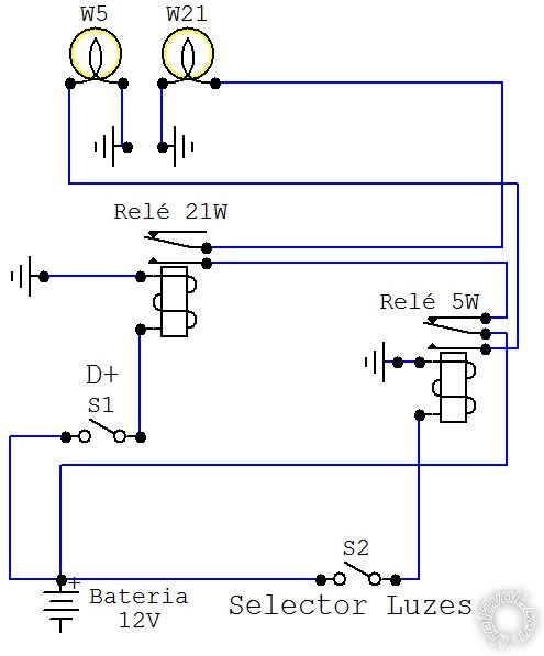
drl relay -- posted image.

turboled 
Member - Posts: 22
Member spacespace
Joined: December 29, 2006
Posted: January 16, 2013 at 7:17 AM / IP Logged  
You can use a TPC module to let the LED flash with blinkers and steady with parking lights. If you have dual-color LEDs (amber + white) it's even better.
http://www.exledusa.com/exled-2color-2way-turn-position-lamp-control-module-tpc-v.2.html
oldspark 
Gold - Posts: 4,913
Gold spacespace
Joined: November 03, 2008
Location: Australia
Posted: January 16, 2013 at 8:05 AM / IP Logged  
Although this was a sleeping 4-month old thread and I'm a bit puzzled by the circuit shown, that TPC is a good find.
It shows the hold-off behavior that I keep mentioning for these types of circuits - ie, the WHITE/ parkers stay off when a flashing signal is provided and hold off for about one second after the last flash.
That's required for any such flasher combined with clearance, stop, or reverse lights.
That TPC could probably drive a relay for normal bulbs (ie, 2 relays) or even have its output OR'd (2 diodes) for single-color LEDs or into a relay for combined stop/flasher bulbs etc.
Two TPCs are required - one per side. (Hence 4 relays, or 2 relays plus 4 diodes for the "single bulb" situation in which case I'd probably prefer my 2x DPDT relay solution with the repositioned flasher can.)
   
And it's 4 TPCs if using the scheme for each end - ie, rear is brakes or tails or reverse with flashers; front is parkers or DRLs with flashers.   
oldspark 
Gold - Posts: 4,913
Gold spacespace
Joined: November 03, 2008
Location: Australia
Posted: January 17, 2013 at 6:33 PM / IP Logged  
PS - I also noted exLED's TPC v.3 for R-LED as opposed to turboled's TPC v.2 - 2Color (2Way) Turn & parker.
I thought that by description the v.3 does what I described for v.2 with diodes and a single LED/bulb, but the info given is vague and they seem to show the same (youtube) video of its operation.
turboled 
Member - Posts: 22
Member spacespace
Joined: December 29, 2006
Posted: January 17, 2013 at 7:47 PM / IP Logged  
I believe I was mistaken too... v2 seems to work with 2 independent LED bulbs (2 positives, common ground) while the v3 works by reversing the polarity.
oldspark 
Gold - Posts: 4,913
Gold spacespace
Joined: November 03, 2008
Location: Australia
Posted: January 17, 2013 at 8:19 PM / IP Logged  
Your interpretation is certainly better than mine!
I assume one thing from the title, but something different when looking at the number of wires etc.
But I am certainly grateful that you linked that product. Thanks!   
I was thinking of contacting them not only for a "well done" etc, but also to ask for output current capability as well as an operational clarification.
Mind you, with an 8-pin PICAXE 08 it isn't too hard to program. They are less than $5 each (08M2, viz the PIC12F1840) and a single 08M2 should do both sides with ease, and 4 corners etc with a bit of trickery (ie, combining inputs thru a resistive voltage ladder etc) else a bigger PIC could be used.   
Those PICs merely require a 5V regulator (small 3-pin type) maybe with some added +12V vehicle spike protection, power filter cap(s), and suitable output drivers for lams, LEDs or relays (eg. MOSFETs or transistors).
Plus the essential 2 on-board programming resistors and a serial programming interface (PC serial else via USB-serial converter) and the programming using the free tools available.
There's a bit of a learning curve but there are heaps of open-source examples and public links.
And once done, almost anything is possible, and analogaly complex things become quite easy and cheap (eg, switching and dimming of LEDs for timed circuits like puddle lights or stop/flashers or flashing stop lights and combined stop & tail LEDs/bulbs etc).

Sorry, you can NOT post a reply.
This topic is closed.

  Printable version Printable version Post ReplyPost New Topic
You cannot post new topics in this forum
You cannot reply to topics in this forum
You cannot delete your posts in this forum
You cannot edit your posts in this forum
You cannot create polls in this forum
You cannot vote in polls in this forum

  •  
Search the12volt.com
Follow the12volt.com Follow the12volt.com on Facebook
Wednesday, April 24, 2024 • Copyright © 1999-2024 the12volt.com, All Rights Reserved Privacy Policy & Use of Cookies
Disclaimer: *All information on this site ( the12volt.com ) is provided "as is" without any warranty of any kind, either expressed or implied, including but not limited to fitness for a particular use. Any user assumes the entire risk as to the accuracy and use of this information. Please verify all wire colors and diagrams before applying any information.

Secured by Sectigo
the12volt.com spacer
Support the12volt.com
Top
the12volt.com spacer