the12volt.com spacer
icon

power distribution


Post ReplyPost New Topic
< Prev Topic Next Topic >
burntkat 
Copper - Posts: 143
Copper spaceThis member has made a donation to the12volt.com. Click here for more info.spacespace
Joined: October 26, 2003
Location: South Carolina, United States
Posted: December 29, 2013 at 5:26 PM / IP Logged  
burntkat wrote:
Ween wrote:
It would be a 1N400* series diode...1N4004 is fine. Connect the cathode (banded) side of the diode to the positive side of the coil, anode to the negative. On a bosch type relay, terminal 86 is typically the positive, terminal 85 the negative. More info can be seen here:
http://electronicsclub.info/diodes.htm
You might want to go back to diode school:
https://www.the12volt.com/diodes/diodes.asp
I will of course recheck this with my DMM, but I went through this last night while building my system on the bench...
Oh, hell.
I may be doing some rework in my system, looks like.
This is why I shouldn't be near a DMM or a soldering iron when I need sleep..
Ween 
Platinum - Posts: 1,364
Platinum spacespace
Joined: August 01, 2004
Location: Illinois, United States
Posted: December 29, 2013 at 5:32 PM / IP Logged  
where is diode school?
burntkat 
Copper - Posts: 143
Copper spaceThis member has made a donation to the12volt.com. Click here for more info.spacespace
Joined: October 26, 2003
Location: South Carolina, United States
Posted: December 29, 2013 at 5:54 PM / IP Logged  
ronemca wrote:
In fact, none of the three that I currently own have mounting tabs; just the interlocking slides & grooves. But three out of four relays have mounting tabs, so I will stick to small nuts 'n' bolts...a dab of hot glue...and individual wires.
Just throwing this out there, from my "the way I do things" files....
If you're going to be mounting these in a weather-protected area (and I don't count under the hood as weather-protected unless it's going in an enclosure), and don't have other mounting options, use Velcro. I am presently wrapping up the benchbuild part of my alarm and remote start, and all of the components going in the cabin are using Velcro to attach to each other, or the body in the case of the backup battery.
The relays for door locks and domelight supervision are interconnected as previously mentioned, and will be screwed to the body in the neighborhood of the driver's footwell. The CH2, CH3, and AUX channel relays will be mounted somewhere else, haven't finalized that yet. CH3 is my remote start trigger, so it may well be disconnected from the others and tiewrapped under the dash in the vicinity of the radio.
I would prefer not to just hang the control modules under the dash on tiewraps, but the proper way will have to wait for a bit until I replace the dash.
burntkat 
Copper - Posts: 143
Copper spaceThis member has made a donation to the12volt.com. Click here for more info.spacespace
Joined: October 26, 2003
Location: South Carolina, United States
Posted: December 29, 2013 at 5:55 PM / IP Logged  
Ween wrote:
where is diode school?
I'll let you know when I find it and have completed it, apparently. :)
Ween 
Platinum - Posts: 1,364
Platinum spacespace
Joined: August 01, 2004
Location: Illinois, United States
Posted: December 29, 2013 at 5:57 PM / IP Logged  
101 semiconductor lane? : )
burntkat 
Copper - Posts: 143
Copper spaceThis member has made a donation to the12volt.com. Click here for more info.spacespace
Joined: October 26, 2003
Location: South Carolina, United States
Posted: December 29, 2013 at 6:10 PM / IP Logged  
ronemca wrote:
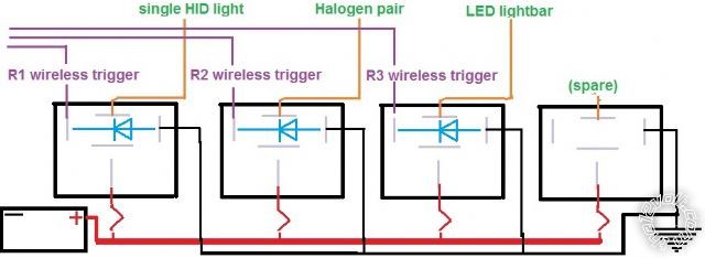
Okay! I think I'm on the right track here. Absolutely everything I know about diodes has been uploaded into my brain in the last 18 hours or so, so bear with me!
power distribution - Page 4 -- posted image.
OK, have to ask, what are you using for these diagrams- it could help me in both my hobbies and my work.
ronemca wrote:
But -- at the instant the coil is DE-energized -- there is residual energy in the coil that could theoretically cause problems. And the sudden discharge/collapse/burst of this residual energy is blocked/dissipated by the diode so that it cannot travel...to...where, exactly?
Apparently I am fuzzy on these, too- but I am pretty comfortable with this part of the theory:
Diode coils form an electromagnetic field, which is what actually does the physical work. Now, electromagnets and radio frequency are related (don't ask me to go into that, it gets pretty far into physics, and my head may explode!). When an electromagnetic (heretofor: "EM") field is rapidly collapsed without anywhere for the field to go (as in taking one side of the electrical field away), the energy is dispersed into an EMI (electromagnetic interference) burst (a very low-grade EMP <electromagnetic pulse> that can be coupled into any nearby components.
Comes down to it- the diodes don't so much protect the device which initiated the EMI burst (they do), but they also protect the other devices upon which they are installed.
This all would get us pretty deeply into physics, RF theory, and antenna theory believe it or not. Like many things in electronics, it's one of those things that you may not completely understand, you just have to shake your head and say "I believe" at some point, and proceed accordingly. Kinda like which direction current flows. ;)
ronemca wrote:
The trigger wire remains attached to the POS side of the relay all the time.
Not if you're using negative-trigger, it doesn't...
ronemca wrote:
And if the diode is wired in parallel across the coil terminals...it too is therefore attached to the trigger wire all the time.
Physically, yes.. but let's look at a pushbutton switch on the dash to activate the relay. When the relay is deactivated, the wire going to the switch is physically there, but neither going to ground nor +. It's literally detached from the electrical system.
burntkat 
Copper - Posts: 143
Copper spaceThis member has made a donation to the12volt.com. Click here for more info.spacespace
Joined: October 26, 2003
Location: South Carolina, United States
Posted: December 29, 2013 at 6:31 PM / IP Logged  
Going to start a new thread about diodes and my confusion therein. Please feel free to pipe up, guys...
Ween 
Platinum - Posts: 1,364
Platinum spacespace
Joined: August 01, 2004
Location: Illinois, United States
Posted: December 29, 2013 at 6:46 PM / IP Logged  
http://en.wikipedia.org /wiki/Flyback_diode
burntkat 
Copper - Posts: 143
Copper spaceThis member has made a donation to the12volt.com. Click here for more info.spacespace
Joined: October 26, 2003
Location: South Carolina, United States
Posted: December 29, 2013 at 6:55 PM / IP Logged  
burntkat wrote:
Ween wrote:
It would be a 1N400* series diode...1N4004 is fine. Connect the cathode (banded) side of the diode to the positive side of the coil, anode to the negative. On a bosch type relay, terminal 86 is typically the positive, terminal 85 the negative. More info can be seen here:
http://electronicsclub.info/diodes.htm
You might want to go back to diode school:
https://www.the12volt.com/ diodes/diodes.asp
I will of course recheck this with my DMM, but I went through this last night while building my system on the bench...
Please ignore the idiot that made the post questioning the post regarding the orientation of the diode. Ween is right of course.
I misread, misunderstood. I thought he was putting the cathode to the positive side to facilitate current flow (which of course would be wrong, as it won't flow in that direction, it's specifically there to BLOCK.. this is why they call it a BLOCKING diode, dummy!)
Sorry for the confusion. If it helps any, I think I got myself more confused than anyone.
ronemca 
Copper - Posts: 107
Copper spacespace
Joined: November 09, 2012
Location: Ontario, Canada
Posted: December 29, 2013 at 9:51 PM / IP Logged  
Despite having posted a few pics in this thread already...the pic I was trying to put into my last "wordy" post did not appear. I figured I had closed a window a bit too fast or something (and it hadn't had time to upload) so I tried posting it again in a post of its own. Nope - same outcome. And since I haven't made 50 posts...I cannot edit my posts. Anyway - (blah blah skin a cat...)
power distribution - Page 4 -- posted image.
I'm probably going to pick up the one for the flag terminals, but I noticed that some of the other styles appear identical but for the jaws (which are presumably replaceable) so I wrote to a couple of the sellers to ask if they sell jaws, and I'll just swap out the jaws depending upon my project.
Page of 13

  Printable version Printable version Post ReplyPost New Topic
You cannot post new topics in this forum
You cannot reply to topics in this forum
You cannot delete your posts in this forum
You cannot edit your posts in this forum
You cannot create polls in this forum
You cannot vote in polls in this forum

  •  
Search the12volt.com
Follow the12volt.com Follow the12volt.com on Facebook
Saturday, April 20, 2024 • Copyright © 1999-2024 the12volt.com, All Rights Reserved Privacy Policy & Use of Cookies
Disclaimer: *All information on this site ( the12volt.com ) is provided "as is" without any warranty of any kind, either expressed or implied, including but not limited to fitness for a particular use. Any user assumes the entire risk as to the accuracy and use of this information. Please verify all wire colors and diagrams before applying any information.

Secured by Sectigo
the12volt.com spacer
Support the12volt.com
Top
the12volt.com spacer