the12volt.com spacer
icon

wiring up my hei '74 401 cherokee


Post ReplyPost New Topic
< Prev Topic Next Topic >
berettajeep 
Member - Posts: 12
Member spacespace
Joined: April 18, 2014
Location: Oregon, United States
Posted: April 18, 2014 at 4:22 PM / IP Logged  
Okay I posted this on other websites but I am not getting much feedback as I would like. I remembered this site (and thought I joined many many moons ago but I guess not...)
I am Dennis. I am working with a 1974 Cherokee 401 stock points, stock alternator (for now), stock wiring (for now)
Searching on line I find numerous ideas and way things are done. I down loaded the factory wiring harness and took it to Staples and had them print it out on 11x17 card stock. I want to be sure what wires to change/ remove/ use before I actually start physically doing it. I will also be replacing fuse block with an EZ-wiring one and upgrading to the cs-144 alternator ( just not at this time)
Here is my stock wiring.
wiring up my hei '74 401 cherokee -- posted image.
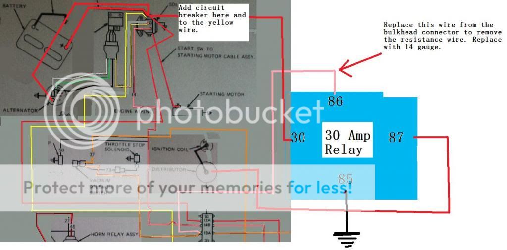
Here is what I would do.
wiring up my hei '74 401 cherokee -- posted image.
1) Remove the 10 gauge unfused interior feed from the alternator to the starter solenoid and add a 30 amp circuit breaker.
2) Already had a 2 gauge battery cable made, connect from the starter solenoid to alternator.
3) Remove the resistance wire by-pass that goes from the coil to the starter solenoid.
4)Remove the 20 gauge resistance wire from the bulkhead connector and replace the wire with a 14 gauge to feed #86 on the relay.
5)Run a 12 gauge wire from #87 on the relay to my Batt. on the new HEI.
6)Run a 12g wire to a 30 amp circuit breaker then to #30 on the relay.
7) ground #85 to the body.
8) Could I now remove the the 10g yellow wire that goes from the solenoid to the amp* gauge?
*I have already done the volt meter upgrade, is it possible to run that so it is not always on?
Please share opinions. I've been looking at this for days and one day it looks good to go and then another day I think it's totally wrong.
Are there pointless connections I am doing or something I forgot?
Thanks, Dennis
oldspark 
Gold - Posts: 4,913
Gold spacespace
Joined: November 03, 2008
Location: Australia
Posted: April 18, 2014 at 7:44 PM / IP Logged  
Can you explain what you are trying to do - ie, add or bypass or upgrade...?
Unfortunately I can't save the pics and even if clear enough I don't like working side-on.
oldspark 
Gold - Posts: 4,913
Gold spacespace
Joined: November 03, 2008
Location: Australia
Posted: April 18, 2014 at 8:02 PM / IP Logged  
PS - if it's to remove the IgCoil ballast aka resistor, simply bridge it (ie - short it out; wire from one end to the other) or remove it and join the 2 ends together, or connect its input (IGN +12V) end (the end NOT connected to the IgCoil) to your HEI +12V input and direct to the IgCoil "+" terminal (which was connected to the other end of the ballast).
The starter wire that was connected to the coil+ and ballast can be left disconnected - just insulate it so it does not connect or short to anything.
I suspect you are fitting a modern or HEI ignition which do not require internally ballasted (+12V) IgCoils nor ballasts fitted for later external-ballast (+8V) IgCoils.
In fact hopefully it will allow - and you will fit - a modern E-core type IgCoil. (Tho I'm using an old "typical" blue Nippon Denso IgCoil since it can cold start my vehicle with a very very flat battery (namely 6V).
Ween 
Platinum - Posts: 1,366
Platinum spacespace
Joined: August 01, 2004
Location: Illinois, United States
Posted: April 18, 2014 at 8:15 PM / IP Logged  
Hi,
If in the dash harness, the ignition feed at the bulkhead connector is large enough (14 gauge or better), why not use the same gauge lead to feed the HEI? If you have to use a relay, the resistance wire will adequately operate a bosch-type relay with no ill effects. A bosch-type relay is about 160mA, much less than an ignition coil.
For the charge lead with the stock system, the charge current is along the yellow wire. If removed, the battery won't charge. If bypassing the ammeter, the yellow wire would be jumped to the red at the ammeter. Or the alternator output could be connected to the starter solenoid battery junction point. This would be done with your high current (cs144) alternator upgrade, use an adequately sized wire. You could use the yellow wire as a voltage sense lead for the new alternator.
Connect the voltmeter positive to an ignition switch controlled fuse (gauges).
Mark
berettajeep 
Member - Posts: 12
Member spacespace
Joined: April 18, 2014
Location: Oregon, United States
Posted: April 18, 2014 at 8:28 PM / IP Logged  
oldspark wrote:
Can you explain what you are trying to do - ie, add or bypass or upgrade...?
Unfortunately I can't save the pics and even if clear enough I don't like working side-on.
I fixed the picture. Should be able to click on it to make it bigger.
What I am trying to accomplish is to remove the points system and replace with an HEI distributor. Also upgrade and remove wires I won't need.
berettajeep 
Member - Posts: 12
Member spacespace
Joined: April 18, 2014
Location: Oregon, United States
Posted: April 18, 2014 at 8:40 PM / IP Logged  
Ween wrote:
Hi,
If in the dash harness, the ignition feed at the bulkhead connector is large enough (14 gauge or better), why not use the same gauge lead to feed the HEI? If you have to use a relay, the resistance wire will adequately operate a bosch-type relay with no ill effects. A bosch-type relay is about 160mA, much less than an ignition coil.
For the charge lead with the stock system, the charge current is along the yellow wire. If removed, the battery won't charge. If bypassing the ammeter, the yellow wire would be jumped to the red at the ammeter. Or the alternator output could be connected to the starter solenoid battery junction point. This would be done with your high current (cs144) alternator upgrade, use an adequately sized wire. You could use the yellow wire as a voltage sense lead for the new alternator.
Connect the voltmeter positive to an ignition switch controlled fuse (gauges).
Mark
Mark I bypassed the old ammeter by moving the red and yellow wire together. Wanting to be able to see what my charging system is doing I replaced the ammeter with a volt meter. Right now both the yellow and red wires are going to the + side of the volt meter and I grounded the - post on the volt meter. Unfortunately even with the Jeep off, the volt meter shows what voltage the battery has.
I want to move the red wire from the back of the alternator to the ignition side of starter solenoid. Add a #1 battery cable from the starter solenoid to the back of the alternator
I'm not sure if I need to use a relay though, what would you recommend?
Ween 
Platinum - Posts: 1,366
Platinum spacespace
Joined: August 01, 2004
Location: Illinois, United States
Posted: April 18, 2014 at 9:01 PM / IP Logged  
Shouldn't be too hard to locate a switched power source under the dash.
The alternator output (heavy gauge) wire needs to connect to either the positive battery terminal or the previously mentioned starter solenoid terminal (battery side).
Not familiar with the AMC/Jeep wiring harness, but if the wire is 14 gauge or larger, that should be more than adequate for an HEI ignition system.
The relay adds complexity to the circuit.
oldspark 
Gold - Posts: 4,913
Gold spacespace
Joined: November 03, 2008
Location: Australia
Posted: April 18, 2014 at 9:58 PM / IP Logged  
Cool... glad I clicked (ie, my PS). Sorry - I'm feeling groggy after some (drug & alcohol free) days away camping.
I endorse what Ween wrote - you should be able to power your HEI from the existing wire to the IgCoil ballast. That's IGN +12V.
Where I thought that wire was too small - or if I thought Ign or HEI noise injected back thru the wire to the IGN switch etc might cause unwanted noise and interference - I'd use the wire to turn on a typical automotive 30A relay (86 with 85 to GND) to connect the HEI +12V and igCoil+ (else igCoil's ballast resistor) to the battery - ie, 30 & 87 - with a suitable fuse (usually at least 15A, maybe 30A - but equal to or less than what current the wire and relay could handle).
You do not want to interrupt the alternator +12V output (usually called B or B+) to the battery +12V since that can cause electrical damage - especially on older alternators with external regulators.
[ Older alternators could go way over +16V without a battery connected. Newer alternators may limit their output to under 16V but without a battery connected there is nothing to filter +12V noise (switching relays, motors, etc) and voltage spikes can damage equipment, and furthermore the engine is likely to stall if there is a step change like flashers or brake lights etc. ]
I often recommend upgrading older external regulated alternators to modern alternators with integral regulators (specifically those with a dedicated "Sense" wire that goes straight to the battery +12V) since they exhibit far superior behaviour and overcome problems that can occur with external voltage regulators (eg, loss of or bad GNDs).
If the old system works then leave it. But when problems appear, IMO forget the common tail-chasing scenario of replacing the regulator, then the alternator, then the regulator again, and then BOTH the alternator & regulator and replace the lot with an all in one modern alternator.
They merely have to physically fit (with aligned belt) and have at least the required output (Amps).
The wiring is usually easy... Upgrade the heavy B/B+ to battery +12V (maybe with a fuse close to the battery +12V which is to protect the battery & cable from a cable short - it rarely protects the alternator). Connect the L (or D+) charge light wire to the existing circuit - eg, into the appropriate pin/terminal of the old requlator's main harness connector. And connect the S (Sense) wire direct to the battery +12V terminal (that can be fused else merely use a thin cable which won't cause damage if it shorts & fuses).
If they also have an I or IGN terminal, that can also probably go to the old regulator's harness connector, or your igCoil +12V (igCoil+) etc - though most alternators are usually only S&L types and no longer use a dedicated I or Ig or IGN +12V signal, else only have the L = charge light known as D+ (but I usually recommend S&L types rather than the D+ only types).   
Apologies if that's a lot of detail, but I hope it helps.
If unclear, please ask.
And I'd probably consider your own separate wiring. I haven't been impressed with the wiring of more recent Jeeps and I dread to think of Jeeps that are more than 20 years older....
oldspark 
Gold - Posts: 4,913
Gold spacespace
Joined: November 03, 2008
Location: Australia
Posted: April 18, 2014 at 10:08 PM / IP Logged  
Some additional stuff.
Ammeters are essentially useless. And certainly those without external shunts - ie, those that drag the (alternator to) battery cable thru the cabin are stupid, and hazardous.
A 3 digit (dash mounted) voltmeter across the battery terminals will tell you all you need to know about your charging system, and probably your battery health too.
My dash voltmeter is connected to batt +12V via a small (1A) relay actuated by IGN +12V. (Tho I have long intended to add a manual switch as well as some hold-on delays to control that relay.)
Hopefully your HEI is a good unit. I recommend reluctor sensors (new generation with single lobes and a single self contained sensor) feeding suitable ignitors.
IMO the best ignition system (ignitor) is CDI tho I ceased building my cheap sequential spark CDI after finding out just how good my 'more modern' 1980's vintage reluctor & ignitor and igCoil was.
PS - bypass the ammeter wiring with the alternator output direct to the battery +12V else the starter-motor's heavy input - or as some vehicles do, to the main fusebox +12V etc.
But IMO alternator direct to battery +12V is best - provided it's easy to do. That should be the shortest run.
Remember that the alternator should be supplying the correct voltage for the battery - ie, not too low, and in general not above 14.4V longterm for a typical flooded/wet cell battery.
Voltage drops along the alternator-battery current path can cause problems tho S-terminal Sensing regulators (alternators) overcome that from the battery's POV, but that may mean higher voltages elsewhere if it's not a direct alt-batt connection.
howie ll 
Pot Metal - Posts: 16,466
Pot Metal spacespace
Joined: January 09, 2007
Location: United Kingdom
Posted: April 19, 2014 at 6:31 AM / IP Logged  
Don't know if anyone else mentioned this but AFAIK concerned the voltmeter is part, i.e. wired in parallel to the ignition circuit.
Otherwise absolutely agree with everything Oldspark and Ween suggest, also that the ammeter is useless, BTW if you keep it, the ammeter should use 5 gauge or even thicker wiring and be in series from the battery for everything bar starter and alternator leads.
Page of 3

  Printable version Printable version Post ReplyPost New Topic
You cannot post new topics in this forum
You cannot reply to topics in this forum
You cannot delete your posts in this forum
You cannot edit your posts in this forum
You cannot create polls in this forum
You cannot vote in polls in this forum

  •  
Search the12volt.com
Follow the12volt.com Follow the12volt.com on Facebook
Tuesday, April 23, 2024 • Copyright © 1999-2024 the12volt.com, All Rights Reserved Privacy Policy & Use of Cookies
Disclaimer: *All information on this site ( the12volt.com ) is provided "as is" without any warranty of any kind, either expressed or implied, including but not limited to fitness for a particular use. Any user assumes the entire risk as to the accuracy and use of this information. Please verify all wire colors and diagrams before applying any information.

Secured by Sectigo
the12volt.com spacer
Support the12volt.com
Top
the12volt.com spacer