


one button push button start relay system


Posted: April 21, 2014 at 6:56 PM / IP Logged
 That (^) is my current setup right now, it's simple, I just use a switch to control the ground for the IG1, IG2, and ACC relays and then the momentary push button controls the starter. I also incorporated my rfid's starter kill as well as the brake wire into my starter relay.
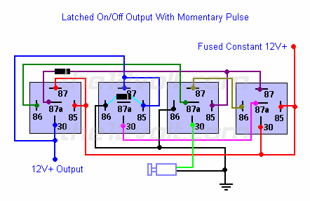
What I'm wanting to do is use the latching on/off relay diagram from this site to create a one button push to start system that will turn the acc/ign on with one push, another push will start the car and a third push will turn the acc/ign off. I'd incorporate my rfid starter kill output by using a normally closed relay that would provide the ground to the other relays when the system is disarmed and then would remove the ground when the system is armed. The thing I'm having trouble with is how to add the additional starter control feature to the same button in this diagram.
That (^) is my current setup right now, it's simple, I just use a switch to control the ground for the IG1, IG2, and ACC relays and then the momentary push button controls the starter. I also incorporated my rfid's starter kill as well as the brake wire into my starter relay.
What I'm wanting to do is use the latching on/off relay diagram from this site to create a one button push to start system that will turn the acc/ign on with one push, another push will start the car and a third push will turn the acc/ign off. I'd incorporate my rfid starter kill output by using a normally closed relay that would provide the ground to the other relays when the system is disarmed and then would remove the ground when the system is armed. The thing I'm having trouble with is how to add the additional starter control feature to the same button in this diagram.
 Thanks for any help you guys may be able to provide
Brandon
Thanks for any help you guys may be able to provide
Brandon
Posted: April 21, 2014 at 6:59 PM / IP Logged

Posted: April 24, 2014 at 8:19 PM / IP Logged
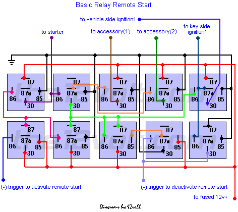 There's a lot going on in this circuit. But there are two things you can use:
"Activate remote start" trigger holds the starter engaged for as long as the (-) input is applied.
The "accy 1 and 2" relays are DE-energized during cranking. You may not need this, and one relay can be eliminated. But the same 'button push' that activates the starter, also turns on IGN and ACCY.
This circuit has two different triggers. One to activate, and one to deactivate it. The latch on, latch off circuit you found above has 2 relays that 'flop' the single input between 'on' and 'off'. These are the right hand two relays in the diagram. It would be simple to incorporate the 'flip flop' relays into the latching 'remote start' array.
The one thing I haven't mentioned is a button-activated "ACCY" position. Perhaps a hidden switch for ACCY-only for the occasions you want to listen to the radio with the engine off.
Study these circuits. I think you will easily figure out how to make what you want from the pair of circuits.
There's a lot going on in this circuit. But there are two things you can use:
"Activate remote start" trigger holds the starter engaged for as long as the (-) input is applied.
The "accy 1 and 2" relays are DE-energized during cranking. You may not need this, and one relay can be eliminated. But the same 'button push' that activates the starter, also turns on IGN and ACCY.
This circuit has two different triggers. One to activate, and one to deactivate it. The latch on, latch off circuit you found above has 2 relays that 'flop' the single input between 'on' and 'off'. These are the right hand two relays in the diagram. It would be simple to incorporate the 'flip flop' relays into the latching 'remote start' array.
The one thing I haven't mentioned is a button-activated "ACCY" position. Perhaps a hidden switch for ACCY-only for the occasions you want to listen to the radio with the engine off.
Study these circuits. I think you will easily figure out how to make what you want from the pair of circuits.Posted: April 26, 2014 at 9:17 PM / IP Logged
Posted: October 28, 2014 at 11:58 PM / IP Logged
Sorry, you can NOT post a reply.
This topic is closed.
 Printable version
| You cannot post new topics in this forum You cannot reply to topics in this forum You cannot delete your posts in this forum You cannot edit your posts in this forum You cannot create polls in this forum You cannot vote in polls in this forum |

| Search the12volt.com |
Follow the12volt.com 
Thursday, April 25, 2024 • Copyright © 1999-2024 the12volt.com, All Rights Reserved • Privacy Policy & Use of Cookies

Thursday, April 25, 2024 • Copyright © 1999-2024 the12volt.com, All Rights Reserved • Privacy Policy & Use of Cookies
Disclaimer:
*All information on this site ( the12volt.com ) is provided "as is" without any warranty of any kind, either expressed or implied, including but not limited to fitness for a particular use. Any user assumes the entire risk as to the accuracy and use of this information. Please
verify all wire colors and diagrams before applying any information.
