the12volt.com spacer
icon

stuck on relay for horn


Post ReplyPost New Topic
< Prev Topic Next Topic >
nat28 
Member - Posts: 32
Member spacespace
Joined: July 15, 2014
Posted: August 30, 2014 at 12:57 PM / IP Logged  
howie ll wrote:
Yes, quite correct.
Thank you.
2013 Subaru Outback Limited
2005 Toyota Sequoia
the12volt 
Administrator - Posts: 3,955
Administrator spaceThis member has made a donation to the12volt.com. Click here for more info.spaceThis member has been recognized as an authority in Electrical Theory. Click here for more info.spaceThis member has been recognized as an authority in Mobile Audio and Video. Click here for more info.spaceThis member has been recognized as an authority in Mobile Security and Convenience. Click here for more info.spacespace
Joined: March 07, 2002
Location: Louisiana, United States
Posted: August 30, 2014 at 1:44 PM / IP Logged  
Other than supplying 12V+ to 86 instead of 85 and switch to 85 instead of 86, your diagram and howie's suggestion is exactly what I told you to do. The confusion may come from the red line you had drawn in your first diagram from the switch to the relay, which regardless of the color wire used, the switch was still(already) sending ground to one side of the coil of the relay.
stuck on relay for horn - Page 2 -- posted image. the12volt • Support the12volt.com
nat28 
Member - Posts: 32
Member spacespace
Joined: July 15, 2014
Posted: August 30, 2014 at 3:34 PM / IP Logged  
the12volt wrote:
Other than supplying 12V+ to 86 instead of 85 and switch to 85 instead of 86, your diagram and howie's suggestion is exactly what I told you to do. The confusion may come from the red line you had drawn in your first diagram from the switch to the relay, which regardless of the color wire used, the switch was still(already) sending ground to one side of the coil of the relay.
Relays are new to me. Sorry I misunderstood. Thanks.
2013 Subaru Outback Limited
2005 Toyota Sequoia
oldspark 
Gold - Posts: 4,913
Gold spacespace
Joined: November 03, 2008
Location: Australia
Posted: August 30, 2014 at 7:58 PM / IP Logged  
Nat, keep in mind than an "x" V device needs xV to work.
IE - a 12V relay needs 12V across its coil to operate, hence one end to +12V & the other to 0V (ie, battery -ve terminal, GND etc).
The same is true for bulbs etc. (They are connected in parallel with the supply tho that may not be obvious unless you connect more than one load - ie a few 12V bulbs or relays.)
nat28 
Member - Posts: 32
Member spacespace
Joined: July 15, 2014
Posted: August 30, 2014 at 10:45 PM / IP Logged  
oldspark wrote:
Nat, keep in mind than an "x" V device needs xV to work.
IE - a 12V relay needs 12V across its coil to operate, hence one end to +12V & the other to 0V (ie, battery -ve terminal, GND etc).
The same is true for bulbs etc. (They are connected in parallel with the supply tho that may not be obvious unless you connect more than one load - ie a few 12V bulbs or relays.)
Oldspark, pardon my ignorance. Which numbers indicate the ends of the relay? And 0V means ground/-terminal?
2013 Subaru Outback Limited
2005 Toyota Sequoia
oldspark 
Gold - Posts: 4,913
Gold spacespace
Joined: November 03, 2008
Location: Australia
Posted: August 30, 2014 at 11:47 PM / IP Logged  
See the Relays link above.
But the coil is 85 & 86 with 86 being the most +ve by convention (in case you use a relay with inbuilt diode to quench the coil spark) - as per previous replies.
30, 87 & 87a are the usual "power" = heavy current switching terminals.
30 to 87 are NO = Normally Open and close (make contact, ie, connect) when the coil is energised (12V across it).
NOTE - "Normally" refers to as it/they are when siting on the shelf unused (unless defined otherwise).
30 to 87a are NC = normally closed if 87a exists - ie, SPST (4-pin) relays have 30 & 87 only; SPDT have changeover contacts; 30 goes either to 87 else 87a. Also called 5-pin, but a warning - some 5 pin relays have two 87 contacts.
30 is usually called the power-in terminal but for simple on-off (SPST) using only 30 & 87 it shouldn't matter.
And in some cases 30 is the output with 87 & 87a as inputs (eg, dynamic braking (wiper) motors etc).
Sorry if that's too much info, but that should cover all the basics.
Incidentally, most of us buy SPDT relays and simply don't use 87a if only SPST (4 pin) functionality is needed. Therefore one relay type can replace both - provided the mounting socket allows for it, and provided there isn't substantial cost penalty. (But since most SPST relays are manufactured as SPDT but with the 87a terminal shorn off....)
0V means ground.
Back in the olde days, 12V supplies were often labelled as +12V & -12V, but that really means a 24V supply. Not that it mattered much until OpAmps and amplifier circuits became common and they do use +12V & -12V and a 0V "gnd".
Hence nowadays the battery minus terminal is called 0V or ground or earth or chassis etc. (Except for +ve earth/gnd vehicles where you have 0V & -12V (or -6V for really old vehicles), but they usually called -6V or -12V simply 6V or 12V respectively, else the "hot side".)
Does that help, or confuse?
And there is nothing magic about relays... They are merely remote switches, or (digital) "amplifiers". IE - a small current and switch can connect a big current (elsewhere).   
They do have other uses like polarity conversion (change a +12V signal to 0V) and system isolation (a 12V relay switches a 24V or 110VAC load) as well as logic circuits.
nat28 
Member - Posts: 32
Member spacespace
Joined: July 15, 2014
Posted: August 31, 2014 at 6:17 AM / IP Logged  
oldspark wrote:
See the Relays link above.
But the coil is 85 & 86 with 86 being the most +ve by convention (in case you use a relay with inbuilt diode to quench the coil spark) - as per previous replies.
30, 87 & 87a are the usual "power" = heavy current switching terminals.
30 to 87 are NO = Normally Open and close (make contact, ie, connect) when the coil is energised (12V across it).
NOTE - "Normally" refers to as it/they are when siting on the shelf unused (unless defined otherwise).
30 to 87a are NC = normally closed if 87a exists - ie, SPST (4-pin) relays have 30 & 87 only; SPDT have changeover contacts; 30 goes either to 87 else 87a. Also called 5-pin, but a warning - some 5 pin relays have two 87 contacts.
30 is usually called the power-in terminal but for simple on-off (SPST) using only 30 & 87 it shouldn't matter.
And in some cases 30 is the output with 87 & 87a as inputs (eg, dynamic braking (wiper) motors etc).
Sorry if that's too much info, but that should cover all the basics.
Incidentally, most of us buy SPDT relays and simply don't use 87a if only SPST (4 pin) functionality is needed. Therefore one relay type can replace both - provided the mounting socket allows for it, and provided there isn't substantial cost penalty. (But since most SPST relays are manufactured as SPDT but with the 87a terminal shorn off....)
0V means ground.
Back in the olde days, 12V supplies were often labelled as +12V & -12V, but that really means a 24V supply. Not that it mattered much until OpAmps and amplifier circuits became common and they do use +12V & -12V and a 0V "gnd".
Hence nowadays the battery minus terminal is called 0V or ground or earth or chassis etc. (Except for +ve earth/gnd vehicles where you have 0V & -12V (or -6V for really old vehicles), but they usually called -6V or -12V simply 6V or 12V respectively, else the "hot side".)
Does that help, or confuse?
And there is nothing magic about relays... They are merely remote switches, or (digital) "amplifiers". IE - a small current and switch can connect a big current (elsewhere).   
They do have other uses like polarity conversion (change a +12V signal to 0V) and system isolation (a 12V relay switches a 24V or 110VAC load) as well as logic circuits.
Thanks for the help. For whatever reason, relays do confuse me! I understand that they are an electromagnetic switch, but the variable configurations for wiring them can leave my head spinning! I think part of the problem is that the very simply diagrams that show how the actual relay conducts electricity label the poles 1, 2, 3, 4 rather than 30, 85, 86, 87.
Apparently I do have SPDT relays since mine do have the 87a pole.
In comparing your reply with my revised diagram, I think I'm okay, right?
Thanks again.
2013 Subaru Outback Limited
2005 Toyota Sequoia
howie ll 
Pot Metal - Posts: 16,466
Pot Metal spacespace
Joined: January 09, 2007
Location: United Kingdom
Posted: August 31, 2014 at 6:22 AM / IP Logged  
Ignore an convention that uses 123 etc.
ISO convention.
85 = coil NEG (-)
86 = coil POS (+)
87 = NO normally open
87a = NC normally closed
30 = common
In other words, at rest 87a (if present is connected to 30.
On energising the coil (think of that as throwing a switch), 87 becomes connected to 30 and 87a is disconnected.
oldspark 
Gold - Posts: 4,913
Gold spacespace
Joined: November 03, 2008
Location: Australia
Posted: August 31, 2014 at 7:54 AM / IP Logged  
Fear not Nat, you are not alone.
But for now, forget all those "complex" wirings. As Howard said, you flip a switch which provides (say) 12V to the coil hence magnetising it and pulling the "swinging contact" 30 to 87. Yes, it's an electro-magnetic switch.
And tho Howard says "ignore the 123s" etc, the new micro-DIN relays use 1-5 (eg 1 & 2 are coil; generally 1 = +ve = 86; 2 = -ve = 85) and other relays can use whatever.
I hate the physical digramatic depiction of relays. I prefer the line or circuit diagrams, eg:
(Try to ignore the diodes, and the notes. I'm merely using a pair of my easy to find pics. FYI - they are for pumping water etc out of a bilge or sump, or to keep a tank topped up.)
(And oops - the top diagram does not include the OFF switch shown in the lower diagram.)    
stuck on relay for horn - Page 2 -- posted image.
... as opposed to ...
stuck on relay for horn - Page 2 -- posted image.
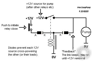
Tho the top "circuit" diagram is not that clear, IMO that or similar are easier to follow because you see the contacts, and coil, and how they connect.
I NEVER used relay pin/terminal numbers in diagrams since I did not want to limit to DIN relays (Bosch, Hella etc using pins 30, 87, 86, 85 etc).
In fact I never learned those labels until I started on the12volt. (And even that was after a few years after deciding it was easier memorising them than forever looking them up.)
But because (almost?) all DIN relays have a diagram with pin numbers on them, I found it easy using them in practice despite unlabelled circuit diagram pin numbers.   
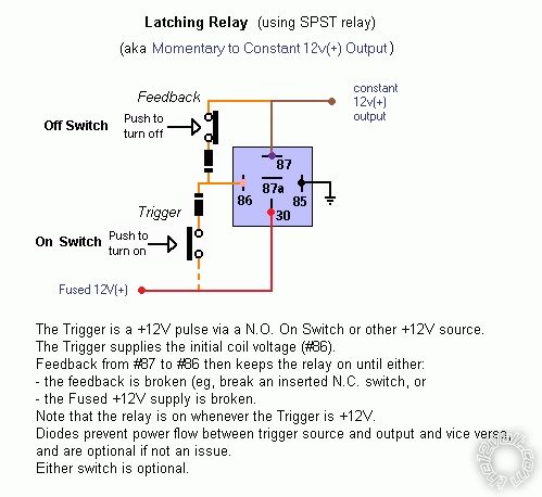
And if I used my normal JIDEC (Jap) or other relays, I never had to convert pin mumbers on "wiring diagrams" (as per the lower diagram above). Of course I'd have to know the relay's "circuit" relationship to its pin numbers, but they too usually had a schematic or diagram on their body; otherwise I'd have to look at their datasheets etc.
IMO the wiring or "physical" diagrams are good for those that simply want to wire & build. But if you want to understand or fault find, or be able to use different relays, then IMO circuit diagrams are essential.
And now I've probably confused you even more...
But I now use micro-DIN relays instead of the mini-DIN relays (aka cube type as used on the12volt) so translating 30 & 87 etc is a bit of a pain.
nat28 
Member - Posts: 32
Member spacespace
Joined: July 15, 2014
Posted: August 31, 2014 at 8:32 AM / IP Logged  
howie ll wrote:
Ignore an convention that uses 123 etc.
ISO convention.
85 = coil NEG (-)
86 = coil POS (+)
87 = NO normally open
87a = NC normally closed
30 = common
In other words, at rest 87a (if present is connected to 30.
On energising the coil (think of that as throwing a switch), 87 becomes connected to 30 and 87a is disconnected.
Thanks. This sentence "On energising the coil (think of that as throwing a switch), 87 becomes connected to 30 and 87a is disconnected." is making sense now.
2013 Subaru Outback Limited
2005 Toyota Sequoia
Page of 3

  Printable version Printable version Post ReplyPost New Topic
You cannot post new topics in this forum
You cannot reply to topics in this forum
You cannot delete your posts in this forum
You cannot edit your posts in this forum
You cannot create polls in this forum
You cannot vote in polls in this forum

  •  
Search the12volt.com
Follow the12volt.com Follow the12volt.com on Facebook
Thursday, April 25, 2024 • Copyright © 1999-2024 the12volt.com, All Rights Reserved Privacy Policy & Use of Cookies
Disclaimer: *All information on this site ( the12volt.com ) is provided "as is" without any warranty of any kind, either expressed or implied, including but not limited to fitness for a particular use. Any user assumes the entire risk as to the accuracy and use of this information. Please verify all wire colors and diagrams before applying any information.

Secured by Sectigo
the12volt.com spacer
Support the12volt.com
Top
the12volt.com spacer