Posted: August 31, 2014 at 8:34 AM / IP Logged
Posted: August 31, 2014 at 8:50 AM / IP Logged
Posted: August 31, 2014 at 10:05 AM / IP Logged
Posted: August 31, 2014 at 10:07 AM / IP Logged
Sorry, you can NOT post a reply.
This topic is closed.
 Printable version


| You cannot post new topics in this forum You cannot reply to topics in this forum You cannot delete your posts in this forum You cannot edit your posts in this forum You cannot create polls in this forum You cannot vote in polls in this forum |

| Search the12volt.com |
Follow the12volt.com 
Tuesday, April 16, 2024 • Copyright © 1999-2024 the12volt.com, All Rights Reserved • Privacy Policy & Use of Cookies


Tuesday, April 16, 2024 • Copyright © 1999-2024 the12volt.com, All Rights Reserved • Privacy Policy & Use of Cookies
Disclaimer:
*All information on this site ( the12volt.com ) is provided "as is" without any warranty of any kind, either expressed or implied, including but not limited to fitness for a particular use. Any user assumes the entire risk as to the accuracy and use of this information. Please
verify all wire colors and diagrams before applying any information.


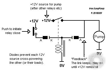
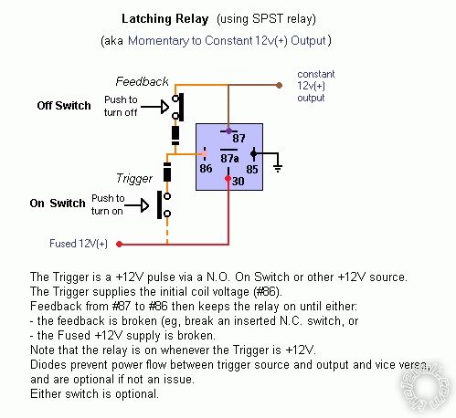
 ... as opposed to ...
 Tho the top "circuit" diagram is not that clear, IMO that or similar are easier to follow because you see the contacts, and coil, and how they connect.
I NEVER used relay pin/terminal numbers in diagrams since I did not want to limit to DIN relays (Bosch, Hella etc using pins 30, 87, 86, 85 etc).
In fact I never learned those labels until I started on the12volt. (And even that was after a few years after deciding it was easier memorising them than forever looking them up.)
But because (almost?) all DIN relays have a diagram with pin numbers on them, I found it easy using them in practice despite unlabelled circuit diagram pin numbers.
And if I used my normal JIDEC (Jap) or other relays, I never had to convert pin mumbers on "wiring diagrams" (as per the lower diagram above). Of course I'd have to know the relay's "circuit" relationship to its pin numbers, but they too usually had a schematic or diagram on their body; otherwise I'd have to look at their datasheets etc.
IMO the wiring or "physical" diagrams are good for those that simply want to wire & build. But if you want to understand or fault find, or be able to use different relays, then IMO circuit diagrams are essential.
And now I've probably confused you even more...
But I now use micro-DIN relays instead of the mini-DIN relays (aka cube type as used on the12volt) so translating 30 & 87 etc is a bit of a pain.


