the12volt.com spacer
icon

acc + ign.sw viper-omegalink


Post ReplyPost New Topic
< Prev Topic Next Topic >
mediaman 
Member - Posts: 21
Member spacespace
Joined: November 05, 2014
Location: Illinois, United States
Posted: November 17, 2014 at 12:37 PM / IP Logged  
I NEED TO KNOW IF ACC+ SIGNAL FROM IGNITION SWITCH NEEDS TO CONNECT TO VIPER 4806V, THE BYPASS MODULE OL-AL(MDB)-GM2 DOCUMENT #8871 SHOWS THAT IT DOES.BUT,THEIR DRAWING SHOWS A GENERIC REMOTE STARTER.
THANK YOU.
1616884422
kreg357 
Platinum - Posts: 7,783
Platinum spaceThis member has made a donation to the12volt.com. Click here for more info.spaceThis member has been recognized as an authority in Electrical Theory. Click here for more info.spaceThis member has been recognized as an authority in Mobile Security and Convenience. Click here for more info.spacespace
Joined: January 30, 2009
Location: Pennsylvania, United States
Posted: November 17, 2014 at 6:28 PM / IP Logged  

Absolutely.

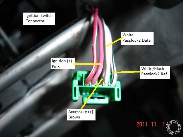
acc + ign.sw viper-omegalink -- posted image.

Soldering is fun!
mediaman 
Member - Posts: 21
Member spacespace
Joined: November 05, 2014
Location: Illinois, United States
Posted: November 18, 2014 at 12:48 PM / IP Logged  
Thank You, I believe that it would be connected to the "Remote Start,8-pin connector" but not clear of how. It appears as well, that pins 1,4 and 7 of the same connector would tie together and go to constant 12v., is that correct ? I would appreciate if you would clear all that up for me.
Thanks,again.
1616884422
mediaman 
Member - Posts: 21
Member spacespace
Joined: November 05, 2014
Location: Illinois, United States
Posted: November 18, 2014 at 1:40 PM / IP Logged  
PLEASE CORRECT ME IF I'M WRONG.I BELIEVE IT'S PIN 6 ORANGE(+)ACC.OUTPUT TO FEED IGN. SW. ACC+   ,AND PIN 5 VIOLET(+) STARTER OUTPUT GOES TO IGN.SW.START WIRE. AND 1,4 AND 7 PROVIDES THE HOT FOR THE RELAYS.
1616884422
kreg357 
Platinum - Posts: 7,783
Platinum spaceThis member has made a donation to the12volt.com. Click here for more info.spaceThis member has been recognized as an authority in Electrical Theory. Click here for more info.spaceThis member has been recognized as an authority in Mobile Security and Convenience. Click here for more info.spacespace
Joined: January 30, 2009
Location: Pennsylvania, United States
Posted: November 18, 2014 at 7:30 PM / IP Logged  

4806V  Remote Start, 8-pin connector

1 RED / BLACK (+) 12VDC INPUT for ACC & starter       +12V Constant
2 PINK/BLACK (+) FLEX RELAY INPUT 87A     not used
3 PINK/WHITE (+) IGNITION 2 / FLEX OUTPUT not used
4 RED (+) 12VDC INPUT for ignition 1 +12V constant
5 VIOLET (+) STARTER OUTPUT         not used
6 ORANGE (+) ACCESSORY OUTPUT to Green 6 pin plug, Pin 4 Brown (+) Ignition switch ***
7 RED / WHITE (+) 12VDC INPUT for Flex           not used
8 PINK (+) IGNITION 1 INPUT/OUTPUT   to Green 6 pin plug, Pin 3 Pink (or Yellow) (+) Ignition switch
***  Also goes to OL-AL(MDB)-GM2 BLACK/ White Accessory Input wire

There is no vehicle ignition "Starter wire" at the main ignition switch harness. 

There is no vehicle need for the Viper Flex Relay Pink/White wire and therefore no need to connect the RED / White wire to

+12V constant ( won't hurt to connect it but...).

The vehicles White wire at Pin 5 of the ignition switch is actually a MUX wire and is controller by the bypass module.

Therefore, no direct connections from the Viper to this wire.  Follow the above Remote Start, 8-pin connector wiring
listed.

Soldering is fun!
mediaman 
Member - Posts: 21
Member spacespace
Joined: November 05, 2014
Location: Illinois, United States
Posted: November 18, 2014 at 7:56 PM / IP Logged  
Sounds good,ignition switch pin 5 on doc.#8871, type 2 wiring from Omegalink, shows it to be Passlock and wire is cut.Then bypass module ,WTE/BLK to IGN.SW. connector and WTE/RED spliced with YEL. goes to the cut wire to the vehicle side.They also show +12v power to ignition switch pin 2.Shouldn't I take all constant +12v from BCMx3,+12V. 50AMP RED / blk WIRE ?
Thank You.
1616884422
kreg357 
Platinum - Posts: 7,783
Platinum spaceThis member has made a donation to the12volt.com. Click here for more info.spaceThis member has been recognized as an authority in Electrical Theory. Click here for more info.spaceThis member has been recognized as an authority in Mobile Security and Convenience. Click here for more info.spacespace
Joined: January 30, 2009
Location: Pennsylvania, United States
Posted: November 18, 2014 at 8:01 PM / IP Logged  
i need to know if acc+ signal from ignition switch needs to connect to viper 4806v, the bypass module ol-al(mdb)-gm2 document #8871 shows that it does.but,their drawing shows a generic remote starter.
thank you.
Soldering is fun!
mediaman 
Member - Posts: 21
Member spacespace
Joined: November 05, 2014
Location: Illinois, United States
Posted: November 18, 2014 at 8:24 PM / IP Logged  
What do you think about the below wiring ?
Ignition switch pin 5 on doc.#8871, type 2 wiring from Omegalink, shows it to be Passlock and wire is cut.Then bypass module ,WTE/BLK to IGN.SW. connector and WTE/RED spliced with YEL. goes to the cut wire to the vehicle side.
1616884422
mediaman 
Member - Posts: 21
Member spacespace
Joined: November 05, 2014
Location: Illinois, United States
Posted: November 18, 2014 at 8:27 PM / IP Logged  
I see you already mentioned that it's controlled by the Bypass module but they don't refer it by MUX
1616884422
kreg357 
Platinum - Posts: 7,783
Platinum spaceThis member has made a donation to the12volt.com. Click here for more info.spaceThis member has been recognized as an authority in Electrical Theory. Click here for more info.spaceThis member has been recognized as an authority in Mobile Security and Convenience. Click here for more info.spacespace
Joined: January 30, 2009
Location: Pennsylvania, United States
Posted: November 18, 2014 at 8:54 PM / IP Logged  
Yes, it is described as Passlock but it does a couple of functions.  Take a look at DEI TechTip 1605 to see what
the bypass modules is really doing to that White wire.  Here is a link to a ZIP file that includes Tech Tip 1605 :
https://www.the12volt.com/installbay/file.asp?ID=1080 
Soldering is fun!
Page of 2

  Printable version Printable version Post ReplyPost New Topic
You cannot post new topics in this forum
You cannot reply to topics in this forum
You cannot delete your posts in this forum
You cannot edit your posts in this forum
You cannot create polls in this forum
You cannot vote in polls in this forum

  •  
Search the12volt.com
Follow the12volt.com Follow the12volt.com on Facebook
Tuesday, April 23, 2024 • Copyright © 1999-2024 the12volt.com, All Rights Reserved Privacy Policy & Use of Cookies
Disclaimer: *All information on this site ( the12volt.com ) is provided "as is" without any warranty of any kind, either expressed or implied, including but not limited to fitness for a particular use. Any user assumes the entire risk as to the accuracy and use of this information. Please verify all wire colors and diagrams before applying any information.

Secured by Sectigo
the12volt.com spacer
Support the12volt.com
Top
the12volt.com spacer