Keep in mind I don't know the answer - I've become like others that would rather spend hours & pages & delays debating rather than a 2-5 minute google search. (That's how we modern people keep ourselves too busy to have time for priorities.)
But IMO my "half current = half speed" meaning no drop in power consumption is valid.
However if half speed is a combination of voltage & current, then the PWM does save power - ie, it is not wasting the power in (heat from) the resistor.
Certainly PWM is the most efficient method normally. It replaces other "dropping" methods that involve dissipating power.
And for things like LEDs it is the only way to dim in proportion to a control signal (eg a pot or voltage). (Although a variable constant current feed could be used, but not for several parallel LED strings, or if mixed with incandescent bulbs etc.)
I do now recall when building an AC motor speed controller way back last millennium (using phase controlled triacs or SCRs but essentially the same as PWM) that the source blurb referred to high or good torque at low RPM. In retrospect - namely now LOL - I reckon that must have been in comparison to alternate resistive methods.
Torque versus power - now that's a tricky thing. But I know and can
picture how my 400Nm 2 litre 45 year old car (135HP - I mean, 100kW) beat the crap out of 400HP V8s & rotaries & WRXs etc. (And I'm sick of telling people that an increase in engine power does not mean a heavier clutch and transmission - that is only needed if peak torque increases.) However I have little memory of electric motor torque (other than old steam cranes can get heavier things off the ground than modern electric etc cranes).
Earlier than the drill/motor speed controller I fitted a dimmer to fluorescent lights. (That was when I was 15 years young but yes, I still strike people that claim it's impossible to dim fluoros!). That has to use phase control (not unlike PWM wrt current) to "merely" reduce the current but not the (peak) voltage - just like LEDs - tho AC fluoros require a filament transformer to maintain the high firing voltage. (The transformer replaced the fluoro ballast & starter. And we never replaced a fluoro after that except when they aged & lost brightness - in our case after 15 years. And kids had fun looking at the blue & white
ripples traveling along the tube at lowest brightness.)
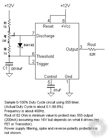
I even used a PWM (the earlier 555 circuit) for a mate's stationwagon's 12V flouro tube. That makes me think PWM can be used to dim HIDs etc but that depends on their
ballast circuit - modern day ballasts tend to be more electronic than the older ferro-magnetic (transformer) inverters and devices, and some will not tolerate a dimming signal. (hence why some AC LEDs and CFLs are dimmable whereas others aren't).
And FYI, recently I reinforced that voltage cannot be used to dim LED arrays...
I fitted a 3rd brake LED bar to my ute which I also wanted to act like a 3rd taillight. Instead of making a PWM I used a small dc-dc converter (thumbnail sized; ~$3 off eBay). I think it was ~8V (7.6V?) for the correct brightness. However I found that sometimes some LEDs would be dimmer of unlit - or occasionally brighter - in groups of 3 - the bar consisted of about 11 parallel strings of 3 series white LEDs.) At first I thought the darkies were blown but they proved ok. Temperature effected the LED characteristics and being like Zener diodes they'd take current from other strings. So yet again substituting voltage control for PWM was the solution.
Incidentally, both solutions are equally efficient electrically. A dc-dc voltage regulator/converter (aka SMPS) is a (current) PWM with output voltage smoothing unlike "linear" converters that drop voltage effectively thru a resistor (even tho they use transistors, but they still
waste the
voltage drop times the current thru it/them (Watts) as heat).
Oh well, that was yet more ramble - how unlike me!


But a nostalgic ramble for me. It highlights how IMO so many things are the same (in principle), just different (in realising the circuitry etc).
It also gives one of the 3 "impossible" things I achieved as a kid. I argued for year with those that said fluoro dimming could not be done DESPITE me saying I HAVE done it - it wasn't mere conjecture. (Another was the impossibility of making an electronic
Halda - an accurate odometer for rally use. I don't recall the 3rd - it would not have been the 12V fluoro dimming as I consider that the same as AC fluoro dimming.) I recall 3 separate
massive discussions - 2 with experienced electrical/electronic engineers & one with an expert/experienced electronic guru - but they could not be convinced. (Later I had demo videos so I could watch my opponents squirm, tho electronic Haldas have long been in existence, but so have dimmable fluoros.)
Not that anything changes... These days I'm mocked for suggesting CAS-less sequential ignition & injection (using only a distributor for timing - no cam position (cycle) sensing - and using traditional EFI;
not ion sensing techniques). Plus a gamut of other things - often but not limited to automotive or electronic things.
Just remember tho that PWMs are usually
Open Collector or similar devices - they merely
chop whatever supply (voltage) is applied to them.
Do not confuse voltage specs with their output - voltages usually refer to their control voltage. IE - since many PWM applications are computer controlled they may be bases on a 5V signal - meaning 1V to 5V or 0V to 5V etc.
And 0V - 5V controlled PWMs (which may PWM 12V or 24V or 400V supply to the load) merely add a pot (variable resistor) for manual control - its ends to 0V & +5V respectively with its wiper going to the 0-5V
control input.


 from
from 
 Printable version


