the12volt.com spacer
icon

viper 211 hv, mini peterbilt


Post ReplyPost New Topic
< Prev Topic Next Topic >
wanes world 
Member - Posts: 18
Member spacespace
Joined: January 17, 2015
Location: Illinois, United States
Posted: January 18, 2015 at 8:18 PM / IP Logged  
Davep,
YES that's my truck ! It has posted some 11's before I started this conversion 3 years ago. I didn't realize I had a video that old on Youtube. Thank You ! :-)
Now that the Lil Pete has dieted , it should be faster----I hope !
My truck doesn't have any stock wiring except for the engine & chassis.
Thanks for the great info.
WAYNES WORLD
waynes world
wanes world 
Member - Posts: 18
Member spacespace
Joined: January 17, 2015
Location: Illinois, United States
Posted: January 24, 2015 at 3:45 PM / IP Logged  
Guys,
Tried to adjust the wires -----no luck except for locking when held for 4-5 seconds.
I tried each door actuator by itself & they all work at each door.
The box makes noise with each lock or unlock button.
One last thing is the blue light doesn't work.
I have the manual door button wired with WHITE/ BROWN / black wires to make it work.
This is puzzling-----
WAYNES WORLD
waynes world
wanes world 
Member - Posts: 18
Member spacespace
Joined: January 17, 2015
Location: Illinois, United States
Posted: January 24, 2015 at 4:25 PM / IP Logged  
Davep,
New wrinkle,
I disconnected the yellow ---- the doors lock & the blue light flashes like it should !
But the fob won't unlock the doors?
I'm getting closer-------
WAYNES WORLD
waynes world
wanes world 
Member - Posts: 18
Member spacespace
Joined: January 17, 2015
Location: Illinois, United States
Posted: January 24, 2015 at 4:54 PM / IP Logged  
Davep,
The remaining wires----
2--blue     nothing
3--brn horn nothing
4--blk/wht light      nothing
13--grn/blk light     nothing
14----wht/blue        nothing
18--RED / wht  nothing
10-- parking works
16-- org    grd works
This latest wrinkle makes the doors unlock Plus the blue light works perfectly.
I'm getting much closer.
Any thoughts?
WAYNES WORLD
waynes world
davep. 
Gold - Posts: 641
Gold spacespace
Joined: May 27, 2011
Location: California, United States
Posted: January 24, 2015 at 8:58 PM / IP Logged  
I'm completely lost. I have not a clue how you have things wired. I don't know what door switches you're using. Wire colors mean nothing to me, unless you tell me what they go to or from.
Print the following diagram out. Study it until you understand how the STOCK lock system works. Then pencil the following 211 hook-ups into the diagram:
At the passenger switch, Cut the pnk/blk and orn/blk wires in two.
Connect switch-side pnk/blk to 211 brn/blk. (87a unlock)
Connect switch-side orn/blk to 211 wht/blk. (87a lock)
Connect motor-side pnk/blk to 211 blu/blk. (30 unlock)
Connect motor-side orn/blk to 211 grn/blk. (30 lock)
Connect 211 violet (87 unlock) and violet/blk (87 lock) to FUSED Hot at all times. (Tap the red wire at door switch would be acceptable as well).
IF you can explain how the current door switches are wired, I MAY be able to tell you how to interface the 211 to your existing configuration.
Please start reading my posts carefully. If I ask a specific question, answer it. Or make a specific location to connect a particular wire to, do it. Answers to the questions provide clues as to what to ask next, or tell you to try next. But random "I disconnected this, now I'm closer" isn't very helpful. Other than I think you have the yellow wire connected to a 12V at all times source. Which you said you had connected to "hot" in your opening post. In my first response I told you how to connect those wires, and now you're getting around to following my suggestion?
Please study this stuff until you figure out how a stock lock system works. And then I think you'll understand how to wire your locks to the 211.
#16 orange shouldn't be connected to anything.
Here is one more study aid. If you were to substitute the 211 for either door switch in the below diagram, here's how you would hook it up. The "pin" corresponds to the door switch terminal in the diagram. The number in parentheses indicates the terminal if it were a relay. There are several sections on this forum to help you understand relays. If you know relay terminal functions, then this should help you understand what's going on inside the 211.
pin1 = grn/blk Lock Common (30)
pin2 = brn/blk Unlock N/C (87a)
pin3 = violet Unlock N/O B+ Power (87)
pin3 = vio/blk Lock N/O B+ Power (87)
pin4 = wht/blk Lock N/C (87a)
pin5 = blu/blk Unlock Common (30)
viper 211 hv, mini peterbilt - Page 2 -- posted image.viper 211 hv, mini peterbilt - Page 2 -- posted image.[/IMG]
wanes world 
Member - Posts: 18
Member spacespace
Joined: January 17, 2015
Location: Illinois, United States
Posted: January 24, 2015 at 10:10 PM / IP Logged  
Davep,
I'm sorry this is so frustrating !
This project is a kit. There is no stock wiring at all. The doors were wired with a BF-05 Bai Feng Chinese 4 door lock system. The switches are in photo. the Chinese wiring system in photo. viper 211 hv, mini peterbilt - Page 2 -- posted image.viper 211 hv, mini peterbilt - Page 2 -- posted image.
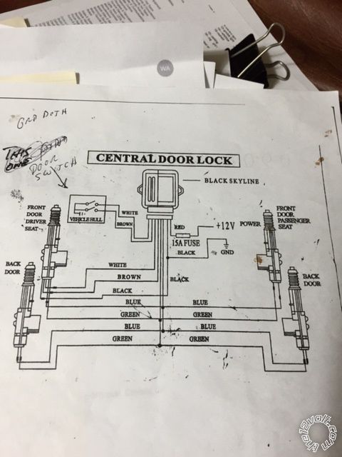
I hope this helps. This is how confusing it gets for me as well.
The yellow isn't connected to anything. Its setting on the steering wheel with the other 7 wires that are not going to be hooked up. The white h1/10 does work. the 2 3 4 13 14 18 don't do anything when the key fob is pushed.
Does this help?
Thank You,
WAYNES WORLD
waynes world
davep. 
Gold - Posts: 641
Gold spacespace
Joined: May 27, 2011
Location: California, United States
Posted: January 25, 2015 at 12:04 AM / IP Logged  
Now we're getting somewhere.
violet and violet/ black to ground.
grn/blk to white at door switch
blu/blk to brown at door switch.
If lock and unlock are "backwards", reverse the second two connections.
wanes world 
Member - Posts: 18
Member spacespace
Joined: January 17, 2015
Location: Illinois, United States
Posted: January 25, 2015 at 12:18 AM / IP Logged  
Davep,
I'll give that a try tomorrow.
Which wire goes to the other actuators?
Thank You very Much,
waynes world
davep. 
Gold - Posts: 641
Gold spacespace
Joined: May 27, 2011
Location: California, United States
Posted: January 25, 2015 at 12:26 AM / IP Logged  
Does the door switch lock and unlock both doors?
If so, those connections will work. They will have the 211 doing the same thing electrically that the door switch does. No 211 wiring goes to the actuators.
Wire the actuators and module as shown in the "Central Locking System" diagram.
wanes world 
Member - Posts: 18
Member spacespace
Joined: January 17, 2015
Location: Illinois, United States
Posted: January 25, 2015 at 12:30 AM / IP Logged  
Davep,
I really appreciate your patience in helping me with this issue.
Thank You,
WAYNES WORLD
waynes world
Page of 3

  Printable version Printable version Post ReplyPost New Topic
You cannot post new topics in this forum
You cannot reply to topics in this forum
You cannot delete your posts in this forum
You cannot edit your posts in this forum
You cannot create polls in this forum
You cannot vote in polls in this forum

  •  
Search the12volt.com
Follow the12volt.com Follow the12volt.com on Facebook
Tuesday, April 16, 2024 • Copyright © 1999-2024 the12volt.com, All Rights Reserved Privacy Policy & Use of Cookies
Disclaimer: *All information on this site ( the12volt.com ) is provided "as is" without any warranty of any kind, either expressed or implied, including but not limited to fitness for a particular use. Any user assumes the entire risk as to the accuracy and use of this information. Please verify all wire colors and diagrams before applying any information.

Secured by Sectigo
the12volt.com spacer
Support the12volt.com
Top
the12volt.com spacer