the12volt.com spacer
icon

Fan Switch Relay


Post ReplyPost New Topic
< Prev Topic Next Topic >
timkins 
Member - Posts: 37
Member spacespace
Joined: July 21, 2004
Location: United States
Posted: June 03, 2005 at 8:18 PM / IP Logged  
I just purchased a switch that goes in the intake manifold that automatically goes on when the temp hits a specified degree. I used the relay diagram provided before on this site and know how to put the new switch in the system. My question is: how do I add a manual override switch in the system? That would enable me to turn the fan on/off when I wanted to but also have the protection if I forgot.
Ween 
Platinum - Posts: 1,364
Platinum spacespace
Joined: August 01, 2004
Location: Illinois, United States
Posted: June 03, 2005 at 10:13 PM / IP Logged  

hi,

if the temp switch has two terminals, a spst switch across the terminals will provide a manual override.  if it has one terminal, a spst to that terminal and ground will do the same.

mark

timkins 
Member - Posts: 37
Member spacespace
Joined: July 21, 2004
Location: United States
Posted: June 23, 2005 at 7:14 AM / IP Logged  
OK, I must be really thick or just plain stoopid. On a previous post I asked for a diagram on installing a relay to power a one wire thermostatic switch with a manual on/off overide switch. The original diagram did not show the terminals to be used in hooking up the relay. Can someone show a diagram with the terminals used to accomplish this installation.
thepencil 
Gold - Posts: 1,526
Gold spacespace
Joined: December 16, 2002
Location: Canada
Posted: June 23, 2005 at 10:30 AM / IP Logged  
relay diagram.
Pin 85 - will be the manual switch in which you will have ground only when you need to use it.
Pin 86 & 30 - will be constant +12V
Pin 87a - will go to the device that you want to power up all the time. Keep in mind that pin 87a and pin 30 will have continuity when the relay is not energized.
That being said, this means when you want to manually over ride the system all you will need to do is switch the pin 85 to ground which will energized the relay.   Than the contact between pin 87a and and pin 30 will become open shutting the device off manually.
Pin 87 will not be used.
I hope this is what you are looking to achieve.
Be careful whose advice you buy, but be patient with those who supply it.Fan Switch Relay -- posted image.
timkins 
Member - Posts: 37
Member spacespace
Joined: July 21, 2004
Location: United States
Posted: June 23, 2005 at 1:07 PM / IP Logged  

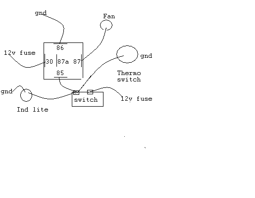
This is how it is currently wired, will it work???

Fan Switch Relay -- posted image.

Hoptup32 
Copper - Posts: 87
Copper spacespace
Joined: December 25, 2004
Location: United States
Posted: June 24, 2005 at 3:18 PM / IP Logged  
Is this for an electric radiator fan or some other type of 12v fan, like for an AC/Heater unit?
timkins 
Member - Posts: 37
Member spacespace
Joined: July 21, 2004
Location: United States
Posted: June 24, 2005 at 3:34 PM / IP Logged  
This is for a 12v fan attached to the radiator for cooling.  I tried the instructions from "thepencil" and it did not work, so I went back to the diagram I posted, only this time I left off the wire from the thermostatic switch because if it closed it would go to ground and short  the whole thing out. So I am completely lost as to how to hook the thermostatic switch up and retain the manual on/off switch.
Hoptup32 
Copper - Posts: 87
Copper spacespace
Joined: December 25, 2004
Location: United States
Posted: June 24, 2005 at 8:27 PM / IP Logged  

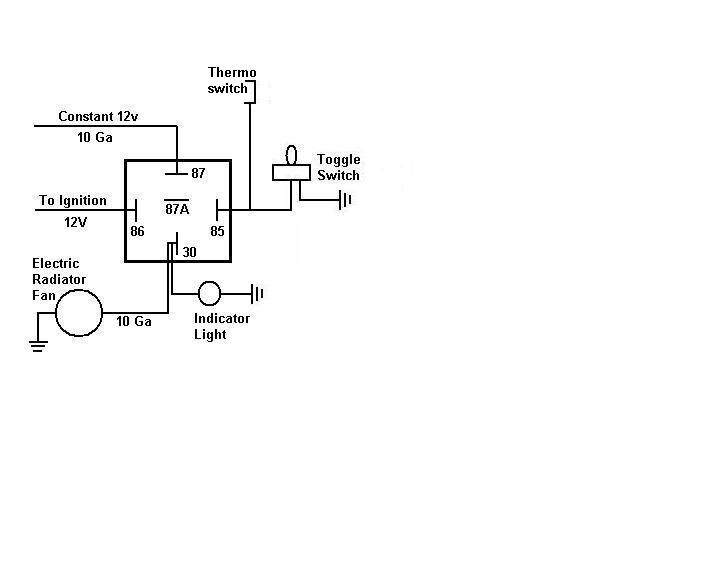
The one wire thermo switch goes to ground as the engine temp rises.  The way you have it wired, the fan will only work when the manual switch is used.  The manual override switch needs to be a ground source.  The diagram I have attached shows you one way to setup the wiring, the manual switch can be used before the thermo switch would come on, but once the therno switch goes to ground, turning the manual switch off will not stop the fan operation since the thermo switch will be completing the circuit. 

I recommend controlling the fan relay with a 12V ignition source, so that the fan will cut off when the ignition is turned off, otherwise, the fan will run until the temp cools and the therno switch deactivates the power.  Of course, if you want the fan to run after the ignition switch is off, then use a constant 12V source to relay terminal 86, but your battery will be providing all of the power once the engine is off, and electric fans pull a lot of amps, so your battery would need to be really healthy to repeat that scenario everytime. Personally, I wouldn't wire it to run after the ignition is off. 

Also, if you have air conditioning, the electric fan should be wired to run whenever the ac is turned on, regardless of the engine temp.  Its needed to move air across the ac condensor to cool the refrigerant and to keep the internal pressure down. This would require a second relay in addition to the one shown here. 

Fan Switch Relay -- posted image.


Sorry, you can NOT post a reply.
This topic is closed.

  Printable version Printable version Post ReplyPost New Topic
You cannot post new topics in this forum
You cannot reply to topics in this forum
You cannot delete your posts in this forum
You cannot edit your posts in this forum
You cannot create polls in this forum
You cannot vote in polls in this forum

  •  
Search the12volt.com
Follow the12volt.com Follow the12volt.com on Facebook
Tuesday, April 16, 2024 • Copyright © 1999-2024 the12volt.com, All Rights Reserved Privacy Policy & Use of Cookies
Disclaimer: *All information on this site ( the12volt.com ) is provided "as is" without any warranty of any kind, either expressed or implied, including but not limited to fitness for a particular use. Any user assumes the entire risk as to the accuracy and use of this information. Please verify all wire colors and diagrams before applying any information.

Secured by Sectigo
the12volt.com spacer
Support the12volt.com
Top
the12volt.com spacer