the12volt.com spacer
icon

best way to reverse polarity on solenoid


Post ReplyPost New Topic
< Prev Topic Next Topic >
haemphyst 
Platinum - Posts: 5,054
Platinum spaceThis member has been recognized as an authority in Electrical Theory. Click here for more info.spaceThis member has been recognized as an authority in Mobile Audio and Video. Click here for more info.spacespace
Joined: January 19, 2003
Location: Michigan, Bouvet Island
Posted: April 21, 2009 at 2:40 PM / IP Logged  
i am an idiot wrote:
I think he meant to say i only showed you the low current control for your solenoid.  That is only the DPDT switch. 
Which are what is connected to the load... The high-current terminals...
Wait... I am TOTALLY lost, now... I know it's not hard to confuse me sometimes, but what are you showing?
It all reminds me of something that Molière once said to Guy de Maupassant at a café in Vienna: "That's nice. You should write it down."
fisherangel7 
Member - Posts: 21
Member spacespace
Joined: April 20, 2009
Posted: April 21, 2009 at 3:52 PM / IP Logged  

HI "Iamanidiot",  Do you have a "Complete" schematic for this. I am looking for the lowest parts count and hopefully 1 or PULSE activation (from a momentary switch perhaps) .   Again we are locked into a single coil latching solenoid @12 volts on control side.     My understanding of the DPDT (double pole double throw) switchs is that they connect either A and B terminals or they connect C and D ,  (thus you can get two separate circuits (Either AB or CD but not both at same time).    If you tie A and C together  you get a SPDT switch..  By using this as SPDT you can apply + for example to two different places (but only one at a time).   

None of this actually reverses BOTH NEG AND POS polarity (both neg and pos must be reversed to activate the solenoid from one position to the other since it is a single coil type. )

Wonder if what is really needed is a   4P2T switch with an at rest position so that when control power is dropped it doesn't go back to the other position? (or use 2 DPDT's ganged together, higher parts count again). 

Guess we were hoping that someone had already figured a way to get it to one pulse with some neat gimmick method with low parts counts..  one guy mentioned using diodes to reverse the polarity?  any info?

KPierson 
Platinum - Posts: 3,527
Platinum spaceThis member consistently provides reliable informationspace
Joined: April 14, 2005
Location: Ohio, United States
Posted: April 21, 2009 at 6:22 PM / IP Logged  

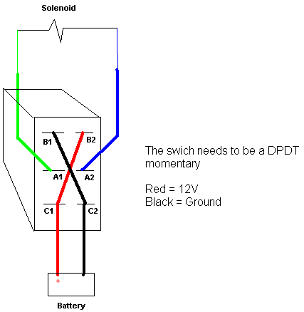
I took the liberty of completing the drawing - I am an idiot I hope you don't mind me adding to your initial drawing;

best way to reverse polarity on solenoid - Page 2 -- posted image.

Kevin Pierson
KPierson 
Platinum - Posts: 3,527
Platinum spaceThis member consistently provides reliable informationspace
Joined: April 14, 2005
Location: Ohio, United States
Posted: April 21, 2009 at 6:23 PM / IP Logged  
I appologize for my mistake, I really should have added a fuse in there somewhere (as close to the battery as possible).
Kevin Pierson
i am an idiot 
Platinum - Posts: 13,667
Platinum spaceThis member consistently provides reliable informationspace
Joined: September 21, 2006
Location: Louisiana, United States
Posted: April 21, 2009 at 6:45 PM / IP Logged  
A very small fuse at that.  5 amps should be fine.    Thanks for finishing the drawing.  I hate details.  Maybe I will draw the high current section of the solenoid tonight.  That may take a larger fuse.
i am an idiot 
Platinum - Posts: 13,667
Platinum spaceThis member consistently provides reliable informationspace
Joined: September 21, 2006
Location: Louisiana, United States
Posted: April 21, 2009 at 6:54 PM / IP Logged  
Did you purchase the switch yet?   It will clear up a lot, when you get the switch.   I am fully aware of how your solenoid operates.  The above switch and wiring WILL reverse the polarity to connect the common pole of the relay to the NC pole or the NO connection.  If of course the contacts are labeled NO and NC.  Since it is a latching relay, they may not be labeled that way.
fisherangel7 
Member - Posts: 21
Member spacespace
Joined: April 20, 2009
Posted: April 21, 2009 at 7:34 PM / IP Logged  

Thanks.. I am getting the idea..  THANKS!   Let me add an additional twist to the equation for more fun !!

Ideally we would like to use our microcontroller to use only ONE port to send one pulse the  large single coil latching solenoid XX (100amp72volt) to make it go from position A to position B.      Of course this is very hard to do with existing microcontrollers.  So we then fall back to using intermediate relays.. BUT we would like to have no power whatsoever on anything once the big XX solenoid latches up (either A or B position).   Do you have a way to eliminate all power on control side .. 

It looks like with the DPDT system you named, it would still be feeding current to the big XX solenoid which because it is a latching big solenoid doesn't need control power any more. 

  Any advice is gratefully appreciated.  THanks.  

fisherangel7 
Member - Posts: 21
Member spacespace
Joined: April 20, 2009
Posted: April 21, 2009 at 7:50 PM / IP Logged  

In other words a DPDT relay with a center "rest" position would be nice .. so that no control power flow  except when pulsed from microcontroller (MCU)  (its a 5 volt pulse which we can very easily with a mosfet boost up in voltage and amps from micrrocontroller). 

Failing a one pulse system ( using no control power except when pulse come thru), a 2 wire system would be next best (uses 2 ports (wires)  from MCU but probably only 1 would pulse at any one time).  

fisherangel7 
Member - Posts: 21
Member spacespace
Joined: April 20, 2009
Posted: April 21, 2009 at 8:07 PM / IP Logged  

Just so we all know.. the insde the relay schematic for a single coil DPDT relay is below.   1 and 8 are the control power .   3 and 6 are the +  and - for the main battery supply respectively .   Connect 2 motor leads to 2 and 7 ;  and  connect with external wires terminal 2 to 5  and also  connect 4 to 7;  that gives polarity reversing when relay is actuated.  

  The at rest position is shown;  so motor terminal 2 is + and motor Terminal at 7  is  - .    

When the power at 1,8 is reversed. the contacts are then 3 to 4 which is also connect to 7 making the motor lead opposite of what it was (now it becomes +),  same for other side  6 connects to 5 which is also connected to 2 (making it -) which is opposite polarity of previous.

Thanks to Iamanidiot's comments. 

best way to reverse polarity on solenoid - Page 2 -- posted image.

i am an idiot 
Platinum - Posts: 13,667
Platinum spaceThis member consistently provides reliable informationspace
Joined: September 21, 2006
Location: Louisiana, United States
Posted: April 21, 2009 at 8:23 PM / IP Logged  

A momentary switch just applies voltage momentarily.  This means when you release the switch, it goes to the off position.   This new twist you bring into the equation would have really been helpful in the initial post.  Since you are not intending on using a manually operated switch, I have wasted tons of tme trying to help you understand something that is totally useless.

Yes I do know how to eliminate all power drain on the control side.  There is none.

Page of 5

  Printable version Printable version Post ReplyPost New Topic
You cannot post new topics in this forum
You cannot reply to topics in this forum
You cannot delete your posts in this forum
You cannot edit your posts in this forum
You cannot create polls in this forum
You cannot vote in polls in this forum

  •  
Search the12volt.com
Follow the12volt.com Follow the12volt.com on Facebook
Saturday, April 20, 2024 • Copyright © 1999-2024 the12volt.com, All Rights Reserved Privacy Policy & Use of Cookies
Disclaimer: *All information on this site ( the12volt.com ) is provided "as is" without any warranty of any kind, either expressed or implied, including but not limited to fitness for a particular use. Any user assumes the entire risk as to the accuracy and use of this information. Please verify all wire colors and diagrams before applying any information.

Secured by Sectigo
the12volt.com spacer
Support the12volt.com
Top
the12volt.com spacer