the12volt.com spacer
icon

viper 5701 with fortin evo all


Post ReplyPost New Topic
< Prev Topic Next Topic >
tedmond 
Gold - Posts: 4,610
Gold spaceThis member has been recognized as an authority in Mobile Security and Convenience. Click here for more info.spacespace
Joined: January 06, 2007
Location: Ontario, Canada
Posted: December 15, 2011 at 1:37 PM / IP Logged  
use diodes on the lock/unlock wire to the db-all. diode band towards viper.
the viper uses flip polarity on the locks if i remember unless they changed it.
Ted
2nd Year Tier 1 Medical School
Still installing as a hobby...pays for groceries
Compustar Expert
theghostman01 
Member - Posts: 27
Member spacespace
Joined: December 13, 2011
Location: Quebec, Canada
Posted: December 15, 2011 at 1:51 PM / IP Logged  
Sorry about that maybe iv make a mistake but the db-all is not for the same car that the car with power lock/unlock problem
The car with lock wire problem is a toyota corrola 2000 with a prostart ct-5400 tw remote-start with negative wire for the unlock,lock .
My problem is because on the car, the wire for the lock/unlock is also negative then i dont know how to connect these 2 wires.
Maybe i should use 2 relay one for each wire. 1 relay lock, 1 unlock
Is it the simply way?
And sorry about all the incorrect words normally i speak in French.
ThE GhOsTmAn01
theghostman01 
Member - Posts: 27
Member spacespace
Joined: December 13, 2011
Location: Quebec, Canada
Posted: December 24, 2011 at 1:24 PM / IP Logged  

Hi again all, thank you for all your awnser and HAPPY CHRISTMAS !!

First of all ill expose my problem ...

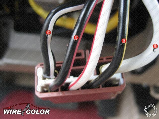
The viper 5701 that i bought is refurbished , that mean that the module dont come with any instructions. BUT i have find on xpresskit.com my wiring diagram for my car.

ignition : BLACK / YELLOW

12 volts:white

starter:BLACK/ white

acc 1:BLACK/ red

acc 2:WHITE/ red

But from installation guide the name of the wires are not the same, ill post all the wiring of the installation guide and if you want to help me to join each of us ill be so happy .viper 5701 with fortin evo all - Page 2 -- posted image.

From the guide on the h3 10-pin connector :

pink           /(+) ignition 1 input/output

red-white / (87)flex relay +12v input (30a fused)

orange     / (+) accessory output

violet        /(+)starter output (car side)

green       /(+)starter input (key side)

red           /ignition 1 +12v input (30a fused)

pink-WHITE/  (30) flex relay output (car side of ign, acc or starter wire)

pink-BLACK/  (87a) flex relay input (keyside of ign,acc or starter wire if needed)

red-black / accessory/starter relay +12v input (30a fused)

This is my ignition harness viper 5701 with fortin evo all - Page 2 -- posted image.

Hope to be help, to help next time too viper 5701 with fortin evo all - Page 2 -- posted image.             viper 5701 with fortin evo all - Page 2 -- posted image. HAPPY CHRISTMAS ALLviper 5701 with fortin evo all - Page 2 -- posted image.

ThE GhOsTmAn01
theghostman01 
Member - Posts: 27
Member spacespace
Joined: December 13, 2011
Location: Quebec, Canada
Posted: December 24, 2011 at 1:37 PM / IP Logged  
theghostman01 wrote:

Forget to tell that i replaced the fortin evo-all by a db-all from expresskit that is d2d compatible !!

And from the sheet of my db-all, i need to connect a ground wire from my remote-start to the chassis but is it the small ground wire from the other connector on the other side of the remote-start? I think this small gauge ground wire is for all the other acc like trunk output,unlock output ....


Hi again all, thank you for all your awnser and HAPPY CHRISTMAS !!

First of all ill expose my problem ...

The viper 5701 that i bought is refurbished , that mean that the module dont come with any instructions. BUT i have find on xpresskit.com my wiring diagram for my car.

ignition : BLACK / YELLOW

12 volts:white

starter:BLACK/ white

acc 1:BLACK/ red

acc 2:WHITE/ red

But from installation guide the name of the wires are not the same, ill post all the wiring of the installation guide and if you want to help me to join each of us ill be so happy .viper 5701 with fortin evo all - Page 2 -- posted image.

From the guide on the h3 10-pin connector :

pink           /(+) ignition 1 input/output

red-white / (87)flex relay +12v input (30a fused)

orange     / (+) accessory output

violet        /(+)starter output (car side)

green       /(+)starter input (key side)

red           /ignition 1 +12v input (30a fused)

pink-WHITE/  (30) flex relay output (car side of ign, acc or starter wire)

pink-BLACK/  (87a) flex relay input (keyside of ign,acc or starter wire if needed)

red-black / accessory/starter relay +12v input (30a fused)

This is my ignition harness viper 5701 with fortin evo all - Page 2 -- posted image.

Hope to be help, to help next time too viper 5701 with fortin evo all - Page 2 -- posted image.             viper 5701 with fortin evo all - Page 2 -- posted image. HAPPY CHRISTMAS ALLviper 5701 with fortin evo all - Page 2 -- posted image.

ThE GhOsTmAn01
theghostman01 
Member - Posts: 27
Member spacespace
Joined: December 13, 2011
Location: Quebec, Canada
Posted: December 24, 2011 at 1:41 PM / IP Logged  

Hi again all, thank you for all your awnser and HAPPY CHRISTMAS !!

First of all ill expose my problem ...

The viper 5701 that i bought is refurbished , that mean that the module dont come with any instructions. BUT i have find on xpresskit.com my wiring diagram for my car.

ignition : BLACK / YELLOW

12 volts:white

starter:BLACK/ white

acc 1:BLACK/ red

acc 2:WHITE/ red

But from installation guide the name of the wires are not the same, this is all the wiring of the installation guide and if you want to help me to join each of us ill be so happy .viper 5701 with fortin evo all - Page 2 -- posted image.

From the guide on the h3 10-pin connector :

pink           /(+) ignition 1 input/output

red-white / (87)flex relay +12v input (30a fused)

orange     / (+) accessory output

violet        /(+)starter output (car side)

green       /(+)starter input (key side)

red           /ignition 1 +12v input (30a fused)

pink-WHITE/  (30) flex relay output (car side of ign, acc or starter wire)

pink-BLACK/  (87a) flex relay input (keyside of ign,acc or starter wire if needed)

red-black / accessory/starter relay +12v input (30a fused)

This is my ignition harness viper 5701 with fortin evo all - Page 2 -- posted image.

Hope to be help, to help next time too viper 5701 with fortin evo all - Page 2 -- posted image.             viper 5701 with fortin evo all - Page 2 -- posted image. HAPPY CHRISTMAS ALLviper 5701 with fortin evo all - Page 2 -- posted image.

Forget to tell that i replaced the fortin evo-all by a db-all from expresskit that is d2d compatible !!

And from the sheet of my db-all, i need to connect a ground wire from my remote-start to the chassis but is it the small ground wire from the other connector on the other side of the remote-start? I think this small gauge ground wire is for all the other acc like trunk output,unlock output ....

ThE GhOsTmAn01
theghostman01 
Member - Posts: 27
Member spacespace
Joined: December 13, 2011
Location: Quebec, Canada
Posted: December 26, 2011 at 8:25 PM / IP Logged  
Someone please !!
ThE GhOsTmAn01
offroadzj 
Gold - Posts: 2,043
Gold spaceThis member has made a donation to the12volt.com. Click here for more info.spaceThis member has been recognized as an authority in Mobile Security and Convenience. Click here for more info.spacespace
Joined: June 03, 2005
Location: New York, United States
Posted: December 26, 2011 at 8:47 PM / IP Logged  
The red, RED / white, and RED / black are all going to connect to your 12v constant (white). Pink will go to your ignition (BLACK / YELLOW). Orange will go to your accessory 1 (BLACK/ red). Pink/White will go to your accessory 2 (WHITE/ red) **You will need to change the programming option for the flex relay to 2nd accessory!!. The Violet will go to your starter wire (BLACK/ white). The pink/black and green are not used (unless you want the starter kill option in which case the BLACK/ white wire will be cut; purple goes to the car side of the wire, green goes to the switch side of the wire). The ground off the DB-All and the ground off the unit all need to go to a good low chassis ground.
As far as the lock/unlock problem, you can try using 2 relays to get a stronger ground signal. Connect the relays as follows:
30 to chassis ground (both relays)
87 to unlock / lock wire on car (lock on one relay, unlock on the other)
87a no connection
86 12v constant (both relays)
85 lock / unlock output from Viper (lock on one relay, unlock on the other)
To be 100% honest, if you are not 100% confident with car electrical, I would bring it to a professional. You can cause a lot of damage if you make one wrong connection.
Kenny
Owner / Technician
KKD Garage LLC
Albany, NY 12205
smokeman1 
Platinum - Posts: 1,588
Platinum spaceThis member has made a donation to the12volt.com. Click here for more info.spaceThis member has been recognized as an authority in Mobile Security and Convenience. Click here for more info.spacespace
Joined: September 14, 2009
Location: Wisconsin, United States
Posted: December 26, 2011 at 8:54 PM / IP Logged  

If you are not using a DMM to test and verify each wire before making any of your connections you are heading for frustration.  In the downloads section of this site is the install manual for the 5701.  In it there is a section for finding and testing for the wires you need.  DON'T just go by a wire guide. It may be, or your car might be different.  TEST and VERIFY.

Door locks are listed as type B.  Lock and unlock wires should connect to the vehicle wiring without the need for relays.

http://www.bulldogsecurity.com/bdnew/vehiclewiringdiagrams.asp

When all else fails, Read the Instructions
Support the12volt.com Make a Donation
offroadzj 
Gold - Posts: 2,043
Gold spaceThis member has made a donation to the12volt.com. Click here for more info.spaceThis member has been recognized as an authority in Mobile Security and Convenience. Click here for more info.spacespace
Joined: June 03, 2005
Location: New York, United States
Posted: December 26, 2011 at 8:59 PM / IP Logged  
exactly what he said. I was assuming you were using a DMM... if not, you are headed for failure. I would recheck your lock wires as they should not require the relays... but if you are 100% sure they are correct and still not working, then using the relay may work.
Kenny
Owner / Technician
KKD Garage LLC
Albany, NY 12205
theghostman01 
Member - Posts: 27
Member spacespace
Joined: December 13, 2011
Location: Quebec, Canada
Posted: December 27, 2011 at 9:58 AM / IP Logged  
Thamk you so much guy ! Yes iam using a tester but only a pencil light for 12v at this time.But its not the first time i install a remote start on my car but the in the past the name of the conection was more clear (for me).
And for the lock unlock problem it not for this Honda Accord 2003,on this car i am using the d2d option but on the other car Toyota Corrola 2000 the wire is negative and the signal from the lock unlock is negative too.
Wow guy i just see that i am not using the good installation guide ...
the good one is the first one in the download section .I was using the 5701 guide but the new version ! In this verion the connection is NOT explaned instead of the other guide.
Thank you again guy.
ThE GhOsTmAn01
Page of 6

  Printable version Printable version Post ReplyPost New Topic
You cannot post new topics in this forum
You cannot reply to topics in this forum
You cannot delete your posts in this forum
You cannot edit your posts in this forum
You cannot create polls in this forum
You cannot vote in polls in this forum

  •  
Search the12volt.com
Follow the12volt.com Follow the12volt.com on Facebook
Saturday, April 20, 2024 • Copyright © 1999-2024 the12volt.com, All Rights Reserved Privacy Policy & Use of Cookies
Disclaimer: *All information on this site ( the12volt.com ) is provided "as is" without any warranty of any kind, either expressed or implied, including but not limited to fitness for a particular use. Any user assumes the entire risk as to the accuracy and use of this information. Please verify all wire colors and diagrams before applying any information.

Secured by Sectigo
the12volt.com spacer
Support the12volt.com
Top
the12volt.com spacer