the12volt.com spacer
icon

2010 Toyota Tacoma Remote Start Pictorial


Post ReplyPost New Topic
< Prev Topic Next Topic >
cruzs2013sr5 
Member - Posts: 10
Member spacespace
Joined: March 24, 2013
Location: Texas, United States
Posted: May 04, 2013 at 2:58 PM / IP Logged  
cruzs2013sr5 wrote:
Hello everyone. I just signed up to this forum. WOW! Lots of information. I was just wondering if anyone knew if this thread, (wiring) how-to was at all similar to the 2013 Tacoma. I was just wondering if it was different. I was thinking of buying the Pyton 574 with remote start for my truck. Thanks.
Anyone?
Cruzer
kreg357 
Platinum - Posts: 7,783
Platinum spaceThis member has made a donation to the12volt.com. Click here for more info.spaceThis member has been recognized as an authority in Electrical Theory. Click here for more info.spaceThis member has been recognized as an authority in Mobile Security and Convenience. Click here for more info.spacespace
Joined: January 30, 2009
Location: Pennsylvania, United States
Posted: May 04, 2013 at 4:07 PM / IP Logged  

According to Bulldog Security, they are the same.  Here is a link to their wire guide listing :

http://diagrams.marktoonen.nl/printlist.aspx?MakeID=2&ModelID=20135

Check your ignition key for the "G" stamp.

Soldering is fun!
cruzs2013sr5 
Member - Posts: 10
Member spacespace
Joined: March 24, 2013
Location: Texas, United States
Posted: May 04, 2013 at 6:30 PM / IP Logged  
Thank you.
Cruzer
tonanzith 
Gold - Posts: 593
Gold spaceThis member consistently provides reliable informationspace
Joined: July 18, 2008
Location: Washington, United States
Posted: May 04, 2013 at 10:53 PM / IP Logged  
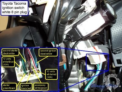
12 Volts     WHITE/ red (30A)     +     ignition switch, white 8 pin plug, pin 5
Second 12 Volts     WHITE/ blue (50A)     +     ignition switch, white 8 pin plug, pin 4
Starter     GREEN/ black     +     ignition switch, white 8 pin plug, pin 7
Second Starter     BLACK/ white     +     ignition switch, white 8 pin plug, pin 3
Ignition     BLACK/ red     +     ignition switch, white 8 pin plug, pin 6
Second Ignition     blue / YELLOW     +     ignition switch, white 8 pin plug, pin 1
Third Ignition     N/A
Accessory     WHITE/ green     +     ignition switch, white 8 pin plug, pin 2
Second Accessory     N/A
Third Accessory     N/A
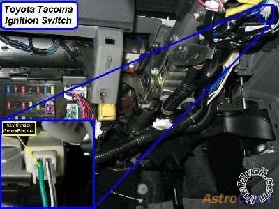
Keysense     GREEN/ black     -     ignition key switch, white 2 pin plug, pin 1
Data Bus     pink/green (RX), lt. GREEN/ red (TX)     data     Transponder Key Amplifier, black 7 pin plug, pins 4 and 5
Can Bus High     yellow/black     data     data link connector, white 16 pin plug, pin 6
Can Bus Low     blue/white     data     data link connector, white 16 pin plug, pin 14
Can Bus Sw     N/A
Power Lock     blue/white     -     driver kick, gray 10 pin plug, pin 6
Power Unlock     gray     -     driver kick, gray 10 pin plug, pin 7
Lock Motor     blue/red     5 wire     driver kick, white 12 pin plug, pin 10 or black 8 pin plug, pin 6
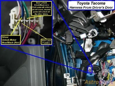
Driver Unlock Motor     blue/black     5 wire     driver kick, gray 10 pin plug, pin 9
Passenger Unlock Motor     blue/black     5 wire     dash fuse box, rear, white 24 pin plug (1H), pin 5
Parking Lights (-)     green     -     headlight switch, white 20 pin plug, pin 18
Parking Lights (+)     green     +     dash fuse box, white 13 pin plug (1D), pin 10
Hazards     RED / white     -     hazard switch, white 14 pin plug, pin 9
Turn Signal (Left)     yellow (F); yellow (R) (common on models w/o DRL)     +     dash fuse box, wht 11 pin plg (1B), pin 7; wht 13 pin plg (1D), pin 11
Turn Signal (Right)     lt. blu (F); blu/wht (R)(common on models w/o DRL)     +     dash fuse box, wht 11 pin plg (1B), pin 5; wht 13 pin plg (1D), pin 4
Headlight     pink     -     headlight switch, white 20 pin plug, pin 20
AutoLights     N/A
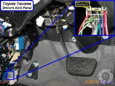
Reverse Light     red     +     driver kick, gray 12 pin plug, pin 1
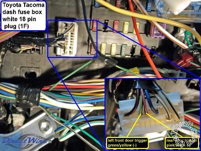
Left Front Door Trigger     GREEN/ YELLOW     -     dash fuse box, white 18 pin plug (1F), pin 7
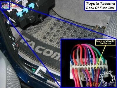
Right Front Door Trigger     RED / black     -     dash fuse box, rear, white 22 pin plug (1I), pin 8
Left Rear Door Trigger     pink/black     -     dash fuse box, white 18 pin plug (1F), pin 6
Right Rear Door Trigger     same as left rear door trigger
Remote Start, Security, Keyless Entry, Accessories (Continued)
Item     Wire Color     Polarity     Wire Location
Dome Supervision     blue     -     dash fuse box, black 13 pin plug (1E), pin 9
Trunk/Hatch Pin     N/A
Rear Glass Pin     N/A
Hood Pin     N/A
Trunk/Hatch Release     N/A
Trunk Release Motor     N/A
Fuel Door Release     N/A
Power Sliding Door (Left)     N/A
Power Sliding Door (Right)     N/A
Factory Alarm Arm     purple (driver door key lock)     -     driver kick, gray 10 pin plug, pin 4
Factory Alarm Disarm     GREEN/ black (driver door key unlock)     double -     driver kick, gray 10 pin plug, pin 8
Disarm No Unlock     use keysense
Trunk Alarm Shunt     N/A
Tachometer     BLACK/ white     ac     data link connector, white 16 pin plug, pin 9
Wait to Start     N/A
Neutral Safety     N/A
Clutch Pedal     BLACK / YELLOW     +     clutch switch, black 2 pin plug, pin 2
Fuel Pump     BLACK/ red     +     driver kick, white 18 pin plug, pin 8
Rear Defroster     N/A
Mirror Defroster     N/A
Left Front Heated Seat     purple     + resistor     driver kick, white 18 pin plug, pin 4
Right Front Heated Seat     purple     + resistor     passenger kick, gray 11 pin plug, pin 2
Speed Sense     PURPLE / white     ac     dr kick junc box, wh 20 pin plg, pin 10, or radio, wh 28 pin plg, pin 17
Brake Wire     blue     +     dash fuse box, white 13 pin plug (1D), pin 13
Parking Brake     GREEN/ YELLOW     -     dash fuse box, white 18 pin plug (1C), pin 5
Horn Trigger     GREEN/ red     -     dash fuse box, white 18 pin plug (1C), pin 10
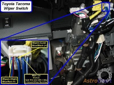
Wipers     blue/black (low), blue/red (high), blue (ignition)     +     wiper switch, white 10 pin plug, pins 3, 4, and 2
Left Front Window (Up/Down)     blue - blue/black     A     power window master switch, white 18 pin plug, pins 10 - 12, or 3 - 4
Right Front Window (Up/Down)     blue / YELLOW - black     A     driver kick, white 12 pin plug, pins 2 and 3
Left Rear Window (Up/Down)     GREEN / WHITE - GREEN/ red     A     driver kick, white 7 pin plug, pins 6 and 5
Right Rear Window (Up/Down)     GREEN/ black - green     A     driver kick, black 8 pin plug, pins 7 and 3
2010 Toyota Tacoma Remote Start Pictorial - Page 2 -- posted image.
Gary Sather
joeschmuck 
Member - Posts: 21
Member spacespace
Joined: December 30, 2012
Location: Virginia, United States
Posted: July 28, 2013 at 9:51 AM / IP Logged  
@tonanzith
Do you have higher quality pictures, the ones posted are difficult to read (letters are all blocky). These are really nice to have for certain!
joeschmuck 
Member - Posts: 21
Member spacespace
Joined: December 30, 2012
Location: Virginia, United States
Posted: August 03, 2013 at 10:33 AM / IP Logged  
Deleted.
tarline 
Member - Posts: 7
Member spacespace
Joined: June 22, 2003
Location: United States
Posted: November 10, 2013 at 9:54 AM / IP Logged  
Hello, I'm also new and I'm really glad to find so much info. I'm installing a Samito Electronics HT800 with an Optimax PKALL data module (Bypass)in my 2012 tacoma crew auto, 4x4, . I've run into a few wiring snags, many that have been solved with the pictorials shown. The text on the pics is really hard to read, so any help there would be appreciated. On the PKALL it shows the two wires going to the ECM as "data 1 and data 2" not as txt or rxt. is there a difference? There is one other wire that should be connected to "(-) while running". I have no idea where that should be.
On the alarm/remote start there is one wire that says to connect to oil pressure or ammeter. I can only guess that is to show the remote start that the engine is running. Most of the forums show a connection to the tach. Is that the same? I'm only over my head by a little bit. If I can solve the above, I think I'm home free..
Thanks for any and all help
joeschmuck 
Member - Posts: 21
Member spacespace
Joined: December 30, 2012
Location: Virginia, United States
Posted: November 10, 2013 at 1:55 PM / IP Logged  
For the PKALL, the PURPLE / White wire is the RX (Data In) and connects to the pink/green (RX) line. The Yellow/Black TX (Data Out) connects to the lt. GREEN/ red (TX) line.
The Blue/White (-) While Running line will connect to a (-) Status Output line from your alarm/starter electronics. I do not have the manual for your selected model so I cannot tell you which pin it would be.
When I installed my Python remote, I used about a third of the wires and removed the rest from the connectors as they were not needed for my installation. I did however save those wires in case I need to use one in the future. I did the same to the PKALL. It just cleaned up the installation.
Welcome to the forums and good luck.
tarline 
Member - Posts: 7
Member spacespace
Joined: June 22, 2003
Location: United States
Posted: November 11, 2013 at 7:13 AM / IP Logged  
2010 Toyota Tacoma Remote Start Pictorial - Page 2 -- posted image.
Maybe this diagram will help..
Thanks
tarline 
Member - Posts: 7
Member spacespace
Joined: June 22, 2003
Location: United States
Posted: November 11, 2013 at 7:22 AM / IP Logged  
2010 Toyota Tacoma Remote Start Pictorial - Page 2 -- posted image.
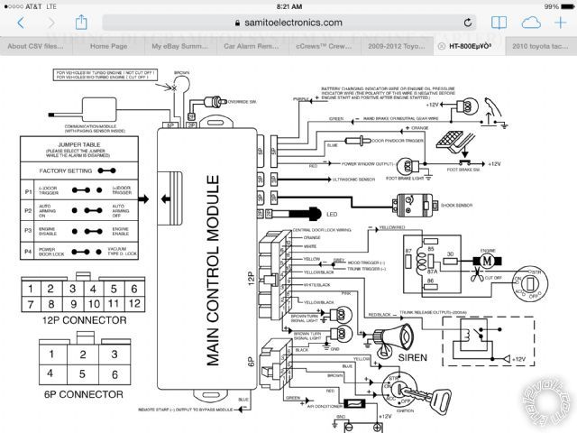
Trying to make it more readable
Page of 4

  Printable version Printable version Post ReplyPost New Topic
You cannot post new topics in this forum
You cannot reply to topics in this forum
You cannot delete your posts in this forum
You cannot edit your posts in this forum
You cannot create polls in this forum
You cannot vote in polls in this forum

  •  
Search the12volt.com
Follow the12volt.com Follow the12volt.com on Facebook
Wednesday, April 17, 2024 • Copyright © 1999-2024 the12volt.com, All Rights Reserved Privacy Policy & Use of Cookies
Disclaimer: *All information on this site ( the12volt.com ) is provided "as is" without any warranty of any kind, either expressed or implied, including but not limited to fitness for a particular use. Any user assumes the entire risk as to the accuracy and use of this information. Please verify all wire colors and diagrams before applying any information.

Secured by Sectigo
the12volt.com spacer
Support the12volt.com
Top
the12volt.com spacer