the12volt.com spacer
icon

relay with timer and thermistor


Post ReplyPost New Topic
< Prev Topic Next Topic >
toyotaguy 
Member - Posts: 22
Member spacespace
Joined: July 06, 2013
Posted: July 16, 2013 at 7:08 PM / IP Logged Link to Post Post Reply Quote toyotaguy
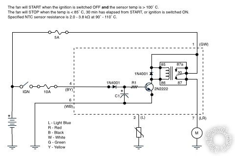
I haven't figured out for certain the values of a couple damaged components in an old fan controller so I thought I'd try designing a replacement board. I've read a metric butt-ton of threads here and on other sites and "think" I have a reasonable start on an analog design. There are lots of delay-off relay designs but they all appear to also apply power while the ignition is on.
The circuit controls an auxiliary fan to cool the carburetor once the engine is switched off. The fan will only run when the ignition is OFF and the NTC thermistor resistance is below a given threshold. Once the fan starts, it will run until the thermistor resistance rises above a threshold, 30 minutes elapses, or the ignition is switched back ON.
1. Is my design reasonable or is there a better approach?
2. When designing the delay-off components, is there a preferred method of choosing values for R1 and C1? In other words, is a lower-value resistor and higher-value capacitor preferred, the other way around, or somewhere in between? There are numerous combinations for creating a 30-minute delay.
3. I'm stuck on how to incorporate the NTC thermistor into the circuit.
Thanks for any feedback.
relay with timer and thermistor -- posted image.
oldspark 
Gold - Posts: 4,913
Gold spacespace
Joined: November 03, 2008
Location: Australia
Posted: July 17, 2013 at 5:21 AM / IP Logged Link to Post Post Reply Quote oldspark
That circuit will turn on as soon as IGN is turned on. More "logic" is needed.
However I think a 30 minute delay using a mere RC and transistor will be difficult to achieve.
IMO the solution lies with a PICAXE (eg, the 08M2) which can do all the logic and timing. Otherwise timer chips and whatever logic is needed.
If it wasn't for the timed limit I'd suggest thermal switch and an IGN triggered SPDT relay where 87a supplies +12V to the fan which is grounded thru a NO (Normally Open) temp switch which is capable of carrying the fan current. Radiator cooling fan switches may be suitable if ranges around 90C are suitable.
Otherwise 87a can power another relay coil which is grounded thru a suitable lower current temp switch, and that relay's 87 can power the fan.
toyotaguy 
Member - Posts: 22
Member spacespace
Joined: July 06, 2013
Posted: July 18, 2013 at 7:19 PM / IP Logged Link to Post Post Reply Quote toyotaguy
Argh. Thanks.
toyotaguy 
Member - Posts: 22
Member spacespace
Joined: July 06, 2013
Posted: July 23, 2013 at 9:11 PM / IP Logged Link to Post Post Reply Quote toyotaguy
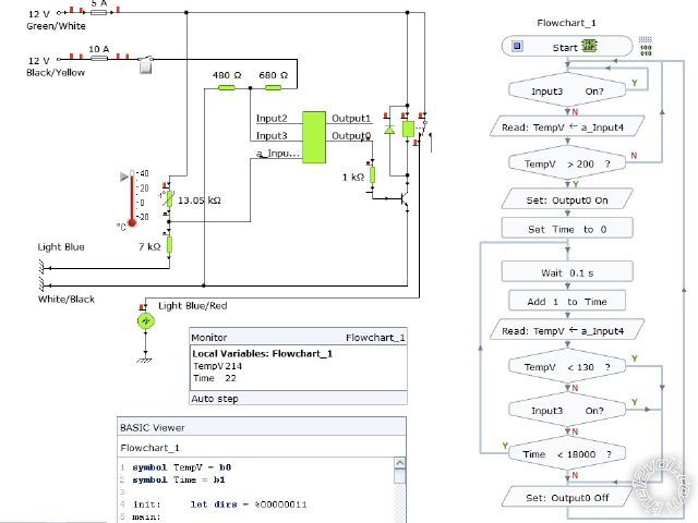
I read about the PICAXE, downloaded the Yenka application and worked on a flowchart and circuit. The thermistor is incorrect, but I'm not sure how to represent the remote sensor using this app. Also there is no voltage regulator in the object library so I just put two resistors in series to give the PICAXE its voltage. The thermistor values are arbitrary and only represent high and low values for the relay's sake. Am I even on the right track? Would you recommend a different application like Fritzing, EAGLE, or something else?
relay with timer and thermistor -- posted image.
oldspark 
Gold - Posts: 4,913
Gold spacespace
Joined: November 03, 2008
Location: Australia
Posted: July 23, 2013 at 9:51 PM / IP Logged Link to Post Post Reply Quote oldspark
I'd worry more about programming etc than the need for a nice drawing.
Start with how you'd read the thermistor values.
And how you'd power the thermister (ie, from the PIC's 5V) else sample the vehicle voltage.
Circuit-wise, use any 3-terminal device for the 7805 else mark the resistors 7805 etc to avoid confusion.
And use proper supply notation - not "input" etc for +5V & 0V/GND.    
And don't forget the programming resistors.
toyotaguy 
Member - Posts: 22
Member spacespace
Joined: July 06, 2013
Posted: February 08, 2014 at 5:23 PM / IP Logged Link to Post Post Reply Quote toyotaguy
My project was temporarily overtaken by events, namely two jobs and a family. However, I'd like to get back to it while I have some time to catch my breath. Last Christmas I ordered a PICAXE for myself and an Arduino for my son and we've spent the last few months experimenting. Quite fun. Thanks for turning me on to the PICAXE.
I redrew the circuit as pictured below but am unsure of incorporating the thermistor. When "cold" (10˚C) the resistance reads 129kΩ. If I use the circuit's 5V supply, what value should I use for R1? (I can replace the sensor with something else if it would be easier though I prefer it to be a single wire sensor, not a three-wire temp probe.)
Does the circuit appear to be correct or have I omitted something (or added something I didn't need)? Is this a "good" design or is there a different approach I should be considering?
relay with timer and thermistor -- posted image.
oldspark 
Gold - Posts: 4,913
Gold spacespace
Joined: November 03, 2008
Location: Australia
Posted: February 09, 2014 at 2:41 AM / IP Logged Link to Post Post Reply Quote oldspark
You only need one 7805 for the 08M2.
Power a 12V relay off the raw 12V supply, hence you don;t need a 5V relay and a regulator that handles its current (a 78L05 is sufficient for the 08M2.
You could use a MOSFET instead of the transistor, but then add a 1M or 100k etc resistor from its Gate (Base) to GND to ensure it turns off.
R1 could be maybe 10k to 100k. It forms a resistive voltage divider with the thermistor.
I'm wondering if that thermistor is too high an impedence for the 08M2 analog input? And if it increases resistance with increasing temperature...
There are other devices like the LM335.
toyotaguy 
Member - Posts: 22
Member spacespace
Joined: July 06, 2013
Posted: February 09, 2014 at 8:16 AM / IP Logged Link to Post Post Reply Quote toyotaguy
I'm not sure I completely follow. There are two 12V sources in the circuit. One is always on to power the PICAXE and the relay and the other is on when the ignition key is in any position other than OFF. Don't I need a regulator for each of the 12V inputs?
oldspark 
Gold - Posts: 4,913
Gold spacespace
Joined: November 03, 2008
Location: Australia
Posted: February 09, 2014 at 8:38 AM / IP Logged Link to Post Post Reply Quote oldspark
Why have the IGN circuit if it's always on?
But assuming you want IGN +12V and something other +12V (maybe a manual switch, ACC +12V etc), then you'd run each +12V source thru a diode (1N400x) to the regulator.
Besides, you can't just wire 2 regulator outputs together...
POST EDIT - Ah - do you mean you have an 08M2 input that senses IGN?
I'd expect this circuit to be IGN powered (so the fan can't flatten the battery etc), but to sense a 12V input you use a resistive divider to reduce the voltage to a max of +5V (or whatever voltage you are using to power the 08M2).
But be careful - a vehicle's 12V can be up to 14.4V and maybe higher. Hence for digital inputs you'd limit the voltage with reverse biased diodes to each rail (0V & 5V). For analog inputs ensure the voltage divider is designed for (say) 20V (ie, IGN is on if the voltage is above 2.5V or 2V etc) thou usually the same diode clamping technique is used (ie, the 2 reverse biased rail diodes).
toyotaguy 
Member - Posts: 22
Member spacespace
Joined: July 06, 2013
Posted: February 09, 2014 at 9:21 AM / IP Logged Link to Post Post Reply Quote toyotaguy
The specifications of the original controller are that the fan starts only when the ignition is switched off and the temp is > 100˚C. The fan will then run until the temp < 85˚C or 30 minutes has elapsed, whichever occurs first. The 08M2 uses the two inputs to control the fan appropriately.
Why would I use a resistive divider rather than a VR and pull-down resistor like the figure? Is there an advantage such as lower cost?
When the fan is not running, there is still 12V powering the 08M2 and 5V through the thermistor. Though the PIC isn't going to drain a car battery, is the thermistor as wired in the circuit a concern? Should I power the thermistor with a PIC pin so I can have it switch off at some time?
Page of 3

  Printable version Printable version Post ReplyPost New Topic
You cannot post new topics in this forum
You cannot reply to topics in this forum
You cannot delete your posts in this forum
You cannot edit your posts in this forum
You cannot create polls in this forum
You cannot vote in polls in this forum

  •  
Search the12volt.com
Follow the12volt.com Follow the12volt.com on Facebook
Friday, April 19, 2024 • Copyright © 1999-2024 the12volt.com, All Rights Reserved Privacy Policy & Use of Cookies
Disclaimer: *All information on this site ( the12volt.com ) is provided "as is" without any warranty of any kind, either expressed or implied, including but not limited to fitness for a particular use. Any user assumes the entire risk as to the accuracy and use of this information. Please verify all wire colors and diagrams before applying any information.

Secured by Sectigo
the12volt.com spacer
Support the12volt.com
Top
the12volt.com spacer