the12volt.com spacer
icon

2005 Saturn Vue Alarm/Remote Start


Post ReplyPost New Topic
< Prev Topic Next Topic >
smalldady01 
Member - Posts: 13
Member spacespace
Joined: October 22, 2013
Location: Quebec, Canada
Posted: October 22, 2013 at 7:20 PM / IP Logged  
Hi I have very some very basic questions, I'm installing an Ultrastart 4296M with IDatalink ADSALCA ADS-AL-CA in a Saturn Vue 2005.
First question, from the bypass module to the remote starter module I have 2 connectors that can be used for the Data, one has a red connector and one has a black connector, what I can figure from the diagram I have is that the black connector is used for 2-way remote starters and red is used for 1-way. is this correct?
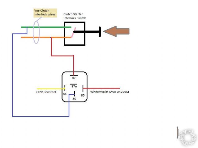
Also from the diagram it shows Lock/Arm (-) input and Unlock/Disarm (-) Input, which goes to the Unlock output (-) and lock (-) output of the remote starter, my question is which wires on the remote starter should this connect to, is it the Output for factory alarm re-arm and Output for factory alarm dis-arm or?
next question, on the remote starter there's a Positive door pin input wire and a negative door pin input. From what I understand only one of these has to be connected depending on what type of door lock you have, from what I can tell mine has positive door trigger. Correct?
My biggest confusion is in making the connections for the doors. I can find the wires in the car no problem but I don't know where they should be connected on the remote starter if someone can guide me using the same terms that are used in the installation manual that would go a long way. Thank you very much
here is the wiring diagram for the remote starter
Connection     Color
OUTPUT TO ACTIVATE START CIRCUIT      Yellow
OUTPUT TO ACTIVATE ACCESSORY/ HEATER CIRCUIT     Green
30A HIGH CURRENT 12VOLT INPUT      Red
30A HIGH CURRENT 12VOLT INPUT     Red
SELECTABLE OUTPUT (DEFAULT SECOND IGNITION)     White
OUTPUT TO ACTIVATE IGNITION CIRCUIT     Blue
      
(+) SIREN/ HORN OUTPUT (-)     Brown
STARTER-KILL/ ANTI-GRIND OUTPUT     Orange
JUMPER SELECTABLE PARK LIGHT OUTPUT (+ OR -)     White
SYSTEM GROUND INPUT     Black
      
NEGATIVE OUTPUT FOR UNLOCK     Green
12+ OUTPUT FOR DOOR LOCK MODULE      
NEGATIVE OUTPUT FOR UNLOCK     Blue
      
OUTPUT FOR FACTORYALARM RE-ARM     Yellow
OUTPUT FOR FACTORYALARM DIS-ARM     Brown
NEGATIVE STARTER OUTPUT     Gray
OUTPUT FOR TRUNK RELEASE ACTIVATION     RED / Wht
NEGATIVE ACCESSORYOUTPUT/ AUXILIARYOUTPUT 2     Org/Wht
AUXILIARYOUTPUT 1/ PROGRAMMABLE OUTPUT     Wht/Vio
BRAKE SWITCH INPUT (+) WHEN BRAKE IS PRESSED     Pink
PARK BRAKE INPUT. M SERIES REMOTE STARTER ONLY     Blk/Wht
HOOD PIN SWITCH INPUT     Grn/Wht
TACH WIRE INPUT      Blue/Wht
WAIT TO START (DIESELVEHICLES) / TRIGGER TO START     Blue
POSITIVE DOOR PIN INPUT (ALARMS AND MANUAL* ONLY)     Purple
NEGATIVE DOOR PIN INPUT (ALARMS AND MANUAL* ONLY)     Green
and the description
PIN-1 YELLOW Starter Output- This wire will test 0V when the key is off, in the Accessory position and when the Ignition is in the on position. The starter wire is 2volts during the start/ crank position only.
PIN-2 GREEN Heater/Acc Output- This wire will test 0V when key is off, 12volts in the ACC and IGN positions and off during start/ crank position.
PIN-3 RED 12volt Input(30amp)- This input supplies the 12volt power for the Ignition, Park Lights and the Selectable output.
PIN-4 RED 12volt Input(30amp)- This input supplies the 12volt power for the Accessory and Starter outputs.
PIN-5 WHITE Selectable Output - 2nd Ignition, Accessory or Start output. Programmable.Note: This output does not switch to default when the system is reset.
PIN-6 BLUE Ignition Output- This wire will test 0V in the off and Accessory positions the switch to12volts in the Ignition and Start positions.
PIN-1 BROWN (-) Horn/ (Siren on alarm models) (Programmable)- Connect to the negative horn wire on the vehicle for non alarm models. Connect to (+) wire on the siren (Red or Brown) for alarm models.
PIN-2 ORANGE Starter Kill/ Anti-Grind- This wire can be connected to an additional relay to disable the start circuit when the lock button is pressed. The output will also stay on when remote started, this will prevent the starter motor from being re-engaged while the vehicle is running.
PIN-3 WHITE Jumper Selectable Park Light Output (+ or -)- Connect to the vehicles positive park light wire or change the jumper and connect to the vehicle negative park light wire. The default position of the jumper is Positive Park light Output.
PIN-4 BLACK System Ground Input- Connect to chassis ground
PIN 1- GREEN- Negative Lock OutputConnect to lock wire from the switch on vehicles with a negative type switch. **LOW CURRENT ONLY**
PIN 2- 12volt Output for Door Lock ModuleThis output will supply 12volts for a plug-in type door lock module. Do not use this input to power-up relays **LOW CURRENT ONLY**
PIN 3- BLUE- Negative Unlock OutputConnect to lock wire from the switch on vehicles with a negative type switch. **LOW CURRENT ONLY**
1-YELLOW Re-arm(-)(Programmable) - Supplies one .75 second pulse when locked and one .75 second pulse after remote start shutdown. Factory alarm re-arm/ RAPshutdown.
2-BROWN Dis-arm(-)- .75 second pulse when unlock is pressed and one .75 second pulse before remote start activation. For factory alarm dis-arm/ “wake up”.
3-GRAY(-) Start/ Crank - Negative output during crank/ start.
4-RED / WHITE Trunk Release(-)(Programmable)- Output will activate when the Unlock button is held for at least 3 seconds. The output will stay on for 5 seconds or until the button is released
5- ORG/WHT 2nd Acc (-) / Auxiliary Output 2 (Programmable) - Ground output at the same time as the primary Accessory . output. This output can be programmed to activate as and auxiliary output when the unlock and start buttons are held.
6- WHT/VIOLET Auxiliary Output 1/ Programmable Output - Auxiliary output when the # button is held. Programmable to (-) Ignition/ Car Finder and Dome Light Supervision with Car Finder. (Car Finder and Auxiliary 1 are not available on 2way models)
7- PINK Brake Switch input (+) - This wire must be connected to the wire at the brake switch that changes to 12volts when the brake is pressed. Manual Transmission Only. - Alarm & Manual Transmission Only. - *Connect to door pin for Passive Arming on non alarm models.
8- BLACK/ WHT Park Brake Input (-) Connect to the Park Brake wire. Must be connected on manual transmission models.
9- GREEN/ WHT Hood Pin Input (-) - Connectthis wire to the supplied hood pin switch. If ground is detected on this input the remote starter will not activate.
10- BLUE/WHT Tach Wire Input (A/C) - This wire isused toto detect when the vehicle has started. The Tach source is typically taken from a fuel injector, coil, coil pack or crank position sensor. The Tach wire is generally found as the opposite from the common wire at the coil or fuel injector.
11- BLUE Wait to Start Input (+ or -) (Programmable) - The system will wait for the input to turn off then remote start. A start delay may also be programmed to avoid this connection. Programmable trigger to start/ 2 positive pulses.
12- PURPLE Positive Door Input (+) Alarm & Manual Transmission Only. - Connect this wire to the door pin switch if it changes to 12volts when the door is opened. *Connect to door pin for Passive Arming on non alarm models.
13- GREEN Negative Door Input (+)Alarm & Manual Transmission Only. - Connect this wire to the door pin switch if it changes to Negative when the door is opened. *Connect to door pin for Passive Arming on non alarm models
smalldady01 
Member - Posts: 13
Member spacespace
Joined: October 22, 2013
Location: Quebec, Canada
Posted: October 23, 2013 at 11:06 AM / IP Logged  
Even a partial answer would be appreciated. Anything to get me on the right track.
kreg357 
Platinum - Posts: 7,783
Platinum spaceThis member has made a donation to the12volt.com. Click here for more info.spaceThis member has been recognized as an authority in Electrical Theory. Click here for more info.spaceThis member has been recognized as an authority in Mobile Security and Convenience. Click here for more info.spacespace
Joined: January 30, 2009
Location: Pennsylvania, United States
Posted: October 23, 2013 at 7:02 PM / IP Logged  

I am not sure exactly what you are asking. 

You are using an Ultra Start 4296M unit.  Does that mean that the Saturn Vue has a manual transmission?  If yes, you will need to bypass the clutch interlock switch during a remote start.

You are using an iDatalink ADS AL CA bypass module.  Has it been flashed with ADS-AL(DL)-GM4 firmware?

Follow the ADS install guide #10124 and the Type 2 diagram.  I believe you could go with the D2D harness and not make all the dashed line connections.  The bypass module will handle the locks, alarm ( if present ) and the Passlock2.  This diagram does not show all the necessary connections, only those involving the bypass module.

You will still need to make all the main ignition switch connections.  Rather than just post the U4296M wires, why don't you download all the available wire guide listings, compile/consolidate that info and make up a full chart with the U4296M to vehicle wire connections?  Then the forum members can review it and make suggestions.

For vehicle wiring, here are some sources :

Here is a link to Bulldog Security :  http://www.bulldogsecurity.com/bdnew/vehiclewiringdiagrams.asp
Here is a link to Ready Remote :  http://www.readyremote.com/main.asp
Here is a link to AudioVox :  http://techservices.audiovox.com/AccessRequest.aspx    Sign-up & info is free.

Soldering is fun!
kreg357 
Platinum - Posts: 7,783
Platinum spaceThis member has made a donation to the12volt.com. Click here for more info.spaceThis member has been recognized as an authority in Electrical Theory. Click here for more info.spaceThis member has been recognized as an authority in Mobile Security and Convenience. Click here for more info.spacespace
Joined: January 30, 2009
Location: Pennsylvania, United States
Posted: October 23, 2013 at 7:10 PM / IP Logged  

Something like this would be fine.

U4296M 6 Pin thick wire connector       2005 Vue

Yellow   Starter (+) Output        Yellow @ Ignition Switch Harness
Green    ACCESSORY/ HEATER (+) Output   Orange @ Ignition Switch Harness
Red  +12VOLT INPUT +12V Constant @ Battery
White  SELECTABLE OUTPUT  *** Program for ACC2      Brown  @ Ignition Switch Harness
Blue  IGNITION (+) Output                  Pink @ Ignition Switch Harness

Soldering is fun!
smalldady01 
Member - Posts: 13
Member spacespace
Joined: October 22, 2013
Location: Quebec, Canada
Posted: October 23, 2013 at 8:36 PM / IP Logged  
thanks Kreg,
I continued to do some research and I think I have everything figured out except for the clutch bypass, could you guide me for the clutch bypass. btw yes it's a manual transimission and the Idatalink has been flashed with ADS-AL(DL)-GM4 firmware. Thanks for the help..
kreg357 
Platinum - Posts: 7,783
Platinum spaceThis member has made a donation to the12volt.com. Click here for more info.spaceThis member has been recognized as an authority in Electrical Theory. Click here for more info.spaceThis member has been recognized as an authority in Mobile Security and Convenience. Click here for more info.spacespace
Joined: January 30, 2009
Location: Pennsylvania, United States
Posted: October 23, 2013 at 9:49 PM / IP Logged  

I don't do many installs on manual transmission vehicles due to the liability issues.  I don't

have access to any sources that list this information on your 2005 Vue, either.

That being said, the typical vehicle clutch interlock switch is a normally open switch that goes

closed when the pedal is depressed.  There could be two actual interlock switches on the clutch
pedal if you have cruise control.  One of the switches will actuate at the very top of the pedals
travel ( cruise control disengage ) and the other will actuate near the bottom of the pedal travel
( starter  interlock ).  You can disconnect the connector(s) to these switches and use a Digital
Multi Meter set on Ohms ( continuity ) to determine the operation.  Use a relay connected to the
correct wires to make that connection during the remote start.  In your case, if you connect the
bypass module to the U4296M via the D2D harness, you will have the WHITE/ Violet GWR wire from
3 Pin connector available to control the relay.  In the diagram below, the vehicle's Green and Orange
wires are connected together by the interlock switch when the clutch pedal is fully depressed.
You really don't care what the logic levels of the signal are or which wire is in and which is out. 
The relay will make the connection, just as the interlock switch does, when it sees the GWR signal
from the U4296M.  This will allow a remote start without the clutch pedal being depressed and
will not interfere with the interlock switch function at any other time.

2005 Saturn Vue Alarm/Remote Start -- posted image.

Soldering is fun!
smalldady01 
Member - Posts: 13
Member spacespace
Joined: October 22, 2013
Location: Quebec, Canada
Posted: October 26, 2013 at 3:53 PM / IP Logged  
I got further now, I'm able to put the car in reservation mode but when I try to remote start the engine turns over but shuts off right away, it tries 3 times but never stays running, any idea?
kreg357 
Platinum - Posts: 7,783
Platinum spaceThis member has made a donation to the12volt.com. Click here for more info.spaceThis member has been recognized as an authority in Electrical Theory. Click here for more info.spaceThis member has been recognized as an authority in Mobile Security and Convenience. Click here for more info.spacespace
Joined: January 30, 2009
Location: Pennsylvania, United States
Posted: October 26, 2013 at 4:17 PM / IP Logged  
Did you connect the 4296M's Tach Input wire to the Saturn?  If yes, where?  Did the 4296M respond properly the first time you started the Vue with the key after you finished the 4296M install and plugged in it's fuses ( Auto Tach Learn ) ?
Soldering is fun!
smalldady01 
Member - Posts: 13
Member spacespace
Joined: October 22, 2013
Location: Quebec, Canada
Posted: October 26, 2013 at 4:55 PM / IP Logged  
Yes, I connected the tach wire to the ignition coil once I saw it was not starting properly I connected my multimeter to see what voltage I was getting from the tach wire and I get .14 volts. When started the car with the key the first time after I plugged in the 4296M I got 2 chirps.
kreg357 
Platinum - Posts: 7,783
Platinum spaceThis member has made a donation to the12volt.com. Click here for more info.spaceThis member has been recognized as an authority in Electrical Theory. Click here for more info.spaceThis member has been recognized as an authority in Mobile Security and Convenience. Click here for more info.spacespace
Joined: January 30, 2009
Location: Pennsylvania, United States
Posted: October 26, 2013 at 5:19 PM / IP Logged  

That .14 Volts sounds low.  Think I usually like to get at least a 1.0V AC Tach signal for the Ultra Start units. 

Did you set the DMM to the 20V AC range?  The Tach wire voltage reading should also increase a bit with
some added RPM's.  Two beeps from the U4296M is the correct response during an Auto Tach Learn.   You
might try a Factory Reset on the U4296M and then another Auto Tach Learn with the first key start.

Did the bypass module program as per the install guide?  Did you connect the 4296M to the bypass

module via the D2D harness or go W2W?

Soldering is fun!
Page of 2

  Printable version Printable version Post ReplyPost New Topic
You cannot post new topics in this forum
You cannot reply to topics in this forum
You cannot delete your posts in this forum
You cannot edit your posts in this forum
You cannot create polls in this forum
You cannot vote in polls in this forum

  •  
Search the12volt.com
Follow the12volt.com Follow the12volt.com on Facebook
Tuesday, April 23, 2024 • Copyright © 1999-2024 the12volt.com, All Rights Reserved Privacy Policy & Use of Cookies
Disclaimer: *All information on this site ( the12volt.com ) is provided "as is" without any warranty of any kind, either expressed or implied, including but not limited to fitness for a particular use. Any user assumes the entire risk as to the accuracy and use of this information. Please verify all wire colors and diagrams before applying any information.

Secured by Sectigo
the12volt.com spacer
Support the12volt.com
Top
the12volt.com spacer