the12volt.com spacer
icon

2006 hummer h3 dei1603 issues


Post ReplyPost New Topic
< Prev Topic Next Topic >
macraeauto 
Member - Posts: 23
Member spacespace
Joined: July 20, 2015
Location: Massachusetts, United States
Posted: September 01, 2015 at 11:13 AM / IP Logged Link to Post Post Reply Quote macraeauto
just got the FULL 52 PAGE installation guide from the seller...maybe i will be in better shape soon ...... :>)
macraeauto 
Member - Posts: 23
Member spacespace
Joined: July 20, 2015
Location: Massachusetts, United States
Posted: September 01, 2015 at 2:42 PM / IP Logged Link to Post Post Reply Quote macraeauto
ok. so half my problem is solved. i did not hook up the neutral safety wire (#1 on the 5 pin connector) because i thought that it was for stick shifts only. did a jumper wire to test and lo and behold the whole thing starts working. BUT it only starts and stalls. I dont think the FLCAN is taking the programming that is needed. I did the factory reset, put it into data mode and then tried the programming proceedure and nothing..... the led does not light up at all when its trying to start. i double checked all my connections and i dont see issues. i also could not get the RS into data mode in the way you described. the (larger) install guide for the RS says to unplug all power, then hook up the data cable and reconnect power to go into D2D (short for data 2 data i have been assuming all this time) mode...but there is no led confirmation of this. there shouldnt be any communication issues from the FLCAN to the Avital , should there? are they all made buy the same company? seems like directed and audiovox. they ok to work together?
macraeauto 
Member - Posts: 23
Member spacespace
Joined: July 20, 2015
Location: Massachusetts, United States
Posted: September 01, 2015 at 5:17 PM / IP Logged Link to Post Post Reply Quote macraeauto
ok im pretty sure the whole problem lies with the fact that the FLCAN wont go thru its programming to set up its Passlock code . i can reset it and set the mode but when it comes to the programming it does nothing. and after i hooked my S/O scan tool up and watched the PCM VTD inputs while it is trying to start it does a strange thing. it says the key info is ok but that the VTD fuel disable is active which is right around the time the thing stalls. so i think my #1 obstacle is the failure of the FLCAN to program. just thought i would update in case Kreg357 is on tonight (fingers crossed)....
macraeauto 
Member - Posts: 23
Member spacespace
Joined: July 20, 2015
Location: Massachusetts, United States
Posted: September 01, 2015 at 5:31 PM / IP Logged Link to Post Post Reply Quote macraeauto
oh and the led on the RS flashes whenever its locked. just a constant never ending flash, no pattern. not sure if thats signifigant
kreg357 
Platinum - Posts: 7,783
Platinum spaceThis member has made a donation to the12volt.com. Click here for more info.spaceThis member has been recognized as an authority in Electrical Theory. Click here for more info.spaceThis member has been recognized as an authority in Mobile Security and Convenience. Click here for more info.spacespace
Joined: January 30, 2009
Location: Pennsylvania, United States
Posted: September 01, 2015 at 6:14 PM / IP Logged Link to Post Post Reply Quote kreg357

At Step 5, are you holding the key to START for the whole 3 seconds ( actually you should delay 3 seconds at each step )?  The truck has built in anti grind, so no worries there.  Plus, don't forget to wake up the BCM with the driver door close and open routine.

Soldering is fun!
kreg357 
Platinum - Posts: 7,783
Platinum spaceThis member has made a donation to the12volt.com. Click here for more info.spaceThis member has been recognized as an authority in Electrical Theory. Click here for more info.spaceThis member has been recognized as an authority in Mobile Security and Convenience. Click here for more info.spacespace
Joined: January 30, 2009
Location: Pennsylvania, United States
Posted: September 01, 2015 at 6:30 PM / IP Logged Link to Post Post Reply Quote kreg357

Just a few more things to check.

To get the FLCAN to program, the FLCAN Ignition ( Pink ) and Accessory ( BLACK/ White ) Inputs must be connected.

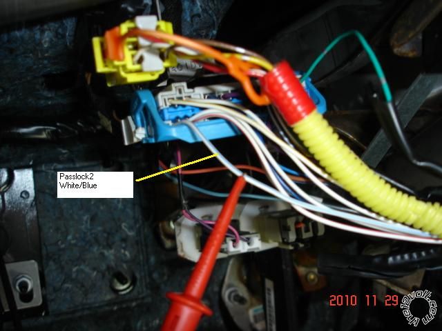
On the FLCAN's connection to the vehicles WHITE/ Blue Passlock2 wire, the FLCAN WHITE/ Black must be on the vehicle side of the cut

Passlock2 wire and the FLCAN WHITE/ Red must be on the connector side ( ignition switch ).

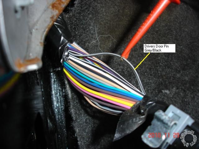
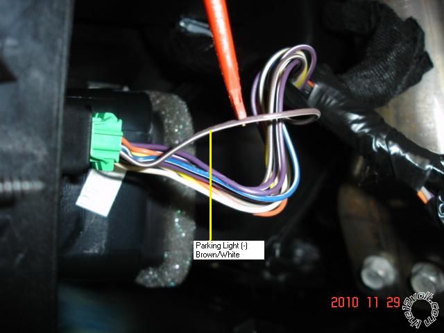
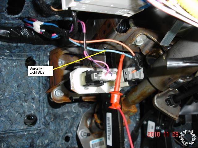
I prefer to go to the firewall connector rather than opening up the steering column.  Here are some photo's :

2006 hummer h3 dei1603 issues - Page 3 -- posted image.

2006 hummer h3 dei1603 issues - Page 3 -- posted image.

2006 hummer h3 dei1603 issues - Page 3 -- posted image.

2006 hummer h3 dei1603 issues - Page 3 -- posted image.

2006 hummer h3 dei1603 issues - Page 3 -- posted image.

Soldering is fun!
macraeauto 
Member - Posts: 23
Member spacespace
Joined: July 20, 2015
Location: Massachusetts, United States
Posted: September 01, 2015 at 7:21 PM / IP Logged Link to Post Post Reply Quote macraeauto
as far as the programming steps its one-one-thousand two-one-thousand three-one-thousand for Each step even when its starting but no indicator light at all on the FLCAN. pretty sure all the connections you mentioned are the same as your second message and in all the same places. gonna slip on the flip flops and go recheck .....
macraeauto 
Member - Posts: 23
Member spacespace
Joined: July 20, 2015
Location: Massachusetts, United States
Posted: September 01, 2015 at 8:10 PM / IP Logged Link to Post Post Reply Quote macraeauto
So I just checked it for the same team time and everything is exactly as you say it should be which is how it is in the diagram. (Great pics by the way)The only thing I even give a second thought to as a problem is the WHITE/ black wire that goes to the vehicle side of the pass lock wire that gets cut. There is also a yellow pass lock wire coming out of the FLCAN I actually hooked up the yellow one first before I realized the white and black was supposed to be connected also so I just tapped into the yellow wire which is going up to the passlock lock cut wire switch Side.   I can't think that should make a difference should it? I have used butt connectors (without doing the heat shrinks - yet) and scotch locks but I've gone around with the power probe and tested both sides of every connection and everything seems good without any opens....i'm going to find a tall bottle of something strong to have a few short glasses of over ice and hopefully go to sleep and hopefully not dream about this truck tonight
kreg357 
Platinum - Posts: 7,783
Platinum spaceThis member has made a donation to the12volt.com. Click here for more info.spaceThis member has been recognized as an authority in Electrical Theory. Click here for more info.spaceThis member has been recognized as an authority in Mobile Security and Convenience. Click here for more info.spacespace
Joined: January 30, 2009
Location: Pennsylvania, United States
Posted: September 02, 2015 at 3:44 AM / IP Logged Link to Post Post Reply Quote kreg357

A few thoughts.  Passlock2 is resistance based and makes all of the connections a bit more critical.  I always solder every connection

and these Passlock2 connections are very important.  I would dump the T-Taps, Scotch Loks and crimp / splice connectors if favor
of a quality solder connection.  The FLCAN's Passlock2 IPC reference connection is also very important.

If all of the wiring is correct and the FLCAN is getting power through the D2D harness from the Viper and can be Factory Reset and

Mode Selected but won't program...  Hate to say it, but are you sure the FLCAN has the GM4 firmware flashed?  One of the reasons
most installer's prefer the iDatalink products is their ease of vehicle programming.  The only way to know for sure which firmware is
loaded is with the ADS USB cable.

As for module to vehicle programming, here is my routine.

First a Factory Reset.  At the end of the reset ( after Step 5 and before Step 6 ), I jump to the Mode Selection procedure because
after Step 5, when the RED LED goes out, it starts doing the single Green LED blink ( for Data Mode ).  At this point you can just
press and hold the programming button until the LED goes solid Green for 2 seconds and then Off.  Now the module is all ready for
the Type 3 vehicle programming procedure.  Just plug in all the harnesses and continue with vehicle programming.

When you say it "Starts and then stalls", is there a Security light on the instrument panel flashing?  Passlock2 disables the fuel supply,

so cranking but no start is the symptom.  However, the Viper, could be shutting down due to Tach issues, etc.  You could try doing the
Remote Start Shutdown Diagnostics to see what caused the shutdown.

Soldering is fun!
macraeauto 
Member - Posts: 23
Member spacespace
Joined: July 20, 2015
Location: Massachusetts, United States
Posted: September 02, 2015 at 8:33 AM / IP Logged Link to Post Post Reply Quote macraeauto
ok - many responses and more questions:
I know this harness between the ignition and the large connector (C201i think -- your first pic) is a hot mess due to this being the SECOND install on this vehicle and that harness is fragile to say the least. but i cant find any issues with the connections, at least not enough to prevent interface. when i am plugged in with my scan tool i can see the fuel DISABLE on the pcm data list is showing "active" only when the RS tries to start, so I know its the PCM's VTD kicking in. and obviously its not getting a signal from the FLCAN cause its not programmed. my number one question is this - actually a two parter: if the RS is not in data mode it can still provide power to the FLCAN, right? because obviously its getting power since i can reset it and set the data mode ( I saw one of you other posts on another thread describing how you set the mode after step 5 of the reset so i Was doing it that way) but using your method in the previous post of grounding the white blue wire did not seem to register any effect on the RS so i am wondering if the RS NOT being in data mode would have any effect on the FLCAN not accepting programming? (I have no way to know if it is or not)Nothing in the larger manual for the Avital RS tells me how to put the RS in data mode. the only thing it says it to hook up the D2D cable BEFORE you hookup the main power harness connector --> with the implication that it will recognize it when it powers up (and go into that mode?) Thats the one thing about the FLCAN- the flashlogic directions are great, much better than the RS ones but they dont specify AT WHAT STEP to do that programming so I assume it is with every thing connected. I know it might be a stretch but i am unfamiliar with how the communication factor plays in until the modules are set up and programmed. As far as the programming of the FLCAN, the seller claims (multiple times) that he has programmed it to the vehicle i have.
I apologize for the rambling nature of my post. trying to keep it organized but all these different possibilities arise and one makes me think of another. I still think the main issue is the FLCAN not being programmed. I feel if this can happen the rest will function correctly. the only part of my install i am uncomfortable with is the door/dome connection (without the recommended diodes) and the giant dotted box that says "mandatory connections failure to comply may result in product malfunction" i just dont get how/why it needs TWO negative inputs on that circuit versus just the door input and if my lack of diodes is a factor at all....
Thank you very much for your help.
Page of 4

  Printable version Printable version Post ReplyPost New Topic
You cannot post new topics in this forum
You cannot reply to topics in this forum
You cannot delete your posts in this forum
You cannot edit your posts in this forum
You cannot create polls in this forum
You cannot vote in polls in this forum

  •  
Search the12volt.com
Follow the12volt.com Follow the12volt.com on Facebook
Thursday, April 25, 2024 • Copyright © 1999-2024 the12volt.com, All Rights Reserved Privacy Policy & Use of Cookies
Disclaimer: *All information on this site ( the12volt.com ) is provided "as is" without any warranty of any kind, either expressed or implied, including but not limited to fitness for a particular use. Any user assumes the entire risk as to the accuracy and use of this information. Please verify all wire colors and diagrams before applying any information.

Secured by Sectigo
the12volt.com spacer
Support the12volt.com
Top
the12volt.com spacer