


 That's with a view to BOTH closing the valve upon exit/lock and reopening upon entry/unlock, and it's in principle only - I'll consider meshing with your two DEI 528Ts later.
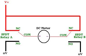
The DEI528Ts might do it alone since they have SPDT relay outputs (I think...
That's with a view to BOTH closing the valve upon exit/lock and reopening upon entry/unlock, and it's in principle only - I'll consider meshing with your two DEI 528Ts later.
The DEI528Ts might do it alone since they have SPDT relay outputs (I think...  ) - and your motor is well under 1A - but I'm looking at the 528Ts self powering off plus integration with your existing manual switch. (Maybe swapping the +12V to the relays' NO contacts and adding a few diodes...?)
The power-off may not be required but I'm assuming the 528Ts use a standard 555 timer and hence present a constant drain of 10mA (hence 20mA total) which tho ok for a vehicle that is run every few days may not be good for a motorhome etc that sits idle for lengthy periods. (Of course a master on-off switch could be fitted to disable the 528Ts when not required for lengthy periods.)
I did look at H-bridge circuits since your valve uses similar or less current than a typical automotive relay (was it 80mA?), but I considered them too impracticable for your application - ie, soldering; non-commercially readily available sparts; etc.
Anyhow, the washing has stopped and it's still 33°C (91°F) outside. Cool!
) - and your motor is well under 1A - but I'm looking at the 528Ts self powering off plus integration with your existing manual switch. (Maybe swapping the +12V to the relays' NO contacts and adding a few diodes...?)
The power-off may not be required but I'm assuming the 528Ts use a standard 555 timer and hence present a constant drain of 10mA (hence 20mA total) which tho ok for a vehicle that is run every few days may not be good for a motorhome etc that sits idle for lengthy periods. (Of course a master on-off switch could be fitted to disable the 528Ts when not required for lengthy periods.)
I did look at H-bridge circuits since your valve uses similar or less current than a typical automotive relay (was it 80mA?), but I considered them too impracticable for your application - ie, soldering; non-commercially readily available sparts; etc.
Anyhow, the washing has stopped and it's still 33°C (91°F) outside. Cool!If you wish to post a reply to this topic, you must first login.
If you are not already registered, you must first register.
 Printable version


| You cannot post new topics in this forum You cannot reply to topics in this forum You cannot delete your posts in this forum You cannot edit your posts in this forum You cannot create polls in this forum You cannot vote in polls in this forum |

| Search the12volt.com |
Follow the12volt.com 
Friday, April 19, 2024 • Copyright © 1999-2024 the12volt.com, All Rights Reserved • Privacy Policy & Use of Cookies

Friday, April 19, 2024 • Copyright © 1999-2024 the12volt.com, All Rights Reserved • Privacy Policy & Use of Cookies
Disclaimer:
*All information on this site ( the12volt.com ) is provided "as is" without any warranty of any kind, either expressed or implied, including but not limited to fitness for a particular use. Any user assumes the entire risk as to the accuracy and use of this information. Please
verify all wire colors and diagrams before applying any information.
