the12volt.com spacer
icon

icbm7071 alarm in 2005 Buick Rendezvous


Post ReplyPost New Topic
< Prev Topic Next Topic >
antman1 
Copper - Posts: 121
Copper spacespace
Joined: February 13, 2012
Location: Tennessee, United States
Posted: September 06, 2015 at 5:29 PM / IP Logged Link to Post Post Reply Quote antman1
Should I connect pin 85 of the relay to the Orange Accessory wire on the heavy main harness? And pin 30 of the relay is just going to go to the Accessory 2 wire on the ignition harness?
Also I was wondering how the EVO-ALL is going to get power? I see the Ignition wire that I am connecting to Ignition 1 on the main harness (I think that is right?), but I dont see a 12v or ground connection.. only the wires to the alarm and the Ignition and OBD2 connection. Am I missing anything there? I will post a pic of my prep I have done when I get back. going for a walk with the kids and will add it to this post as an edit.
antman1 
Copper - Posts: 121
Copper spacespace
Joined: February 13, 2012
Location: Tennessee, United States
Posted: September 07, 2015 at 1:54 AM / IP Logged Link to Post Post Reply Quote antman1
Well I got the wire prep done except that pin 85 of the relay and pin 30 of the relay. Should I connect pin 85 of the relay to the Orange Accessory wire on the heavy main harness? And pin 30 of the relay is just going to go to the Accessory 2 wire on the ignition harness? I put pin 86 and pin 87 to 12v Constant.
I also believe I found out the answer to my question earlier. On the EVO-ALL there is a 4 pin harness that connects beside the 20 pin and I cut the white and Blue wires that are data not being used and connected the red 12v constant and attached the ground wire to the other ground wires I will be connecting. Here are some pics of the prep done so far except the relay is not finished.
icbm7071 alarm in 2005 Buick Rendezvous - Page 3 -- posted image.
antman1 
Copper - Posts: 121
Copper spacespace
Joined: February 13, 2012
Location: Tennessee, United States
Posted: September 08, 2015 at 12:10 AM / IP Logged Link to Post Post Reply Quote antman1
I got all the prep work done. I just put pin 85 from the relay on the Blue/White wire that the EVO-ALL is also using. I dont think it would be a problem.
Now I am just waiting for the Flashlink v2 so I can program it. Hopefully all goes well after that and it will be all done.
kreg357 
Platinum - Posts: 7,783
Platinum spaceThis member has made a donation to the12volt.com. Click here for more info.spaceThis member has been recognized as an authority in Electrical Theory. Click here for more info.spaceThis member has been recognized as an authority in Mobile Security and Convenience. Click here for more info.spacespace
Joined: January 30, 2009
Location: Pennsylvania, United States
Posted: September 08, 2015 at 7:18 AM / IP Logged Link to Post Post Reply Quote kreg357
The external ACC2 relay will be ON as soon as the R/S unit brings up the GWR signal, signifying a remote start is initiated.  As such,
it will not drop the ACC2 output during cranking as is normal when the car is started with the key.  Please take a look at the control
wires going from the R/S unit to the satellite relay pack.  There is a wire in there that was mentioned earlier that will give you the proper
(-) Accessory relay control signal.  That is the control wire I would use for the ACC2 relay.
Soldering is fun!
antman1 
Copper - Posts: 121
Copper spacespace
Joined: February 13, 2012
Location: Tennessee, United States
Posted: September 08, 2015 at 9:40 AM / IP Logged Link to Post Post Reply Quote antman1
I will check that but wouldn't it work just as well if I used the Orange Accessory wire on pin 86 like I did in the past versions of this and still used the Blue/White?
Pin 85 - Blue/White (-) bypass wire in H4 harness and EVO-ALL
Pin 86 - Orange Accessory wire from above
Pin 87 - 12v Constant Fused
Pin 30 - Brown (+) 2nd Accessory wire at ignition switch
Then it would only work at the same time as the first accessory wire instead of having 12v constant.
**EDIT**
Got me a whole new problem I havent run into on other ICBM 7071s' until now. The Alarm is supposed to have a Jumper "JC2" that changes the "Light Flash Output" from positive or negative. By default (According to the Manual) it is Positive. I had this jumper on my alarm unit in the past and was able to change it to Negative on my Town and Country but on this alarm (same model) it is missing. no jumper. I called the number and spoke with a person that said they dont know technical details and that I need to read the manual more and they will send me another copy in case the manual I have is older. Looks like I may need to convert the Positive to Negative somehow (maybe a relay)? Tech support from there site sent the exact same manual to me I already have saying to change "JC2" jumper.
Here is what the Brain looked like inside. I dont see a jumper, the red jumper wire is for Automatic or Manual transmissions:
icbm7071 alarm in 2005 Buick Rendezvous - Page 3 -- posted image.
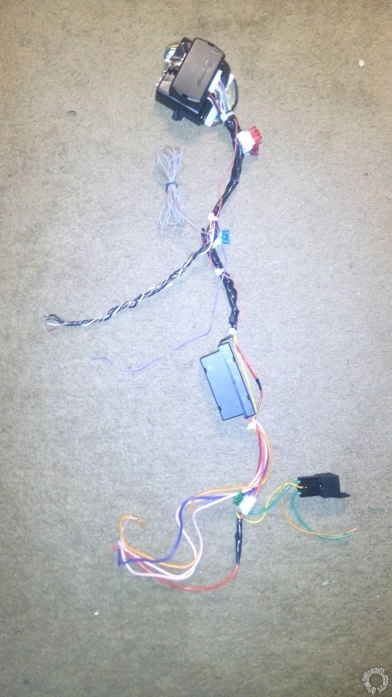
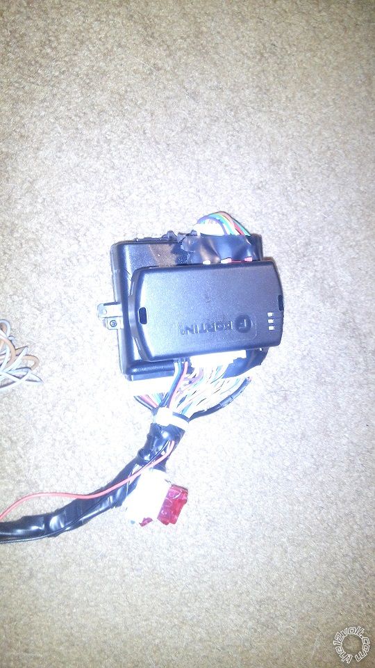
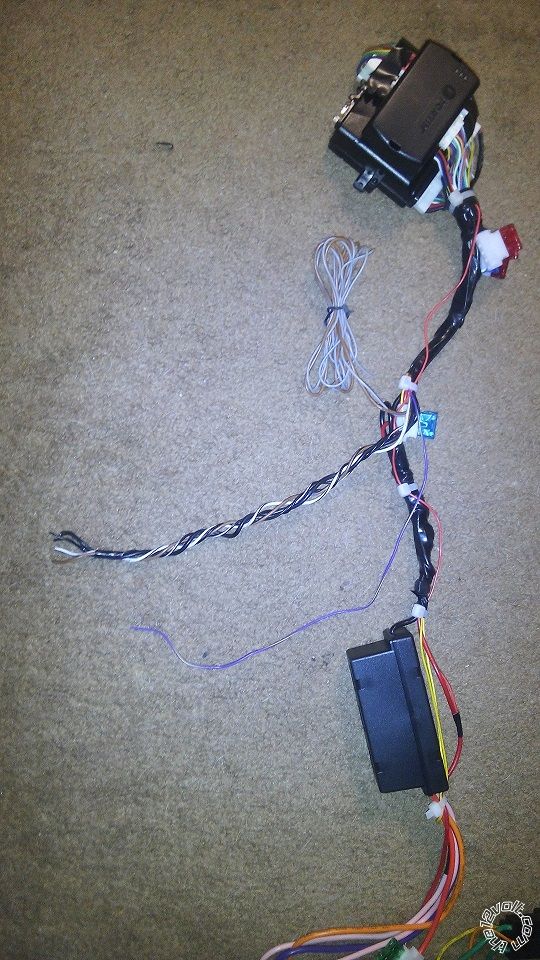
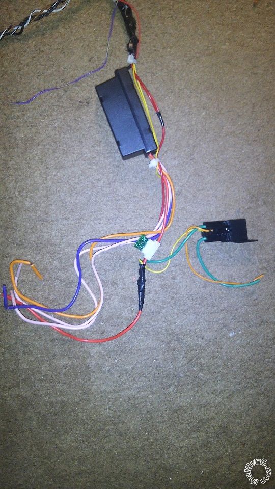
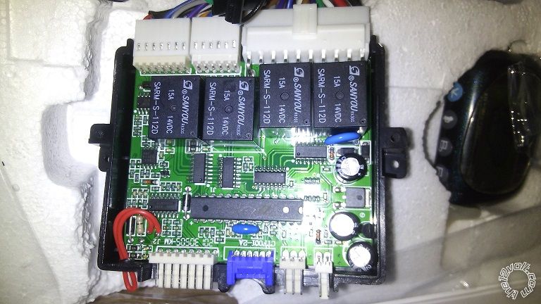
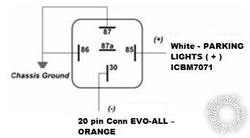
If I cant find a way to make the ICBM7071 use the Negative polarity for the "Light Flash Output" I guess I would have to wire this up, right?
icbm7071 alarm in 2005 Buick Rendezvous - Page 3 -- posted image.
kreg357 
Platinum - Posts: 7,783
Platinum spaceThis member has made a donation to the12volt.com. Click here for more info.spaceThis member has been recognized as an authority in Electrical Theory. Click here for more info.spaceThis member has been recognized as an authority in Mobile Security and Convenience. Click here for more info.spacespace
Joined: January 30, 2009
Location: Pennsylvania, United States
Posted: September 08, 2015 at 8:00 PM / IP Logged Link to Post Post Reply Quote kreg357

I will check that but wouldn't it work just as well if I used the Orange Accessory wire on pin 86 like I did in the past versions of this and

still used the Blue/White?
Pin 85 - Blue/White (-) bypass wire in H4 harness and EVO-ALL
Pin 86 - Orange Accessory wire from above
Pin 87 - 12v Constant Fused
Pin 30 - Brown (+) 2nd Accessory wire at ignition switch

Then it would only work at the same time as the first accessory wire instead of having 12v constant.

The only issue I have with the above relay wiring is sharing the Blue/White (-) GWR signal between a relay coil and the EVO-ALL.

It would be nice if there were two GWR signal available.  In reality, you might not even need to power the Brown ACC2 wire during a
remote start.   The Brown ACC2 might only supply power to non-critical things like the radio, wipers, power windows, etc.

The relay for the Parking Light polarity conversion is OK.  You could skip using the EVO-ALL to control the Parking Lights and go

direct to this vehicle wire :  Parking Lights (+)     Brown (+)       @ BCM, gray 24 pin plug, pin B3

Did you get the EVO-ALL re-flashed yet?

Soldering is fun!
antman1 
Copper - Posts: 121
Copper spacespace
Joined: February 13, 2012
Location: Tennessee, United States
Posted: September 08, 2015 at 10:34 PM / IP Logged Link to Post Post Reply Quote antman1
I havent got the EVO-ALL Reflashed yet. I ordered the Flashlink v2 so I can flash it. waiting on receiving it. Just trying to perfect my prep work on it till then so I can just solder it in and be good to go.
I think I am going to use another relay and still let the EVO-ALL control the Parking lights. I think it is weird this ICBM7071 looks different inside. It is like they changed the board layout and did away with the jumper. Another thing I noticed was different from the other 2 I did is that this one has a Shock sensor separate from the antenna. The other 2 I did had the shock sensor in the Antenna. The manual doesn't account for that either.
kreg357 
Platinum - Posts: 7,783
Platinum spaceThis member has made a donation to the12volt.com. Click here for more info.spaceThis member has been recognized as an authority in Electrical Theory. Click here for more info.spaceThis member has been recognized as an authority in Mobile Security and Convenience. Click here for more info.spacespace
Joined: January 30, 2009
Location: Pennsylvania, United States
Posted: September 09, 2015 at 2:23 AM / IP Logged Link to Post Post Reply Quote kreg357

Having a selectable Parking Light output is a nice feature, but not insurmountable.  Hopefully the updated PCB provides other benefits that make up for this change.  Poor / inaccurate documentation is very common on these "off-shore" brands.

Soldering is fun!
antman1 
Copper - Posts: 121
Copper spacespace
Joined: February 13, 2012
Location: Tennessee, United States
Posted: September 15, 2015 at 11:02 AM / IP Logged Link to Post Post Reply Quote antman1
got the Flash Link today and when I selected my vehicle it recommended firmware 70.15 version. I flashed it to my EVO-ALL. Is that the right firmware as far as the latest and greatest or should I select 4.06 and just flash it instead?
icbm7071 alarm in 2005 Buick Rendezvous - Page 3 -- posted image.
kreg357 
Platinum - Posts: 7,783
Platinum spaceThis member has made a donation to the12volt.com. Click here for more info.spaceThis member has been recognized as an authority in Electrical Theory. Click here for more info.spaceThis member has been recognized as an authority in Mobile Security and Convenience. Click here for more info.spacespace
Joined: January 30, 2009
Location: Pennsylvania, United States
Posted: September 15, 2015 at 6:19 PM / IP Logged Link to Post Post Reply Quote kreg357
The Fortin recommended 70.15 should be fine.  Anything above 70.10, I think will work, as will as the older Ver 4.06.
Soldering is fun!
Page of 5

  Printable version Printable version Post ReplyPost New Topic
You cannot post new topics in this forum
You cannot reply to topics in this forum
You cannot delete your posts in this forum
You cannot edit your posts in this forum
You cannot create polls in this forum
You cannot vote in polls in this forum

  •  
Search the12volt.com
Follow the12volt.com Follow the12volt.com on Facebook
Thursday, April 25, 2024 • Copyright © 1999-2024 the12volt.com, All Rights Reserved Privacy Policy & Use of Cookies
Disclaimer: *All information on this site ( the12volt.com ) is provided "as is" without any warranty of any kind, either expressed or implied, including but not limited to fitness for a particular use. Any user assumes the entire risk as to the accuracy and use of this information. Please verify all wire colors and diagrams before applying any information.

Secured by Sectigo
the12volt.com spacer
Support the12volt.com
Top
the12volt.com spacer