the12volt.com spacer
icon

remote start, 1990 ford festiva


Post ReplyPost New Topic
< Prev Topic Next Topic >
stefanr 
Member - Posts: 9
Member spacespace
Joined: January 09, 2008
Location: Manitoba, Canada
Posted: January 20, 2008 at 11:15 AM / IP Logged  
Hi guys. This is my first time installing a remote start so id like to doubble check on a couple things.
Im installing a viper 5900
remote start, 1990 ford festiva -- posted image.
These are ths ignition wires i have,
five heavy wires;
white = battery feed
blue/red = accessory (voltage in acc & on)
BLACK/ red = on (voltage in on)
BLACK/ white = ignition feed (voltage in on & start)
BLACK/ blue = start (voltage in start)
I think i got it all figured out except for purple and green. Do i cut the balck/blue start wire and put purple on the starter side and green on the key side?
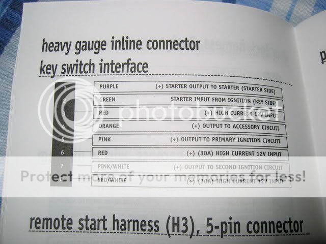
Remote start harness // Ignition circuit
Purple ?
Green ?
Red -> White
Orange -> Blue/Red
Pink -> BLACK/ White
Red -> White
Pink/White -> N/A?
RED / White -> White
The only other connection is BLACK/ red = on (voltage in on)Do i need to energize this too? Perhaps using the 2nd ignition wire on the realy satelite?
GregK 
Copper - Posts: 74
Copper spacespace
Joined: December 30, 2003
Location: Manitoba, Canada
Posted: January 20, 2008 at 11:43 AM / IP Logged  
What is the vehicle you're installing it in?
Just to make sure you don't have any of the wires wrong.
KarTuneMan 
Platinum - Posts: 7,056
Platinum spaceThis member has made a donation to the12volt.com. Click here for more info.spaceThis member consistently provides reliable informationspace
Joined: December 14, 2004
Location: Isle Of Man
Posted: January 20, 2008 at 12:08 PM / IP Logged  

Remember to include the year make and model of your car when posting.....makes us helping that much easier!

Purple and green are for the built in anti grind/starter disable. As it says.... the green one goes to the key side of the cut starter wire

and the purple to the other.

stefanr 
Member - Posts: 9
Member spacespace
Joined: January 09, 2008
Location: Manitoba, Canada
Posted: January 20, 2008 at 1:21 PM / IP Logged  
1990 Ford Festiva... lol
yea i thought i had the PURPLE / green right.
Now im just not sure if i need to do anything with the BLACK/ red = on (voltage in on)wire. Do i use the 2nd ignition wire here?
thanks guys
stefanr 
Member - Posts: 9
Member spacespace
Joined: January 09, 2008
Location: Manitoba, Canada
Posted: January 20, 2008 at 1:31 PM / IP Logged  
Aswell, the power lock outputs on the viper, are they low current for driving relays, or can they be used to run actuators directly. I cant find anything about those outputs in the manual.
I installed power locks way back with a pair of 2 wire actuators and 2 5 pin relays.
GregK 
Copper - Posts: 74
Copper spacespace
Joined: December 30, 2003
Location: Manitoba, Canada
Posted: January 20, 2008 at 3:53 PM / IP Logged  
12 VOLT CONSTANT WHITE (+)              IGNITION SWITCH HARNESS       STARTER       BLACK/ BLUE (+)       IGNITION SWITCH HARNESS      
IGNITION 1       BLACK/ WHITE (+)       IGNITION SWITCH HARNESS      ACCESSORY /HEATER BLOWER 1       BLUE/RED (+)       IGNITION SWITCH HARNESS      
PARKING LIGHTS ( + )       RED / GREEN (+)       IN DRIVERS KICK PANEL      
DOOR TRIGGER       RED / BLUE (-)       IN DRIVERS KICK PANEL      
DOMELIGHT SUPERVISION       USE DOOR TRIGGER, Requires Part #775 Relay       HORN       GREEN (-)       @ STEERING COLUMN HARNESS      
TACH       YELLOW /GREEN       @ IGNITON COIL      
BRAKE       GREEN/ RED (+)       @ SWITCH ABOVE BRAKE PEDAL      
The output for the door locks is to drive relays. 250mA draw I believe.
GDK Electronics
Home theatre & mobile electronics installations
Winnipeg, MB
GregK 
Copper - Posts: 74
Copper spacespace
Joined: December 30, 2003
Location: Manitoba, Canada
Posted: January 20, 2008 at 3:56 PM / IP Logged  
Sorry, first one came out all messed up.
12 VOLT CONSTANT WHITE (+) IGNITION SWITCH HARNESS     
STARTER       BLACK/ BLUE (+)       IGNITION SWITCH HARNESS
IGNITION 1       BLACK/ WHITE (+)       IGNITION SWITCH HARNESS   
ACCESSORY /HEATER BLOWER 1       BLUE/RED (+)       IGNITION SWITCH HARNESS
PARKING LIGHTS ( + )       RED / GREEN (+)       IN DRIVERS KICK PANEL      
DOOR TRIGGER       RED / BLUE (-)       IN DRIVERS KICK PANEL
DOMELIGHT SUPERVISION       USE DOOR TRIGGER, Requires Part #775 Relay
HORN       GREEN (-)       @ STEERING COLUMN HARNESS       
TACH       YELLOW /GREEN       @ IGNITON COIL       
BRAKE       GREEN/ RED (+)       @ SWITCH ABOVE BRAKE PEDAL      
The output for the door locks is to drive relays. 250mA draw I believe.
GDK Electronics
Home theatre & mobile electronics installations
Winnipeg, MB
stefanr 
Member - Posts: 9
Member spacespace
Joined: January 09, 2008
Location: Manitoba, Canada
Posted: January 21, 2008 at 12:45 AM / IP Logged  
thanks guys
few more questions... on the main harness.. what on earth do i do with the WHITE/ blue remote start (-) activation input.
Also if i hook up the dome supervision... to turn on the dome i would have to ground the neg side.. which is the same as opening up a door.. will this confuse the alarm at all?
also, how should i bypass the clutch switch?
before anyone has kittens about remote start+MTX, the car has a factory neutral gear position switch on the trans that ive wired into the neutral safty wire on the alarm so all is good. the wire showed +12 when in neutral so i reversed the polarity with a relay.
brhaugen 
Copper - Posts: 275
Copper spacespace
Joined: September 30, 2005
Location: North Dakota, United States
Posted: January 21, 2008 at 6:21 AM / IP Logged  
The WHITE/ blue is used to start the vehicle without the remote.
Use this if you want to start the starter from another device (alarm etc.)
I have hooked these up to a push button under the dash for delivery trucks.
You should be ok hooking up the dome light, I doubt Viper would design something that could set itself off.
You have to test the switch and duplicate it's function with a relay.
PLEASE double and triple check your neutral safety setup.....
stefanr 
Member - Posts: 9
Member spacespace
Joined: January 09, 2008
Location: Manitoba, Canada
Posted: January 21, 2008 at 11:44 AM / IP Logged  
brhaugen wrote:
You have to test the switch and duplicate it's function with a relay.
where do i get current to activate the relay when the remote start activates?
Page of 2

  Printable version Printable version Post ReplyPost New Topic
You cannot post new topics in this forum
You cannot reply to topics in this forum
You cannot delete your posts in this forum
You cannot edit your posts in this forum
You cannot create polls in this forum
You cannot vote in polls in this forum

  •  
Search the12volt.com
Follow the12volt.com Follow the12volt.com on Facebook
Thursday, April 18, 2024 • Copyright © 1999-2024 the12volt.com, All Rights Reserved Privacy Policy & Use of Cookies
Disclaimer: *All information on this site ( the12volt.com ) is provided "as is" without any warranty of any kind, either expressed or implied, including but not limited to fitness for a particular use. Any user assumes the entire risk as to the accuracy and use of this information. Please verify all wire colors and diagrams before applying any information.

Secured by Sectigo
the12volt.com spacer
Support the12volt.com
Top
the12volt.com spacer