light led at specific resistance?
Printed From: the12volt.com
Forum Name: General Discussion
Forum Discription: General Mobile Electronics Questions and Answers
URL: https://www.the12volt.com/installbay/forum_posts.asp?tid=110766
Printed Date: March 18, 2026 at 3:20 AM
Topic: light led at specific resistance?
Posted By: astrosurfer
Subject: light led at specific resistance?
Date Posted: January 18, 2009 at 12:22 AM
Hi fellas.
Been a few months since my last visit.
Now I have a burning Q.
I am wondering if there's a way to incorporate a warning led into my fuel sender circuit to come on at a specific low level.
I'm sure the resistance from the sender changes and that's why the gauge changes.
I'd like a warning when fuel low like newer vehicles do.
Obviously all help appreciated.
Any diagram will help and list of components.
I'm thinking some sort of transistor setup would work but also thinking they work on voltage increase. Not real sure.
Thanks
Replies:
Posted By: james bond 007
Date Posted: January 18, 2009 at 9:49 PM
If your gauge works with voltage, you could use a zener diode
Posted By: astrosurfer
Date Posted: January 25, 2009 at 10:12 PM
OK
I have a little more info I can add
my fuel sender sends 240 ohms empty and 33 ohms full to my gauge.
Looking for a way to turn on a warning at say 180 ohms. Is this possible guys?
Again thanks.
I'm looking into the zener diode but I don't understand it.
Posted By: howie ll
Date Posted: February 04, 2009 at 5:17 PM
Mr. Bond is I think right, at empty it's returning a lower voltage than full, say 3 against 6 so a zner driving the LED selected at say 3 volts would light an LED. Raise the voltage, the Zener opens the circuit, LED turns off. I'm sure I am an Idiot or Mr. Pearson could enlighten you more if you pm them.
Posted By: astrosurfer
Date Posted: February 06, 2009 at 7:54 PM
thanks for more info dude.
I am really uneducated on zeners for sure.
I did not know they did this.
I'll pm idiot....or mr.pearson and see if they could give me some more insight into this.
Thank you very much indeed.
And to MR BOND. Thanks.
Posted By: i am an idiot
Date Posted: February 06, 2009 at 9:24 PM
Instead of the ohm reading of the unit, can you give me a voltage reading at whichever end of the range is easier. Full or empty will work. Black meter lead to ground and the red lead to the output wire of the sending unit, or the input wire of the gauge. Meter set to DC volts.
Posted By: KPierson
Date Posted: February 06, 2009 at 11:02 PM
Who is this Mr. Pearson character? I'm with I am an idiot on this one, voltage is the route to go, not resistance. ------------- Kevin Pierson
Posted By: howie ll
Date Posted: February 07, 2009 at 1:20 AM
Kevin. sorry I'm the guilty party.
Posted By: KPierson
Date Posted: February 07, 2009 at 7:39 AM
haha, not a problem at all!
-------------
Kevin Pierson
Posted By: i am an idiot
Date Posted: February 07, 2009 at 5:52 PM
The Op amp in the diagram is a LM741 (NTE 941) single channel op amp. If you can not find one I can get an LM358 (NTE 928M) for you. It is a 2 channel op amp but you will only have to move power from pin 7 to pin 8 on the 358. If you can tell me what voltage you want the light to light up at, I can modify the adjustment pot to give you more precise control. Southern Radio 355-0396 or Ralph's Industrial Electronics 344-3761 should have the NTE parts. https://www.the12volt.com/installbay/forum_posts.asp?tid=105885&KW=i+am+an+idiot The part about the light coming on when 3 gallons remaining, you have to adjust it for that to happen.
Posted By: astrosurfer
Date Posted: February 21, 2009 at 10:21 PM
thanks..
I'll look into all that...
sorry bout delay but been very busy.
Posted By: astrosurfer
Date Posted: February 23, 2009 at 5:12 PM
OK
Been looking into this in more detail.
I looked at the schematic above and have a question.
What I have controling my gauge is a resistance range of 0-90 ohms. 90 being full tank.
The wire going to the gauge (which has 12v and ground ) measures no voltage on my DMM only resistance.
So I take out my cluster again. Did some measuring and find the above details.
So I'm back to needing to turn on a light at 20 ohms.
Does the above suggested schematic still work?
Posted By: i am an idiot
Date Posted: February 23, 2009 at 8:05 PM
There has to be voltage to power the gauge. Are you using a digital meter to read voltage?
Posted By: astrosurfer
Date Posted: February 23, 2009 at 9:33 PM
yes I am
The fuel gauge has 3 terminals.
+12v
Gnd
resistance input.
I don't understand it myself....but it seems that the gauge has 12v and ground.
Then resistance across the slosh to ground triggers the gauge.
The less resistance the lower the gauge reads.
With it out of the car I had it wired with 12v supply, and ground.
This sends the needle over the full to max.
Applying resistance between 0-90 ohms makes the gauge act accordingly. but only across ground and slosh wire.
I am slightly confused by this.
Posted By: KPierson
Date Posted: February 23, 2009 at 10:44 PM
I would set the gauge so that it reads half way. Then, recheck the voltage between the ground terminal and the resistance input right at the gauge. Since a change in resistance will cause a change in voltage I think you should be seeing between the actual resistance input and sensor ground.
-------------
Kevin Pierson
Posted By: astrosurfer
Date Posted: February 25, 2009 at 6:26 PM
ok
I will try that and report my findings...I hope I am understanding you right.
90 ohms is not alot to change 12v though is it?
Posted By: KPierson
Date Posted: February 25, 2009 at 6:56 PM
90 ohms by itself won't be enough to change the voltage, but 90 ohms paried with a second resistor would. Most systems that use a resistive based sensor use what is called a "voltage divider". The voltage divider is two resistors wired in series from 12vdc to ground. The output voltage between the two resistors can vary drastically as the resistance of one resistor changes. The key here is to keep the second resistor consistent, then you can use the voltage between the sensor to represent the value, as voltage, of whatever you are trying to read. Something else you may try is measuring the resistance between the input of the guage and the 12vdc pin. If you can figure out the resistance of the second resistor (assuming they are using a voltage divider) then you can actually calculate the voltage at any point, and then set up a comparator circuit to work. This would have to assume the gauge is operating at 12vdc and not 5vdc and is probably a long shot because of this. For accuracy and repeatability you would want to feed the sensor with a stable voltage, so I wouldn't be surprised if it did have a 5vdc regulator driving it. Speaking of comparator circuits, I just built one yesterday using an LM324 from Radioshack. Pretty straight forward little circuits. Anyway, back to your situation - there are two reasons I strongly believe that you are working with a voltage divider 1. that is the typical way to interface a resistive sensor and 2. because your sensor goes to 0 ohms. Almost any other type of interface would be damaged by the sensor essentially shorting to ground. However, if there is a second resistor in series with the 0 ohm sensor then the power supply won't actually be shorted. ------------- Kevin Pierson
Posted By: astrosurfer
Date Posted: February 26, 2009 at 5:52 PM
LOL
all french to me dude.
But I am going to do what you suggest.
I think I sort of understand what you mean.
I am truly miffed by this one though.
Posted By: astrosurfer
Date Posted: March 04, 2009 at 9:12 PM
OK
back with some findings
I find that I have voltage out on my resistance terminal.
varies between 2.75 volts with 15 ohms bridged
and @ 82 ohms I have 6.22 volts at the resistance terminal.
So I'm thinking that i am an idiot's circuit will work for me.
or does that not figure right?
So I'd like to turn the light on at say 2.5 volts.
That'd be around 12.5 ohms.
Posted By: i am an idiot
Date Posted: March 05, 2009 at 12:57 AM
That is what that circuit is designed to do. Fill the tank to the level in which you would like it to light up at, and adjust the potentiometer until it lights up. Add a gallon of fuel and make sure it goes off. If the pot is too touchy to get accurate, when I am actually awake I will figure out a voltage divider and a smaller pot so you can get it more accurate.
Posted By: astrosurfer
Date Posted: March 07, 2009 at 12:45 AM
OK
That circuit works but it's very hard to set the pot.
very jumpy indeed.
Is there another less drastic pot I can use for this?
Thanks a bunch fellas
Posted By: i am an idiot
Date Posted: March 07, 2009 at 3:41 AM
I need better info on the voltage readings. You stated earlier that your range of voltages were from 2.75 to 6.22. You then stated that you want it to light at 2.5 volts. Is the 6.22 and the 2.75 not completely full and completely empty? I can make it come on at whatever voltage you desire. I just noticed that your desired voltage did not fall in the range you posted. Clear that up and I will figure it out this evening.
Posted By: KPierson
Date Posted: March 07, 2009 at 6:29 AM
As long as you can handle not being able to set the value above 5vdc I would use a voltage regulator on the pot. The 7805 has three pins - in, out, and ground. Connect the in to switced ignition, connect the ground to ground, and then connect the out to the "voltage in" pin on the pot. If you want to "do it right" you should also add a cap across the input and a cap across the output (check the data sheet for the recomended type and value). This will limit the range of the pot from 0-5vdc and, more importantly, it will eliminate the flucuation on the op amp input caused by the unstable voltage of the vehicles electrical system. If you are having trouble dialing the pot in you may want to look for a higher quality pot or a pot with more turns. On the last circuit I built I used a pot from Alpha that was a single turn (270 degrees from end to end) and I could adjust it to the hundreth of a volt between 0-5vdc rather easily. ------------- Kevin Pierson
Posted By: i am an idiot
Date Posted: March 07, 2009 at 5:05 PM
i am an idiot wrote:
If the pot is too touchy to get accurate, when I am actually awake I will figure out a voltage divider and a smaller pot so you can get it more accurate.
If you go the 7805 route, you will have to buy a new pot and also have to sink and mount the regulator. Or we could use 1 or 2 resistors and a different value pot. No heat sink no worries about mounting the heat sink and the IC.
Posted By: astrosurfer
Date Posted: March 07, 2009 at 5:33 PM
OK fellas
Like I say...I have the dash out of my project car.
I worked this last night and the circuit lit the led just fine.
I had 2 values from the pot...
I'd like to just make it a set value seeing as I know when I need to turn it on at.
I will get that value later on.
Not at my bench right now.
It seemed to turn on at around between 1/4 and Empty.which is where I want. It was just a bitch setting the pot because it jumps large figures.
I was also using a pot to set my gauge. (with the info from you guys about the value difference I should be seeing across my gauge.)
I made the circuit exactly though the first time I had a resistor as my slosh wire, but I realised that was wrong coz the LED would not go out...stayed on no matter what.
So I figured I'd better set it up with my gauge and all.
That's when the circuit worked...with the actual voltage from the slosh wire.( I had 15 ohms across my gauge as a mock slosh wire like it was still in the vehicle)
To fine tune this I'd really like to get the values right and make a fixed setup with no trimming required.
I have a few folks interested in this and we have the same vehicles.
All 0-90 ohm resistance senders. Basically all firebird/trans am owners.
Anyway the readings I will post shortly from either side of the 10K pot.( I assume it's a 10K pot..lol)
Anyway it works and I just need to finetune it for my specific vehicle without any trimming. Plug and play if you like.
Thanks again fellas
Posted By: KPierson
Date Posted: March 07, 2009 at 6:08 PM
i am an idiot wrote:
If you go the 7805 route, you will have to buy a new pot and also have to sink and mount the regulator. Or we could use 1 or 2 resistors and a different value pot. No heat sink no worries about mounting the heat sink and the IC.
Why would you need a different pot and why would you need a heat sink? I just did this the other day with a 10K pot and a 100mA 7805 with no heat sink. Works great. The pot will only draw 1/2mA, WAAAAAAAAAAYYYYYYYYY below the point of needing a sink (typically 100mA is the point of adding a heat sink). If you want to eliminate the pot and just use a voltage divider circuit you should still use a 5vdc regulator to power the voltage divider circuit. Your battery voltage will bounce around from ~10-~15vdc while driving depending on a multitude of conditions. Having a voltage regulator will insure that you ALWAYS have 5vdc going in to the voltage divider (or pot) and will eliminate the effects of the unstable voltage. I would guarentee the guage has a voltage regulator inside it to provide consistency in reading the level sensor, so why not include this "feature" in the circuitry to light the light? ------------- Kevin Pierson
Posted By: astrosurfer
Date Posted: March 07, 2009 at 8:27 PM
I think I would like to make the resistance across the pot be fixed at what makes the light come on now. I think it was like 5K.
That circuit does what I need.
Could I sub the pot for a 5K and test that way.
I guess nothing is ever discovered if it's never tried eh?
It would merely make the light come on when sender reaches a specific point instead of a user variable point, correct?
Posted By: i am an idiot
Date Posted: March 07, 2009 at 9:20 PM
If you can not tell me what voltage the resistance lead of the meter has on it when you are at the desired level of fuel, I can not answer your question. You earlier said that the range of the gauge was from 6.22 volts to 2.75 volts. Then you said you wanted it to come on at 2.5 volts. That is not within the range of what you said the gauge operated at. The following diagram includes a resistor and a zener diode used as regulation. The pot has been replaced with 2 fixed resistors. They will make the light come on at 2.5 volts. If you need to have the light come on with less voltage, change the bottom resistor to a slightly lower value than the 1K. If you need the light to come on at a higher voltage, replace the 1K with a resistor with a slightly higher than 1K. 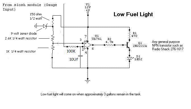
Posted By: i am an idiot
Date Posted: March 07, 2009 at 10:02 PM
If you insist on using the 7805 here is how you would do so. The left leg of it needs to be connected to power. Notice the A in the 2 boxes, connect those together. 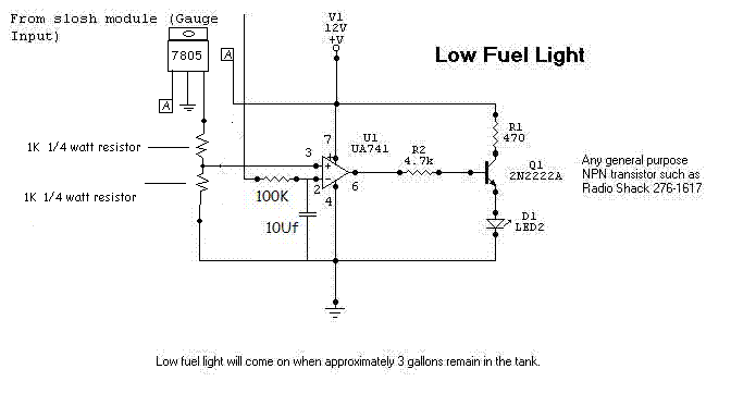
Posted By: astrosurfer
Date Posted: March 08, 2009 at 3:23 AM
With 13.5 volts getting to the gauge power wires I have 9.6 volts on the slosh terminal.
The first circuit mentioned on page 1 works fine.
It works with a 3K pot too.
Posted By: i am an idiot
Date Posted: March 08, 2009 at 9:36 AM
Simply changing the value of the pot is going to do nothing to make it easier to calibrate. It will work with a 1K or a 100K pot as well. It will still be just as hard to get it to come on at the precise level you want it to come on. If I could ever figure out the voltage that you want it fo come on at, we can add resistors above and below the pot so that the pot instead of having a range of 9.6 down to 0, we could make the effective range of the pot say from 2 to 3 volts. That would make it much easier for you to get it exactly where you want it. First you said it was hard to set it exactly, then I asked for a voltage. You gave a range of voltages, then your desired voltage did not fall into that range. I asked for clarification, now all of a sudden we are changing to 3K pots. If it needs to be easier to set, I can help you with that when I get a desired voltage number. If it is too hard to calibrate, I need a number.
Posted By: astrosurfer
Date Posted: March 08, 2009 at 12:22 PM
I put those values last night.
PLease don't think I'm trying to change the circuit...that's way wrong.
I'm simply using the components I have here trying to figure out exactly what info I need to give you man.
I am literate with this but not greatly.
I've been trying to get you the figures you need but I get diff values each time I try.
So with that said...I believe the data I gave last night are the definitive figures I have to work with.
It's possible that my mimicking the sender with a pot is also giving me a little hassle.
However I have to because the gauge is not in the car.
Here's my situation....
If I bridge the gauge input (slosh) wire with 15 ohms across GND the light comes on in the circuit.
If I then switch to 16 ohms across GND the light stays off.
This gives me the point that I want the light to operate at. The voltage output at the slosh wire when the sender reads 15 ohms. That is around the 1/4-E level.
I am also getting weird readings on my DMM.
I'm thinking I need to look at that too possibly batteries as it reads higher ohm readings than it should. Like 1 ohm is reading as 16 across all the resistors in the strip and other values are reading higher too.
My original value range was apparently wrong and sorry for any confusion. I'm trying to give as accurate information as I can.
Thanks
Posted By: i am an idiot
Date Posted: March 08, 2009 at 1:22 PM
Place a 100K resistor north of the potentiometer and place a 10K directly south of it. Keep adding 10K resistors south of the pot (in series) untill you get it to a controllable level. This will allow your pot to have way more control and make it easier to set. The adding of the resistors will determine what voltage the pot affects. 2 to 3 3 to 4 volts. Each 10K will not change the range by 1 volt. It is just an example. The above is assuming that the voltage lowers as the fuel burns out of the tank.
Posted By: i am an idiot
Date Posted: March 08, 2009 at 7:05 PM
The 2 green arrows are adjustable. The bottom arrow is the potentiometer, the top one is the amount of fuel in the tank. This demo is assuming that at empty, the sending unit goes all the way to ground. https://www.bcae1.com/temp/lowfuelindicator01.swf
Posted By: astrosurfer
Date Posted: March 08, 2009 at 10:15 PM
Yeah the voltage drops as fuel burns from the tank. And I believe the resistance actually goes to 0 at empty.
I'll try the extra resistors.
I was excited when it actually worked.
You guys are some smart dudes I tell ya.
nice little demo there.
Makes it easier to understand what's actually going on.
Thanks for all the help.
Posted By: dualsport
Date Posted: March 14, 2009 at 10:17 AM
If you're having problems with the indicator flickering as opposed to your just being unable to easily set the threshold, you need to add a small resistance between the comparator output and the positive input of the comparator.
The positive feedback will introduce hysteresis, which is needed when the comparison range is too noisy or touchy.
The bottom line on that neat swf demo mentions it.
When you do this, what happens is that the fuel level will have to rise to a higher level beyond the normal threshold before the LED turns off, and once it's off, it won't turn back on until it drops to a level lower than the normal threshold. This effect keeps it from flickering when it's sitting right at the setpoint.
Unless you have very clean signals, it's always a good idea to have the hysteresis to keep it from toggling back and forth erratically.
If your concern is not a matter of it flickering, but just that you can't twiddle the pot to the right setpoint, maybe because the pot is not smooth: determine the approximate range you're setting it to, and then substitute a fixed resistance in that range but lower in value, and then put a new pot in series with it, with a smaller range, such as 500 ohms or so.
Then a single turn of the pot will be much finer in adjustment, and you should have no problems adjusting it. It's simply a matter of picking a fixed value close to where you want to adjust it, and then adding in a low range pot to do the fine tuning.
|