Adding a Second Battery
Printed From: the12volt.comForum Name: General Discussion
Forum Discription: General Mobile Electronics Questions and Answers
URL: https://www.the12volt.com/installbay/forum_posts.asp?tid=115004
Printed Date: May 03, 2024 at 10:47 PM
Topic: Adding a Second Battery
Posted By: dunn256
Subject: Adding a Second Battery
Date Posted: July 11, 2009 at 2:34 PM
I have a 2003 gmc sierra and i need to install a second battery there is a spot passenger side for it i was wondering the best way to wire it because i need the second battery for my snow plow
thanks
-------------
presicon audio
Replies:
Posted By: dunn256
Date Posted: July 19, 2009 at 10:03 AM
-------------
presicon audio
Posted By: ~pj~
Date Posted: July 19, 2009 at 12:34 PM
Posted By: hemiboy29
Date Posted: August 25, 2009 at 3:13 PM
Posted By: muleshaft
Date Posted: September 18, 2009 at 5:44 AM
Posted By: tommy...
Date Posted: September 18, 2009 at 8:48 AM
-------------
M.E.C.P & First-Class
Go slow and drink lots of water...Procrastinators' Unite...Tomorrow!
Posted By: tommy...
Date Posted: September 18, 2009 at 8:50 AM
-------------
M.E.C.P & First-Class
Go slow and drink lots of water...Procrastinators' Unite...Tomorrow!
Posted By: dunn256
Date Posted: September 20, 2009 at 12:47 PM
-------------
presicon audio
Posted By: hemiboy29
Date Posted: September 20, 2009 at 10:44 PM
Posted By: katman
Date Posted: September 24, 2009 at 3:37 PM
I made a dual battery charging system for my motorcycles and scooters so I never have to worry about the start battery failing due to accessory power draw. I use the Odessey PC-680 (AGM Type Battery) as the aux. or House battery. Used a system designed for boating from BEP Marine that incorporates three switches and a VOLTAGE SENCING RELAY to charge the Aux. / House battery when the alternator is putting out 13.8 volts or better. That way my start battery is always charged up first.
I mounted the battery and charging system in a UM-1 size battery box commonly used in trolling motor applications for fishing boats. Used a quick disconnect plug (50 amp) between the start battery and the dual battery charging system in the battery box so I can move it between my vehicles. I'm making a fuse box that incorporates quick disconnect harness from DEL CITY ELECTRIC SUPPLY (toll free: 800-654-4757) which has 3 ea 12ga wires and 5 ea. 16 ga. wires. A harness with matching quick disconnect plug delivers fused circuits to the front and another one delivers fused power to the rear of the bikes and scooters.
The Odessey PC 680 is a dual purpose battery (deep cycle and starting) that will turn over an eight cyl. engine. The control switches have a series parallel switch that will help start the engine using both batteries in an emergency. There is a switch for each of the batteries. On most vehicles you wire the dual charging system using the output of the charging system so the START battery switch must remain ON. The Aux. / House battery power can control all your accessories with the House Battery Switch. The dual battery charging system runs about $150 on line the Odessey PC-680 runs about $110 delivered. I photocopied the instructions and laminated them to keep a copy in the battery box JUST in case.
I am an experienced electrician so the design and installation work wasn't to bad. The average guy could have a difficult time making a system like this work. The box is mounted to the floor of my scooters (have 3 of the same scooter which have 400 watt alternators in it's 250 c.c. engine.)
-------------
"All paid jobs absorb and degrade the mind."
Aristotle
Posted By: salden77
Date Posted: November 26, 2009 at 11:24 AM
-------------
salden77
Posted By: oldspark
Date Posted: November 26, 2009 at 11:52 PM
The 150A relay cost AUD$15.
It connects the aux battery whenever the vehicle is charging.
I have a $7 50A circuit breakers at each end.
I also have a $25 under-voltage 80A latching cutout from the aux battery to its loads.
I was using the same circuit (adjusted for 13.5V) for the charge-sense connection until I replaced it with the relay.
Normally I'd just use a 30A setup, but a manual switch allows paralleling of my weaker front battery during extreme cranking (CB upgrade pending if required).
Posted By: jimmy poulin
Date Posted: November 28, 2009 at 4:55 PM
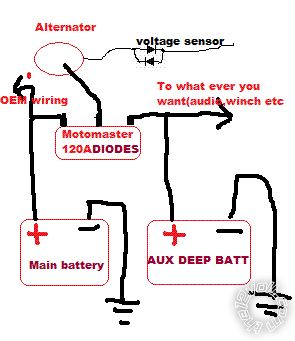
Simply use low cost schottky diode in line with the alternator, battery or line you want to isolate. Go look on eBay, digikey or other electronic store. They go from 400A to 0.0001A in a wild variety of voltage and price. You also can stalk them in parallel for more amp. The voltage drop is 0.3-1 volt but typically 0.7. If this lost is too much for you or you want a sightly higher voltage and a easily confuse with electronic. On GM, put normal diode parallel side up to side down on the voltage sense wire. and you have almost 1 volt more!!!-=-
Posted By: oldspark
Date Posted: November 28, 2009 at 6:19 PM
But if Schottkys have lower voltage drop and Germaniums aren't obtainable, the fine.
But a diode will not prevent the original battery discharging into the second if the second fails.
And the second is likely to fail if constantly subject to a lower charge voltage than the first (ie, via a diode).
I recommend the relay option above. A cheap 15A or 30A relay should be fine for smaller batteries (I have used them for car batteries).
If the batteries are adjacent to each other, fuses/breakers are not required - except to protect the relay.
It only connects the batteries whilst charging.
The same relay else other battery interconnection can be used to parallel the batteries if required (ie, for cranking),
Parallel batteries should be avoided.
Keep in mind that a parallel battery halves the battery's reliability.
PS - tweaking the "sense" wire works for most alternators except the D+ only types (AFAIK).
Sense-wire boosters and other circuits are used by Rally drivers & audio buffs for maximum system voltage hence maximum headlamp brightness, audio power etc. (Once even maximum spark before CDIs!)
Typically they would raise the system voltage to 14.4V at the battery where 14.4 was the common max battery charge voltage; higher where battery life was not as important.
It is the same reason many cook their batteries. If the sense wire is lower than the battery voltage due to intermediate loads (lights, wipers, brakes etc), the regulator will boot output an equivalent amount. A voltage drop of 1.5V can mean 15.9V at the battery - hence overcharging and possibly damaging other loads. (Hence why special care is needed with most two-wire systems - ie IGN & charge Lamp aka Ig or S & L etc.)
Posted By: jimmy poulin
Date Posted: November 28, 2009 at 8:30 PM
Posted By: oldspark
Date Posted: November 28, 2009 at 11:48 PM
And any loads off the alternator handle the extra voltage (ie, as per Rally setups.)
I was assuming a standard load/battery sharing arrangement whilst charging with equal system voltage.
How does the dual diode cost compare to a relay (which I estimate to be $15 for 150A).
And what about heatsinking requirements - are the diodes easy to isolate from the heatsink?
Posted By: katman
Date Posted: November 29, 2009 at 3:08 AM
IÍ wanted to find a high amperage LATCHING RELAY. Where did you find one
and what did it cost? Wanted to keep my HID lighting ballasts off when I
start the engine then bring them on to avoid problems with them.
oldspark wrote:
I use an ordinary relay instead of complex equipment.
The 150A relay cost AUD$15.
It connects the aux battery whenever the vehicle is charging.
I have a $7 50A circuit breakers at each end.
I also have a $25 under-voltage 80A latching cutout from the aux battery to its loads.
I was using the same circuit (adjusted for 13.5V) for the charge-sense connection until I replaced it with the relay.
Normally I'd just use a 30A setup, but a manual switch allows paralleling of my weaker front battery during extreme cranking (CB upgrade pending if required).
-------------
"All paid jobs absorb and degrade the mind."
Aristotle
Posted By: katman
Date Posted: November 29, 2009 at 3:21 AM
Forgot to mention I have a Honda bike. It has a 400 watt alternator @ 5,000 rpm. Puts out 15.2 volts at peak output. This is good with the PC-680 Odyssey as the sencing relay and associated wiring drops the voltage a bit. The PC-680 needs at least 14.2 volts to reach saturation and 13.8 as a trickle charge. They can take a lot of amperage on charge but needs the higher voltage to reach full charge. I find it's better to connect my wall charger (from Odyssey) directly to the AUX. battery and let it feed back through to the main battery. Otherwise the voltage drop through the Voltage Sencing Relay drops it below the voltage to fully charge the AUX. battery.
My main battery is also a sealed battery so it takes a higher voltage to charge it FULLY. It's a rather small battery and sits in the heat above the engine. In winter that's okay but during summer heat I plan on moving it out of the OEM spot. It hasn't failed in 25,000 miles and 4 years of use. Had the AUX battery in place about 2 years now.
Í can't tell which lead is the B+ from the alternator by the schematics in the manual. I THINK it's a larger red wire to the main fuse. Going to measure it to see what's coming to it. The schematic is not marked for the B+ and my local dealer doesn't know (HUH? You'd think they'd know this for diagnostics? Any help is appreciated.
-------------
"All paid jobs absorb and degrade the mind."
Aristotle
Posted By: oldspark
Date Posted: November 29, 2009 at 7:58 AM
However I use standard relays with whatever circuit or connections are required.
EG - I have a pump system that terns on at level-1 and off at level-2.
It is 2 fluid level switches and 1 standard relay (SPST aka on-off), though I also use 2 diodes to ensure the switches never carry the load current.
I'll have to re-read above to see what was is required in your case.
And is it Odyssey that reckon no current limit applies and that you can exceed 14.4V (up to 15.6V from memory) PROVIDED some battery temperature is not exceeded? (Or was it Optima?)
Normally AGM batteries are a constant voltage charge (say 14.4V) but with a current limit (20% of C10 or whatever....).
I find it strange that a "lead acid" AGM would allow above 14.4V (at 25 degC which is normally considered the voltage for major gassing onset).
Also strange that a battery would allow any charge current.
Temperature increase is a indication of overcharging - it is not the preferred method of determining full or over charge etc - rather, it is an alarm situation (ie, stop charging!).
How long does it take the internal heat to reach the outer casing?
And if the casing is in a very cold environment, will this cool the casing hence masking high internal temperatures?
(For wet lead acids and semi-sealed - fine - you can insert a probe; but not AGMs.)
Not that I care - I don't pay their warranty claims, and I don't have to prove to them that I never exceeded their specified temperature ('cos I don't use them).
BTW - lead-acid batteries are usually charged at 14.4V (2.4V/cell).
When full, they are usually reduced to a float voltage of 13.8V (2.3V/cell).
Posted By: katman
Date Posted: November 29, 2009 at 8:44 AM
This pdf. file gives specs for charging the Odyssey batteries can be seen at the following site:
https://www.odysseybattery.com/documents/US-ODY-OM-007_0209_rev_000.pdf
Where did you find the 80 amp latching relay?
-------------
"All paid jobs absorb and degrade the mind."
Aristotle
Posted By: oldspark
Date Posted: November 29, 2009 at 10:27 AM
It was Optima - they state for Rapid Recharge: (Constant voltage charger) - Maximum voltage 15.6 volts. No current limit as long as battery temperature remains below 125F (51.7C). Charge until current drops below 1 amp.
I like the Odyssey warranty - void if "Overcharging, undercharging..." and the charge rate shall be a "minimum of 40% of the battery's 10-hour rating" and eg, a minimum of 40 amps for a 31-PC2150 battery that is routinely discharged deeply (expensive charger!)
Latching relay - see https://secure.oatleyelectronics.com//product_info.php?products_id=522 (AUD $6.50).
It's used in the over/under voltage sensor I mentioned - https://secure.oatleyelectronics.com//product_info.php?products_id=270 (AUD$22.00, kit K227) as well as other products like K231B pictured below (Remote Control Receiver Kit with dual 80Amp Relays).
Oatley have some great kits, and cheap components (power FETs etc).

Posted By: jimmy poulin
Date Posted: November 29, 2009 at 7:28 PM
Posted By: katman
Date Posted: November 29, 2009 at 8:22 PM
Old Spark, was hoping for a simple momentary switch operation. I notice these units need UHF transmitters, etc. Is there a way to use two momentary push buttons to select relays? Or just have to push one button to bring on the relay after poweing down the ignition switch and turning it back on?
Jim Poulin, Going to have to read the section on boosting the voltage if needed in certain vehicles. Thanks for the input though. Going to do some more reading.
Thanks for any input it's a steep learning curve for me.
-------------
"All paid jobs absorb and degrade the mind."
Aristotle
Posted By: oldspark
Date Posted: November 29, 2009 at 10:42 PM
katman wrote:Only because it is a remote control which has nothing to do with this subject - I only posted that pic to show what the latching relay looked like (since there was no pic for the relay itself).
I notice these units need UHF transmitters
Here's a pic of it in the under/overvoltage sensor I often refer to:
( With thanks to Oatley Electronics - see oatleyelectronics.com products_id=270 )
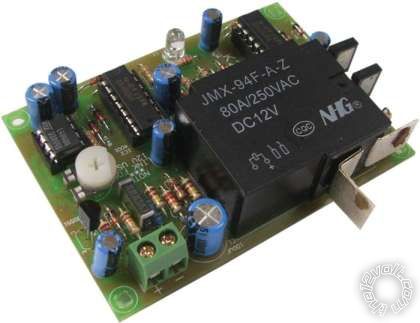 (Ha! Not only is this kit & circuit probably the best I have seen - and much cheaper than alternatives - the kit itself is almost cheaper than an 80A relay. (Ok... maybe double, but hopefully you know what I mean.) But be aware this picture is the kit AFTER you construct it, and no enclosure is included.)
You could use a push button to toggle the Oatley latching relay. I'm not sure if it would need some contact de-bounce (RC filter etc).
But, you'd have to devise some way of knowing which position it's in, and to place it in the desired state when shut off.
The Oatley under/over-voltage (aka Dual Battery) kit K227 does all that automatically and will turn the relay off if power is disconnected.
Although I initially ran the Oatley K227 up front to connect my aux battery, I later changed to the charge-lamp circuit. (In part so I could manually reconnect for jump starting; in part because I never quite finished its enclosure before pressure cleaning the engine bay. The rear "low voltage disconnect" K227 was housed in an IP65 or similar enclosure.)
This morning I posted a similar type of implementation in using relays for auto on solutions (page 2). See if that helps.
[TIP - images with too-long filnemes will not post!]
And Jimmy is correct with his comments etc.
Remember that a vehicle's charging system is designed as a constant-voltage system to charge and maintain a battery. Hence why their settings may vary from a float voltage of 13.8V to the max long-term charging voltage of 14.4V.
Most automotive 12V equipment is rated at 13.8V (for power consumption etc) but is (or should be!!) designed to handle a reasonable time at 16V.
Exceeding 16V can cause damage. (Spikes etc may be over 200V, but they are of short duration and are a separate consideration.)
But in essence, as long as the battery gets its required voltage range (13.8 to 14.4V), and the load is within its limits, anything goes.
Hence the different techniques such as running driving lights etc direct from a higher than 14.4V alternator output whilst limiting the battery to 14.4V. (Eg, maybe dropping diodes or resistors, or the wiring & fuse losses from the alternator to the battery. In old days they used ammeters but they have now been recognised for being as useless as they were then too.)
I did mention somewhere recently of diode and variable-resistor circuits in the alternator (regulator's) sense line to boost the alternator's output voltage. (Maybe earlier in here?)
The charging voltages etc for batteries should vary with their temperature. Cars etc are usually not such a problem because batteries will be at higher temps (engine bay or boot).
But trucks & motorbikes may have exposed batteries. I'd suspect snow machines to have their batteries enclosed and close to the engine.
Fussy systems have temp sensors on their batteries and adjust the charge to suit.
Many alternators have internal temp sensors - they assume the battery is at a similar temperature. (Alternators may also have charging profiles like starting with 14.4V or higher and then dropping to 13.8 once charged.)
And of course we all know that once the battery is charged, there is no battery current flow (excluding instantaneous load changes, and the battery's normal "float current").
Posted By: two12
Date Posted: December 15, 2009 at 9:17 PM
Split Charge Diodes are dated and do not work properly! https://www.smartgauge.co.uk/diodes.html
so they say..
heres a couple of different types of systems:
https://www.smartgauge.co.uk/smartbank.html
https://www.powerstream.com/battery-isolator.htm
Im still undecided as to whats the best way but my set up is a bit more complicated with more than two batteries and more than two charge sources.
just thought I would add those on-topic links but youll have to cut and paste them as I dont have javascripting enabled and this forum requires it for hotlinking.
I like oldsparks suggestion for a standard two battery system.
katman wrote:
I made a dual battery charging system for my motorcycles and scooters so I never have to worry about the start battery failing due to accessory power draw. I use the Odessey PC-680 (AGM Type Battery) as the aux. or House battery. Used a system designed for boating from BEP Marine that incorporates three switches and a VOLTAGE SENCING RELAY to charge the Aux. / House battery when the alternator is putting out 13.8 volts or better. That way my start battery is always charged up first.
I mounted the battery and charging system in a UM-1 size battery box commonly used in trolling motor applications for fishing boats. Used a quick disconnect plug (50 amp) between the start battery and the dual battery charging system in the battery box so I can move it between my vehicles. I'm making a fuse box that incorporates quick disconnect harness from DEL CITY ELECTRIC SUPPLY (toll free: 800-654-4757) which has 3 ea 12ga wires and 5 ea. 16 ga. wires. A harness with matching quick disconnect plug delivers fused circuits to the front and another one delivers fused power to the rear of the bikes and scooters.
The Odessey PC 680 is a dual purpose battery (deep cycle and starting) that will turn over an eight cyl. engine. The control switches have a series parallel switch that will help start the engine using both batteries in an emergency. There is a switch for each of the batteries. On most vehicles you wire the dual charging system using the output of the charging system so the START battery switch must remain ON. The Aux. / House battery power can control all your accessories with the House Battery Switch. The dual battery charging system runs about $150 on line the Odessey PC-680 runs about $110 delivered. I photocopied the instructions and laminated them to keep a copy in the battery box JUST in case.
I am an experienced electrician so the design and installation work wasn't to bad. The average guy could have a difficult time making a system like this work. The box is mounted to the floor of my scooters (have 3 of the same scooter which have 400 watt alternators in it's 250 c.c. engine.)
hey katman! any photos of your set-up? are you using a big car battery on a bike? I have a couple of multisport Hondas that I'd like to have extra power onboard. got anymore info?
thanks
Posted By: oldspark
Date Posted: December 15, 2009 at 10:04 PM
Posted By: katman
Date Posted: December 15, 2009 at 10:05 PM
I'll try to locate the photos. It's an Odyssey PC-680 battery inside of a UM-1 battery box (trolling motor size battery for a fishing boat) the dual battery charging system by BEP is mounted inside the box also. The handles of the switches poke through the side of the box. I have a fuse block by Blue Sea on the top of the box. The main battery is connected through a 50 amp quick disconnect.
Since I have three scooters I made the system transferable between them. Plan on getting a used Honda Element or Scion Xb some day. Will make it compatibale also. I can run aux. lighting and audio equipment from the aux. battery. That way my start battery is always charged full. Also in the plan is a capacitor big enough to fire up the HID ballasts in the aux. lighting system. That's why I wanted to incorporate a latching relay for when I shut down engine and restart after firing it back up.
-------------
"All paid jobs absorb and degrade the mind."
Aristotle
Posted By: katman
Date Posted: December 15, 2009 at 10:17 PM
I have to figure which wire is the B+ from the alternator on my Honda PS-250 scooter. The schematic is not that clear which one actually charges the battery. It shows the + battery lead as a start cable not the B+.
Any comments appreciated.
oldspark wrote:
And since I finally posted a diagram for a charging second battery using my aforementioned method, here is the link to the thread started my some clever dude..... trailor alarm wiring
-------------
"All paid jobs absorb and degrade the mind."
Aristotle
Posted By: berzina123
Date Posted: December 16, 2009 at 1:08 AM
-------------
Posted By: oldspark
Date Posted: December 16, 2009 at 3:45 AM
If the alternator is a rotor controlled unit, then there should only be one thick output wire. (Up to maybe 12G - 14G cable (40A - 30A).)
If it's a permanent magnet, aka "stator" system (thanks for the education BigTime77) as used on many marine motors, my 1972 Ducati and other simple/primitive machines, it may have a 2-phase output or split outputs - eg, one for "non critical" lights, the other for battery else ignition etc.
But the system you described earlier that senses charging (ie, above 13V or 13.5V etc) is the substitute for an alternator-regulator's D+ or L charge lamp output. (This is what BigTime77 would have to use for his marine outboard - there is no charge lamp nor regulator per se.)
The K227 voltage sensor I pictured above from Oatley Electronics does the same (see oatleyelectronics.com products_id=270).
The K227 uses an 80A latching relay. (Be aware that it is a kit - you have to assemble it.)
My wiring in trailor alarm wiring uses a charge lamp circuit. But that Aux-battery relay could instead be connected to the output of the K227 (latching relay) or any other "charge sensing" circuit. (Over-voltage switches can be made with an OPAmp, or a Zenor diode and transitor etc, probably even a Zenor and an optic switch.)
As Berzina suggested, an isolation switch is best. Having two paralleled batteries is useless if the second battery is to guard against a flat first.
But all this trouble for a scooter?
I used to push-start my GPz900 and GT750 when they were dead (not that the Duc GT750 had a starter motor, but it was harder to push start - the rear wheel would usually lock up!)
Then there was always the "flick rear wheel in center-stand" option, but that was only used with its essential "get hands out of spokes quickly" if the tyre couldn't be used.
(And finally the "fitter girlfriend" option. But these days I'm more realistic.)
BTW - other than getting too hot, the actual wire gauge from the charger may not be that important depending on where the voltage is sensed, and what limits the charger's output power.
The alternator/stator may put out 17.4V with a 3V cable drop to yield 14.4V at the battery. In many system, so what? Big deal!
(This is more obvious in permanent magnet systems where the excess voltage is shunted before the battery & loads.)
Posted By: katman
Date Posted: December 16, 2009 at 7:57 AM
The charging system is a 3 phase alternator through a rectifier and regulator. The main fuse for the system is 30 A. The output of the system is a bit higher but they place a 30A fuse so I kept with that size for my aux. system.
The use of the second battery is to accomodate the load of my lighting and audio systems. Gives the start battery a better chance of remaining viable when needed. I have HID driving light, an HID Fog light, aux. turning lights, 550 watt amplifier driving 4 speakers and a sub-woofer. It's quite a bit for an 11 ampere hour main battery so I added the Odyssey PC-680 to handle the lighting and audio loads.
-------------
"All paid jobs absorb and degrade the mind."
Aristotle
Posted By: oldspark
Date Posted: December 16, 2009 at 10:14 AM
Curiosity only - although you say the alternator's 3-phase output is "through a rectifier and regulator", I presume you mean it is rotor controlled regulation - or is it a stator system where the regulator is a heavy-duty dump or pass system?
And some comments on 2.12's earlier references:
two12] wrote:
plit Charge Diodes are dated and do not work properly! https://www.smartgauge.co.uk/diodes.html
The problem of not sensing the correct voltage is easily overcome except with D+ alternators (with charge light only connections).
For 3-wire alternators, merely connect the Sense wire to the relevant battery's +12V.
For 2-wire alternators, the ignition merely energises a relay that connects the relevant battery's +12V to the alternator's Ig (or S) terminal.
And in both cases, hope sensed-battery's Split Charge diode doesn't go open circuit thereby cooking the other batteries!!
Not that diodes are a good way to go anyhow - it might be simple, but it isn't clever for a several reasons - most of which have been covered.
And with a charge light or similar controlled relay, there is negligible voltage drop; it present full voltage to all batteries; uses commonly available relays and is probably cheaper then high-power diodes.
two12] wrote:
heres a couple of different types of systems:
https://www.smartgauge.co.uk/smartbank.html
https://www.powerstream.com/battery-isolator.htm
Im still undecided as to whats the best way but my set up is a bit more complicated with more than two batteries and more than two charge sources.
The SmartBank seems nothing more than the two systems I've discussed.
It does not do any current limiting, nor can it individually regulate its paralleled batteries.
The SmartBank has an optional flash (looking) voltmeter.
I just mounted a $20 LCD voltmeter in my dash instead so I know if I'm over or undercharging, or my battery is dying.
And I'm happy enough with the alternator's charge lamp control of the Aux battery relay. (I too will be connecting several batteries like that - each with its own relay from the alternator.)
For my battery loads like fridges etc, I'm happy enough with the trimpot setting of the K227 and its designed hysteresis and time delays.
As to any delays before connecting auxiliary batteries, as I said, I cannot see the point. If I did, I'd probably add a timer, else maybe a manual override.
I love the PowerStream's "state-of-the art microprocessor"! Is it digital? If so, I'd be very worried! If it's an analog computer - ie, op-amp, comparator, zenor diode etc, then ignore that uPC crap.
It's not much different to the K227 kit, nor my "simple relay" (though mine stays on whilst the alternator signals that it is charging).
The K227 doesn't have a manual connection for "jump starting" (maybe it can be modified?), and my relay system just needs a switch with some OR-ing diodes (that's the full-blown diagram.)
Although in both cases, I'd probably use a separate relay rated for staring (which I have - old type solenoids with manual activation as backup!)
Not that I mean to poo poo good products. But if they don't serve a reasonable purpose, why use them? (Bling & status exempted.)
I've certainly seen many costly products that serve little purpose - in some cases they may impair functionality.
With the above I see little more than a switch with potential for voltage averaging. There is no battery monitoring (meaning alarms or condition reports), no active equalisation, not even a separation of paralleled batteries (which I dislike unless adequately monitored).
As to 2 charge sources, the simplest is isolation between the two, though all batteries & circuit can be commoned when charging off ONE system only. (EG - a recent standard system with additional 250A alternator & 2 extra batteries - still just a normal relay etc.)
Posted By: katman
Date Posted: December 16, 2009 at 3:35 PM
I believe (But not sure) the system is a heavy duty dump. No idea where I might have read that so I'm just guessing at this point. The dual charging system I have sences the B+ and switches the relay to charge both batteries. I wanted to connect it the way the instructions set it up. IT can also use both batteries to start the engine in an emergency. "Kat - it sounds like you do not have a problem. You know which is your alternator output. |
-------------
"All paid jobs absorb and degrade the mind."
Aristotle
Posted By: el ranchero
Date Posted: December 16, 2009 at 5:17 PM
there is a module u need to use to separate both batteries from the alternator, go to your auto parts ask them what u need to hook up a second battery to your car, i forgot the name of the thing, but u cant hook up the batteries together, this will damge your regulator.
-------------
rocker
Posted By: oldspark
Date Posted: December 16, 2009 at 5:57 PM
Hence the "universal" voltage sensing circuit is required.
But your "alternator" should still only have one output.
If not, what is the other output for? (Where to? What power? Or is it the rotor field or battery "Sense" wire.)
I would be inclined to use the original battery's +12V as the connection point since it solves any issues. IE - you have that battery's charging voltage to the second battery; whether the alternator puts out a much higher voltage is of no consequence.
Else - what point am I missing? (Not the desired AGM charge characteristic?)
Posted By: katman
Date Posted: December 16, 2009 at 6:14 PM
I was thinking the difference between connecting to the 12V+ of the main battery would not take advantage of the Voltage Sencing Rely of the dual battery charging system instead of via the B+ of the charging system.
-------------
"All paid jobs absorb and degrade the mind."
Aristotle
Posted By: two12
Date Posted: December 16, 2009 at 6:22 PM
one of my old bikes has a 6volt system. Id like to learn how to have a dual battery set up on it with the secondary being 12volt. I wonder if thats possible without rewiring the stator?
mabey with a step-up transformer? ahhh.. too many other projects at the moment.
oldspark, thats some good info! thanks but ya kinda got too far out on the trailer wiring thread and I want to stay on topic there right now. (one step at a time)
would your example for charging two batteries work for three or more batteries simoultaneously with a one wire altenator (GM)?
Posted By: katman
Date Posted: December 16, 2009 at 7:07 PM
-------------
"All paid jobs absorb and degrade the mind."
Aristotle
Posted By: two12
Date Posted: December 16, 2009 at 7:22 PM
katman wrote:
I mounted the battery and charging system in a UM-1 size battery box commonly used in trolling motor applications for fishing boats.
Posted By: oldspark
Date Posted: December 16, 2009 at 7:25 PM
katman wrote:
I was thinking the difference between connecting to the 12V+ of the main battery would not take advantage of the Voltage Sencing Rely of the dual battery charging system instead of via the B+ of the charging system.
Nope. It is the battery voltage sensing which is the key - not the B+.
As I indicated, they should be much the same.
But if B+ is 20V whilst at the battery it is 13.8V-14.4V, then you want the battery voltage don't you?
Remember that all vehicle charging systems are geared to suit the battery (voltages). (Excluding competitive vehicles & audio systems etc that may be geared for brightest lights or highest power etc.)
two12] wrote:
.. a 6volt system .... a dual battery set up on it with the secondary being 12volt .... without rewiring the stator?
Can be done but "impractical" (two DC-DC converters etc.)
Most 6V vehicles get rewired for 12V. Or converters for specifics like GPS, audio etc.
"too far out on the trailer wiring thread"??? Do you mean I pointed out some functionality issues (with the alarms)?
Tee-hee. Alas the importance of brainstorming, a bouncing-wall etc. The obvious is only obvious is retrospect. Trust me - I have been bounced a lot! (If only modern designs were!!)
But as always - an idea, a proposal, SWOT, improvement, revisit the "aim" (not the solution!), research, review, design, rest, review, ask others (especially stoners), etc etc.
Else there is the good old suck-it&see approach if you have the money and are prepared to risk future time wastage.
BTW - nothing is impossible, it's just that some things are a bit trickier than others, or impracticable.
two12] wrote:
ould your example for charging two batteries work for three or more batteries simoultaneously with a one wire altenator (GM)?
Any aux-battery system can be extended to any number of batteries - whether on relay for parallel batteries (bad) or individual relay per battery or battery groups.
The main difference is that - in particular for the charge-lamp system - the sensing circuit (alternator L or D+) only drive one relay; then that relay drives the others. (Hence f.ex using existing fuel-pump relays (for carby systems) to control the Aux battery relay.
Keep in mind that the D+ system (1-wire charge-Lamp only) AFAIK senses its B+ output. Hence no risk of overcharging (except for alternator faults), but there is no compensation for voltage drops between B+ and the reference battery. (Unless the regulator can be tapped into - but that's what a 3-wire system is for, and a 2-wire system can be wired for (with a relay).)
The beauty of whatever sensing system but with individual relays is that the batteries and their circuits are ONLY connected together whilst charging. (This can be applied to those other systems too.)
At any other time they are totally independent so that a bad circuit will not effect the others - eg, a bad battery will not discharge and ruin other batteries - ie, the parallel-battery problem.
A shortcoming is where a battery is so bad it drags the alternator down and even starts discharging other batteries.
But that's where a voltmeter is best. And maybe temp sensors on each battery.
Otherwise - especially if the battery is an AGM - it will finally melt, explode, flame and burn the installation down.
FYI: On another forum, a "new yellow-top" dude thought he solved his under-charging problems with an alternator upgrade. (He "just didn't get it!"). Several weeks later, the undercharging reappeared. He picked the faulty yellow-top (a collapsed cell or 2) from its radiant heat! Hopefully he then understood why I kept asking for battery voltages and warned him about AGM thermal runaway. It was a nice boot-mounted hot-spot next to the fuel tank etc. Though luckily - as somebody else on that forum explained - the boots in those cars can NEVER burn or explode because its holes and gaps are TOO SMALL for oxygen to get through! Wow, learn something every day eh?
(Don't worry - some guys there were such dorks they preferred a boot fire to an engine-bay fire. It seems they did not know how to extinguish vehicle fires.)
Posted By: katman
Date Posted: December 17, 2009 at 4:45 AM
I thought the B+ had to supply the dual battery charging system in a seperate path? This seems to me to have it available to either battery that would need charged. I'm not an engineer so I'm seeking info here.
With my aux. lighting and sound system load I don't think there is a problem with keeping the batteries charged. The output is much higher than most scooter and motorcycle designs. I would like to have higher output but haven't found a way to improve the OEM one. It's inside the case so fitting a higher output startor would be a problem especially if trying to do it on the cheap!
The 400 watt alternator puts out 15.2 volts which by the time it gets to batteries is right voltage for the AGM batteries. The OEM battery is an AGM type to.
Still any comments are helpful. Thanks for putting time in on my questions.
-------------
"All paid jobs absorb and degrade the mind."
Aristotle
Posted By: oldspark
Date Posted: December 17, 2009 at 6:06 AM
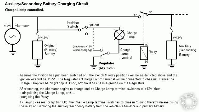
Although shown as charge-light controlled Aux Relay, merely use whatever voltage sensing system output in place of the "Charge Lamp terminal".
As to getting higher alternator output, you probably won't if it's a permanent magnet type (assuming the stator is good). The max power is limited by magnet strength and RPM.
But you can vary the stator's turns ratio and gauge for "optimum" output (at a certain RPM).
In my 120W 2-phase (winding) Ducati system, at low-RPM I would break the centre-tap ground and transfer it to one of the ends, thereby doubling its output voltage, albeit at half the current - but half current was better than nothing. (The Duc would otherwise only "charge" above 2,000 RPM if the headlights were on.)
Mind you, I could have probably improved on their stator winding. I fitted Jap electrics to the rest if the bike so the stator was the only remaining original electrical item.
FYI - Whilst over-voltage to wet lead-acid batteries is tolerable (since they can gas an dissipate heat) - and to a certain extent gel-cels - AGMs are usually very intolerant (no liquid to boil off).
Over-voltage is considered to be above 14.4V (2.4V per cell @ 25 degrees-C aka room temp). However is commented before, some allow higher if their allowable temperature is not exceeded.
(Alas I use older Yuasa & Gates AGMs scavenged from UPS systems and I stick to 2.4V per cell with whatever current limit.)
Posted By: katman
Date Posted: December 17, 2009 at 10:23 AM
I will have to check with Odyssey instruction sheet again. I think my alternator's voltage is okay with their batteries. I was using an LED voltmeter on the dashboard but it fell apart a few weeks back. Going to get a better voltmeter next time.
I have an area away from the original mounting point for the OEM battery. Was thinking of getting a larger battery and place it on the floor of the scooter instead of running dual batteries. Wonder if that would give me a better way to power up my accessories?
-------------
"All paid jobs absorb and degrade the mind."
Aristotle
Posted By: oldspark
Date Posted: December 17, 2009 at 5:10 PM
Info will depend on what brand AND model battery, but Odyssey in one case state:
Cyclic voltage: 14.4V to 15.0V at 25°C (77°F); no current limit
So their warranty is void if the battery temp exceeds 25°C (77°F). I don't know if it is void below 25°C (77°F) (it probably would NOT be voided here in Aus).
Of course, with increasing current (especially near full capacity), the battery temperature increases.
Optima seem a bit more realistic temperature wise, ie:
....14.7 volts. No current limit as long as battery temperature remains below 125°F (51.7°C). When current falls below 1 amp, finish with 2 amp constant current for 1 hour. All limits must be strictly adhered to.
... but that extra boost current at the end is a bummer.
I won't get into a discussion about what people THINK a warranty states as opposed to what a warranty does state, but my experience is that very few claims succeed - users cannot prove their battery remained within tolerance.
Manufacturing faults are honoured, but other failures are touchy. Some manufacturers do readily replace (probably because the purchase price factored in a replacement battery!).
And watch out for those classic "pro-rata" clauses.
katman wrote:
Was thinking of getting a larger battery and place it on the floor of the scooter instead of running dual batteries. Wonder if that would give me a better way to power up my accessories?
Now you are talking about two different aims and designs.
If you want a guaranteed reserve battery using 2 batteries, my diagram (method) above is good.
But it is not for a longer reserve time for accessories - it provides independent reserve times.
If using a bigger battery (whether a bigger mono-block or several smaller batteries) to extend reserve time, the normal "anti-parallel battery" arguments apply.
A single battery is much better unless you have an intelligent battery monitor (ie, that can sense a faulty battery and isolate it, and indicate such faults).
If a "single battery" (whether one or several parallel mono-blocks) but wanting a "guaranteed" reserve for later cranking etc, a low voltage cut-out is required. (Its setting will depend on vehicle, temperature etc.)
And it doesn't matter how big your battery is, it has to be recharged.
If loads are higher than alternator output, the battery will discharge.
Some charge their battery off a domestic or solar supply etc. EG - racers with total-loss systems; 3kW audios with a 2.5kW alternator. (They hope their battery lasts longer than the race or their loudness.)
So hence what is your aim, and what is your situation?
If you ride non-stop with over (say) 400W load, you need to boost your power generation. Alternatively join some auto-service group a or make sure you have cell/phone coverage.
Or you can switch off accessories if the battery gets too low.
(Hence a voltmeter - no complex prediction or averaging of power generation ad consumption, battery age, temperature & capacity - just real-time feed back and control but an allegedly intelligent system.)
A bit off subject, but relevant to the paralleling of batteries - I liked the following Odyssey excerpt:
Even though the drain is low, the effect of a parasitic load on a long-term basis can be significant when the battery supports it for weeks or even months at a time.
They then give a good example, and although it isn't a parallel battery situation, it is an important issue for paralleled batteries.
CarAudio(?) had a good analogy of paralleled batteries at being 2 water tanks of different sizes with different outlet sizes.
Unfortunately it was flawed because - if talking about discharging and charging paralleled batteries - the tanks would be joined at the bottom, hence their level (voltage) will drop at the same rate.
Their rate of current discharge/recharge is irrelevant (except for current constraints - ie, recharging of some AGMs).
But the reasons for NOT paralleling cannot be easily analogised using the water model - that's where experience with the "art and science" of batteries is required.