momentary pb to constant on
Printed From: the12volt.com
Forum Name: General Discussion
Forum Discription: General Mobile Electronics Questions and Answers
URL: https://www.the12volt.com/installbay/forum_posts.asp?tid=126303
Printed Date: May 02, 2024 at 4:57 PM
Topic: momentary pb to constant on
Posted By: sredmyer
Subject: momentary pb to constant on
Date Posted: February 24, 2011 at 9:41 PM
Ok, I am a newbie here and know just enough about electronics and the like to be dangerous so please be easy on me.
Here is my situation; I have a 2008 F350 Super Duty with the factory backup camera. I also added a front camera to aid in nose in parking. I currently am able to display either camera on the factory OEM in dash navigation screen. To choose which is being shown I use this device https://www.qualitymobilevideo.com/LCDQUAD4SW.aspx which is a 4 channel video switcher. The device has a trigger wire for each video input which when pulled to +12 VDC will cause the device to switch the video output to the associated camera input. Currently I control the trigger leads for this device with the factory Aux switches ("Upfitter" switches).
What I would like to do is repurpose an existing steering wheel control button to provide the trigger. I have already modified the steering wheel buttons and clockspring such that an existing rocker button will switch a common between either of two contacts depending on which way the button is pressed. Problem with this is that it only provides a momentary contact while the video switching device requires a constant 12 volts on the trigger lead to cause the camera to be displayed. So what I need to do is to find a circuit to convert this momentary push button into a toggle button. I found this diagram on the relay page which shows using 4 relays to perfom the toggle from momentary.
https://www.the12volt.com/relays/relaydiagram23.html
However as I mentioned I am not very knowledgable about electronics and simply can not follow this diagram to understand how it works...it also seems like it would be a bit noisy with all those relays.
I was hoping someone here could point me to a comercially available solution which would be pretty much plug and play.
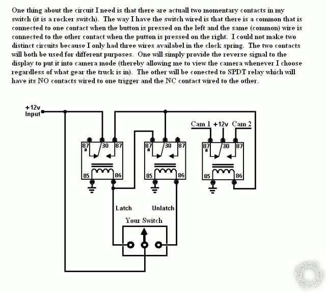
One thing about the circuit I need is that there are actuall two momentary contacts in my switch (it is a rocker switch). The way I have the switch wired is that there is a common that is connected to one contact when the button is pressed on the left and the same (common) wire is connected to the other contact when the putton is pressed on the right. I could not make two distinct circuits because I only had three wires availabel in the clock spring. The two contacts will both be used for different purposes. One will simply provide the reverse signal to the display to put it into camera mode (thereby allowing me to view the camera whenever I choose regardless of what gear the truck is in). The other will be conected to SPDT relay which will have its NO contacts wired to one trigger and the NC contact wired to the other.
Thanks in advance for your help,
Steve
Replies:
Posted By: oldspark
Date Posted: February 25, 2011 at 3:58 PM
I prefer a logic circuit for the toggle function...
I posted one using an inverter somewhere (2 inverters in a hex inverter chip? With resistor(s) and a capacitor?)
Otherwise flip flops etc.
Posted By: sredmyer
Date Posted: February 25, 2011 at 7:57 PM
oldspark wrote:
I prefer a logic circuit for the toggle function...
I posted one using an inverter somewhere (2 inverters in a hex inverter chip? With resistor(s) and a capacitor?)
Otherwise flip flops etc.
Is this the diagram for the inverter circuit you are talking about?
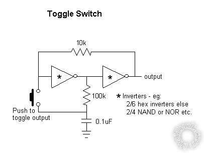
If so, I saw that when trying to find a solution. However I can not see how to make this work for the two buttons I need this for since both must share a common. ------------- Steve
Posted By: oldspark
Date Posted: February 26, 2011 at 2:46 AM
Sorry - I misunderstood. I thought you wanted one button to toggle between the two cameras....
Posted By: howie ll
Date Posted: February 26, 2011 at 12:53 PM
Nice cheap reliable Omron LATCHING relays?
-------------
Amateurs assume, don't test and have problems; pros test first. I am not a free install service.
Read the installation manual, do a search here or online for your vehicle wiring before posting.
Posted By: sredmyer
Date Posted: February 26, 2011 at 2:55 PM
howie ll wrote:
Nice cheap reliable Omron LATCHING relays?
I have looked but have not found any latching relay that does not require reversing the volatage (which I do not have enough wires to do) or some such thing to unlatch them. What I need must switch two different circuits from a single common (can switch either positive or negative).
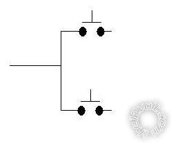
Here is a diagram of what I have.
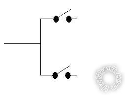
Here is what I need.
Thanks,
Steve ------------- Steve
Posted By: oldspark
Date Posted: February 26, 2011 at 3:00 PM
Two of that latching circuit above!
(Hence using 4 of the 6 hex-packaged inverters. Maybe use the two spares to parallel the output inverter to drive the relays direct (ie, if open collector...)
Posted By: sredmyer
Date Posted: February 26, 2011 at 3:53 PM
oldspark wrote:
Two of that latching circuit above!
(Hence using 4 of the 6 hex-packaged inverters. Maybe use the two spares to parallel the output inverter to drive the relays direct (ie, if open collector...)
Can you do a diagram of how that would go. I can't see any way to do it since both circuits use the same common. ------------- Steve
Posted By: oldspark
Date Posted: February 26, 2011 at 4:19 PM
You mean you cannot rewire the switches to be independent?
Posted By: sredmyer
Date Posted: February 26, 2011 at 9:33 PM
oldspark wrote:
You mean you cannot rewire the switches to be independent?
No I can not. I only have three wires I can use (only spares available in the clockspring) so they must share a common.
Thanks,
Steve ------------- Steve
Posted By: oldspark
Date Posted: February 27, 2011 at 8:10 PM
Maybe this x2...?

Can sort out voltages and switch filtering later...
Posted By: sredmyer
Date Posted: February 28, 2011 at 4:31 PM
WOW!! that is way over my head  . .
I found this device https://www.amazon.com/PAC-TR7-Universal-Trigger-Module/dp/B0002J22BO and think I will give it a try.
Thanks,
Steve ------------- Steve
Posted By: oldspark
Date Posted: February 28, 2011 at 6:05 PM
Yeah - I was brief.
The CD4013 is a 14-pin chip (Integrated Circuit) that costs $1 and contains two "D-type" flip flops which you connect as T-types (ie, Toggle) by interconnection inputs and outputs as above.
The other stuff is an output transistor or buffer in case the 4013 (or whatever chip is chosen - there are others) hasn't the strength to drive your output, and some power-supply protection to limit it to a smooth 15V DC or less...
But that's electronics. A silent $2-$3 solution in a matchbox, but needs a bit of knowledge and soldering.
Posted By: hotwaterwizard
Date Posted: March 30, 2011 at 2:09 AM
 ------------- John DeRosa (Hotwaterwizard)
Stockton California
When in doubt, try it out !
|