Hey guys not sure if anyone has any experience or ideas as this is an uncommon issue in the automotive world. Also this is the 12V forum....lol
I am currently installing 2 group 4D batteries in a mechanic service truck that I wish to be able to connect in series to boost with. My issue is that the truck is 12V and I hope to charge the batteries while driving. I know I can accomplish this with 3 large disconnect switches that would isolate the 12V into each battery respectively and the series connection. I had hoped to make it mostly idiot proof with 1 switch to initiate the 24V boost circuit.
Is this even possible? I have ideas using relays but would need multiple relays and solenoids to accomplish my goal....
Also I'd fab in a bracket and add a 24V alternator for the boost circuit but there's already a VMAC in there and space is very limited!
Thanks again for anyone's thoughts on this.
You can have one switch to control multiple relays.
And those relays need to be at least SPDT, or SPST provided relays on for 12V is acceptable.
IMO the latter is actually a good idea because it provides battery isolation when NOT used for 24V and NOT being charged.
Also because the NC contact of an SPDT relay has a lower current rating then the NO contact (the NO contact being the same as an SPST's contacts - ie, closed when energised), and I suspect you want BIG Amperage relays.
And not that I have a suitable 2 x 24V with 4 x 12V diagram, but I'd start with the fig I posted in
charging two 12v batteries in series tho that uses a DPDT else 2 SPDT relays - or whatever I wrote in the fig's notes if a 'failsafe' setup is required (ie, to ensure a short across a battery never occurs).
POST EDIT - it seems I wasn't notating a
failsafe connection (that was covered but elsewhere) but 'aux' battery isolation in
12V mode when NOT being charged.
Thank you old spark.
I am only intelligent in appearance and I don't understand the fail safe's needed.
The diagram you linked, is, I believe what I need, except I don't understand how the 24V is isolated from the 12V? Shouldn't there be a disconnect or diode etc towards the ign circuit? Sorry I am not smart enough....
Maybe this is more what I am looking for?
LinkNo diode needed just as that
12/24 Volt DC Series Parallel Switch you linked has no diode.
Have a look at my diagram. The relay contacts are shown in 12V mode - ie both batt +12V's joined together and both batt -ve to GND.
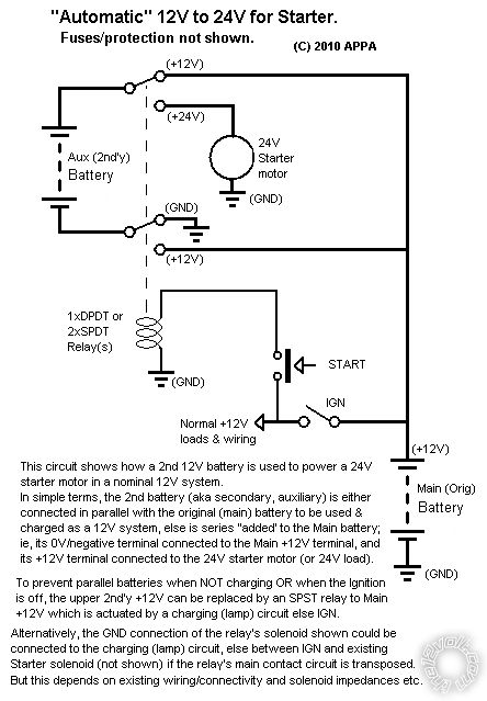
With the relay energised (IGN & Start closed), the top relay arm swings down to the 24V starter motor and the bottom arm reconnects the "upper" battery's -ve to +12V, hence making the upper battery's +ve terminal (12 + 12 =) 24V.
At no time does the
lower 12V part see 24V, it only ever sees the lower battery's 12V.
If however the lower arm connects to +12V BEFORE the upper contact has broken it's upper contact, you then have a short across the upper 12V battery.
That's the failsafe part - if using TWO SPDT relays (or several SPST) instead of a DPDT relay, you must ensure the upper arm breaks from the upper contact before the lower arm makes its lower contact.
Of course all you have to do is pair up 2 batteries in parallel for your Main and Aux/secondary batteries respectively and connect according to that diagram.
However I am so conditioned into NOT having paralleled batteries (except when being used or when being charged) that I automatically think of (automatic) battery isolation and that's what I mention in the diagram's notes.
But that fig was for ONE extra battery added to the Main battery for a 24V starter.
I'd assume your 4 batteries are separate to your main battery, hence for isolation four isolating relays are required else 4 terminals need to be disconnected (IMO after a few or several hours if leaving unused or not charging).