wiring up my hei ’74 401 cherokee
Printed From: the12volt.comForum Name: General Discussion
Forum Discription: General Mobile Electronics Questions and Answers
URL: https://www.the12volt.com/installbay/forum_posts.asp?tid=136473
Printed Date: April 29, 2024 at 9:39 AM
Topic: wiring up my hei ’74 401 cherokee
Posted By: berettajeep
Subject: wiring up my hei ’74 401 cherokee
Date Posted: April 18, 2014 at 4:22 PM
Okay I posted this on other websites but I am not getting much feedback as I would like. I remembered this site (and thought I joined many many moons ago but I guess not...)
I am Dennis. I am working with a 1974 Cherokee 401 stock points, stock alternator (for now), stock wiring (for now)
Searching on line I find numerous ideas and way things are done. I down loaded the factory wiring harness and took it to Staples and had them print it out on 11x17 card stock. I want to be sure what wires to change/ remove/ use before I actually start physically doing it. I will also be replacing fuse block with an EZ-wiring one and upgrading to the cs-144 alternator ( just not at this time)
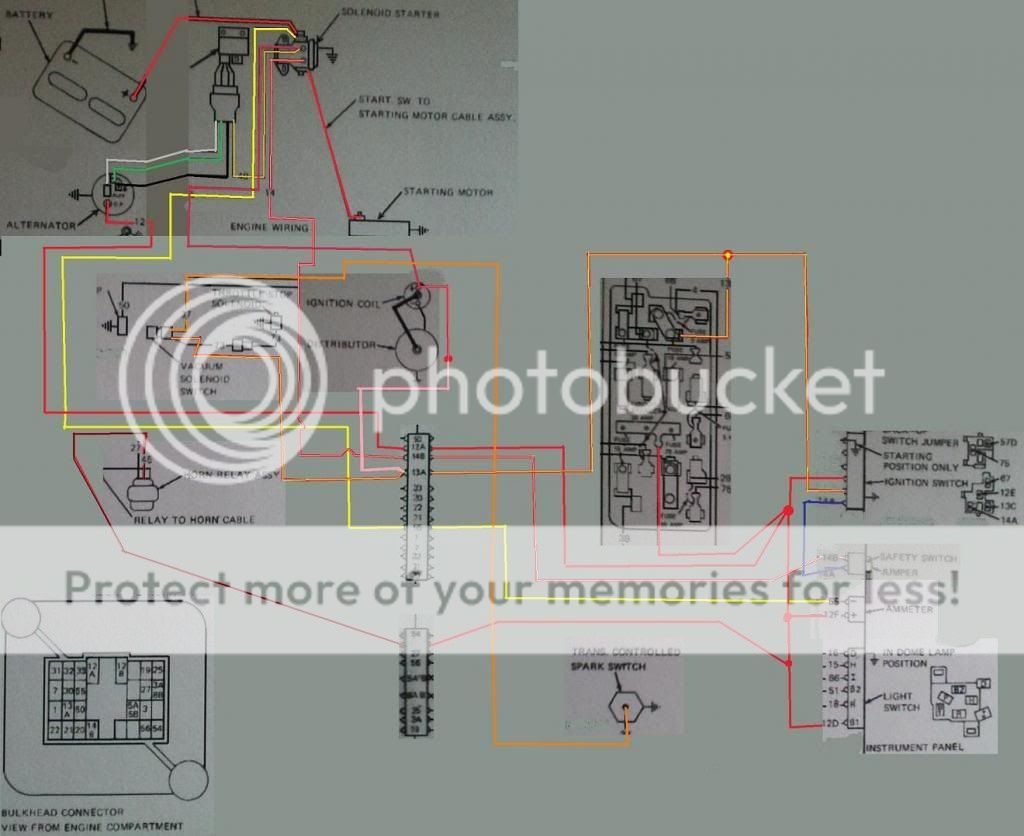
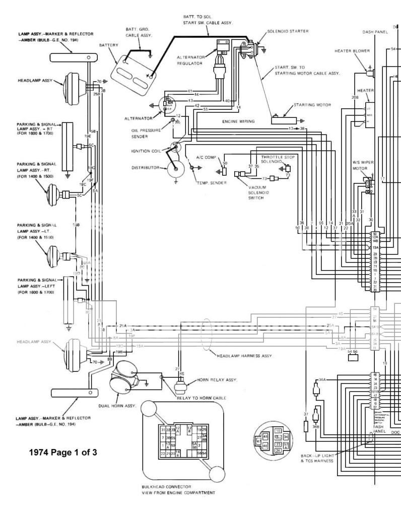
Here is my stock wiring.
Here is what I would do.
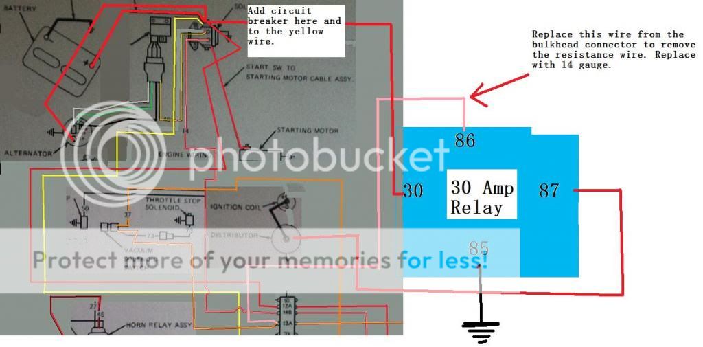
1) Remove the 10 gauge unfused interior feed from the alternator to the starter solenoid and add a 30 amp circuit breaker.
2) Already had a 2 gauge battery cable made, connect from the starter solenoid to alternator.
3) Remove the resistance wire by-pass that goes from the coil to the starter solenoid.
4)Remove the 20 gauge resistance wire from the bulkhead connector and replace the wire with a 14 gauge to feed #86 on the relay.
5)Run a 12 gauge wire from #87 on the relay to my Batt. on the new HEI.
6)Run a 12g wire to a 30 amp circuit breaker then to #30 on the relay.
7) ground #85 to the body.
8) Could I now remove the the 10g yellow wire that goes from the solenoid to the amp* gauge?
*I have already done the volt meter upgrade, is it possible to run that so it is not always on?
Please share opinions. I've been looking at this for days and one day it looks good to go and then another day I think it's totally wrong.
Are there pointless connections I am doing or something I forgot?
Thanks, Dennis
I am Dennis. I am working with a 1974 Cherokee 401 stock points, stock alternator (for now), stock wiring (for now)
Searching on line I find numerous ideas and way things are done. I down loaded the factory wiring harness and took it to Staples and had them print it out on 11x17 card stock. I want to be sure what wires to change/ remove/ use before I actually start physically doing it. I will also be replacing fuse block with an EZ-wiring one and upgrading to the cs-144 alternator ( just not at this time)
Here is my stock wiring.

Here is what I would do.

1) Remove the 10 gauge unfused interior feed from the alternator to the starter solenoid and add a 30 amp circuit breaker.
2) Already had a 2 gauge battery cable made, connect from the starter solenoid to alternator.
3) Remove the resistance wire by-pass that goes from the coil to the starter solenoid.
4)Remove the 20 gauge resistance wire from the bulkhead connector and replace the wire with a 14 gauge to feed #86 on the relay.
5)Run a 12 gauge wire from #87 on the relay to my Batt. on the new HEI.
6)Run a 12g wire to a 30 amp circuit breaker then to #30 on the relay.
7) ground #85 to the body.
8) Could I now remove the the 10g yellow wire that goes from the solenoid to the amp* gauge?
*I have already done the volt meter upgrade, is it possible to run that so it is not always on?
Please share opinions. I've been looking at this for days and one day it looks good to go and then another day I think it's totally wrong.
Are there pointless connections I am doing or something I forgot?
Thanks, Dennis
Replies:
Posted By: oldspark
Date Posted: April 18, 2014 at 7:44 PM
Can you explain what you are trying to do - ie, add or bypass or upgrade...?
Unfortunately I can't save the pics and even if clear enough I don't like working side-on.
Unfortunately I can't save the pics and even if clear enough I don't like working side-on.
Posted By: oldspark
Date Posted: April 18, 2014 at 8:02 PM
PS - if it's to remove the IgCoil ballast aka resistor, simply bridge it (ie - short it out; wire from one end to the other) or remove it and join the 2 ends together, or connect its input (IGN +12V) end (the end NOT connected to the IgCoil) to your HEI +12V input and direct to the IgCoil "+" terminal (which was connected to the other end of the ballast).
The starter wire that was connected to the coil+ and ballast can be left disconnected - just insulate it so it does not connect or short to anything.
I suspect you are fitting a modern or HEI ignition which do not require internally ballasted (+12V) IgCoils nor ballasts fitted for later external-ballast (+8V) IgCoils.
In fact hopefully it will allow - and you will fit - a modern E-core type IgCoil. (Tho I'm using an old "typical" blue Nippon Denso IgCoil since it can cold start my vehicle with a very very flat battery (namely 6V).
Posted By: Ween
Date Posted: April 18, 2014 at 8:15 PM
Hi,
If in the dash harness, the ignition feed at the bulkhead connector is large enough (14 gauge or better), why not use the same gauge lead to feed the HEI? If you have to use a relay, the resistance wire will adequately operate a bosch-type relay with no ill effects. A bosch-type relay is about 160mA, much less than an ignition coil.
For the charge lead with the stock system, the charge current is along the yellow wire. If removed, the battery won't charge. If bypassing the ammeter, the yellow wire would be jumped to the red at the ammeter. Or the alternator output could be connected to the starter solenoid battery junction point. This would be done with your high current (cs144) alternator upgrade, use an adequately sized wire. You could use the yellow wire as a voltage sense lead for the new alternator.
Connect the voltmeter positive to an ignition switch controlled fuse (gauges).
Mark
Posted By: berettajeep
Date Posted: April 18, 2014 at 8:28 PM
oldspark wrote:
Can you explain what you are trying to do - ie, add or bypass or upgrade...?
Unfortunately I can't save the pics and even if clear enough I don't like working side-on.
I fixed the picture. Should be able to click on it to make it bigger.
What I am trying to accomplish is to remove the points system and replace with an HEI distributor. Also upgrade and remove wires I won't need.
Posted By: berettajeep
Date Posted: April 18, 2014 at 8:40 PM
Ween] wrote:
Hi,
If in the dash harness, the ignition feed at the bulkhead connector is large enough (14 gauge or better), why not use the same gauge lead to feed the HEI? If you have to use a relay, the resistance wire will adequately operate a bosch-type relay with no ill effects. A bosch-type relay is about 160mA, much less than an ignition coil.
For the charge lead with the stock system, the charge current is along the yellow wire. If removed, the battery won't charge. If bypassing the ammeter, the yellow wire would be jumped to the red at the ammeter. Or the alternator output could be connected to the starter solenoid battery junction point. This would be done with your high current (cs144) alternator upgrade, use an adequately sized wire. You could use the yellow wire as a voltage sense lead for the new alternator.
Connect the voltmeter positive to an ignition switch controlled fuse (gauges).
Mark
Mark I bypassed the old ammeter by moving the red and yellow wire together. Wanting to be able to see what my charging system is doing I replaced the ammeter with a volt meter. Right now both the yellow and red wires are going to the + side of the volt meter and I grounded the - post on the volt meter. Unfortunately even with the Jeep off, the volt meter shows what voltage the battery has.
I want to move the red wire from the back of the alternator to the ignition side of starter solenoid. Add a #1 battery cable from the starter solenoid to the back of the alternator
I'm not sure if I need to use a relay though, what would you recommend?
Posted By: Ween
Date Posted: April 18, 2014 at 9:01 PM
Shouldn't be too hard to locate a switched power source under the dash.
The alternator output (heavy gauge) wire needs to connect to either the positive battery terminal or the previously mentioned starter solenoid terminal (battery side).
Not familiar with the AMC/Jeep wiring harness, but if the wire is 14 gauge or larger, that should be more than adequate for an HEI ignition system.
The relay adds complexity to the circuit.
Posted By: oldspark
Date Posted: April 18, 2014 at 9:58 PM
Cool... glad I clicked (ie, my PS). Sorry - I'm feeling groggy after some (drug & alcohol free) days away camping.
I endorse what Ween wrote - you should be able to power your HEI from the existing wire to the IgCoil ballast. That's IGN +12V.
Where I thought that wire was too small - or if I thought Ign or HEI noise injected back thru the wire to the IGN switch etc might cause unwanted noise and interference - I'd use the wire to turn on a typical automotive 30A relay (86 with 85 to GND) to connect the HEI +12V and igCoil+ (else igCoil's ballast resistor) to the battery - ie, 30 & 87 - with a suitable fuse (usually at least 15A, maybe 30A - but equal to or less than what current the wire and relay could handle).
You do not want to interrupt the alternator +12V output (usually called B or B+) to the battery +12V since that can cause electrical damage - especially on older alternators with external regulators.
[ Older alternators could go way over +16V without a battery connected. Newer alternators may limit their output to under 16V but without a battery connected there is nothing to filter +12V noise (switching relays, motors, etc) and voltage spikes can damage equipment, and furthermore the engine is likely to stall if there is a step change like flashers or brake lights etc. ]
I often recommend upgrading older external regulated alternators to modern alternators with integral regulators (specifically those with a dedicated "Sense" wire that goes straight to the battery +12V) since they exhibit far superior behaviour and overcome problems that can occur with external voltage regulators (eg, loss of or bad GNDs).
If the old system works then leave it. But when problems appear, IMO forget the common tail-chasing scenario of replacing the regulator, then the alternator, then the regulator again, and then BOTH the alternator & regulator and replace the lot with an all in one modern alternator.
They merely have to physically fit (with aligned belt) and have at least the required output (Amps).
The wiring is usually easy... Upgrade the heavy B/B+ to battery +12V (maybe with a fuse close to the battery +12V which is to protect the battery & cable from a cable short - it rarely protects the alternator). Connect the L (or D+) charge light wire to the existing circuit - eg, into the appropriate pin/terminal of the old requlator's main harness connector. And connect the S (Sense) wire direct to the battery +12V terminal (that can be fused else merely use a thin cable which won't cause damage if it shorts & fuses).
If they also have an I or IGN terminal, that can also probably go to the old regulator's harness connector, or your igCoil +12V (igCoil+) etc - though most alternators are usually only S&L types and no longer use a dedicated I or Ig or IGN +12V signal, else only have the L = charge light known as D+ (but I usually recommend S&L types rather than the D+ only types).
Apologies if that's a lot of detail, but I hope it helps.
If unclear, please ask.
And I'd probably consider your own separate wiring. I haven't been impressed with the wiring of more recent Jeeps and I dread to think of Jeeps that are more than 20 years older....
Posted By: oldspark
Date Posted: April 18, 2014 at 10:08 PM
Some additional stuff.
Ammeters are essentially useless. And certainly those without external shunts - ie, those that drag the (alternator to) battery cable thru the cabin are stupid, and hazardous.
A 3 digit (dash mounted) voltmeter across the battery terminals will tell you all you need to know about your charging system, and probably your battery health too.
My dash voltmeter is connected to batt +12V via a small (1A) relay actuated by IGN +12V. (Tho I have long intended to add a manual switch as well as some hold-on delays to control that relay.)
Hopefully your HEI is a good unit. I recommend reluctor sensors (new generation with single lobes and a single self contained sensor) feeding suitable ignitors.
IMO the best ignition system (ignitor) is CDI tho I ceased building my cheap sequential spark CDI after finding out just how good my 'more modern' 1980's vintage reluctor & ignitor and igCoil was.
PS - bypass the ammeter wiring with the alternator output direct to the battery +12V else the starter-motor's heavy input - or as some vehicles do, to the main fusebox +12V etc.
But IMO alternator direct to battery +12V is best - provided it's easy to do. That should be the shortest run.
Remember that the alternator should be supplying the correct voltage for the battery - ie, not too low, and in general not above 14.4V longterm for a typical flooded/wet cell battery.
Voltage drops along the alternator-battery current path can cause problems tho S-terminal Sensing regulators (alternators) overcome that from the battery's POV, but that may mean higher voltages elsewhere if it's not a direct alt-batt connection.
Posted By: howie ll
Date Posted: April 19, 2014 at 6:31 AM
Don't know if anyone else mentioned this but AFAIK concerned the voltmeter is part, i.e. wired in parallel to the ignition circuit.
Otherwise absolutely agree with everything Oldspark and Ween suggest, also that the ammeter is useless, BTW if you keep it, the ammeter should use 5 gauge or even thicker wiring and be in series from the battery for everything bar starter and alternator leads.
-------------
Amateurs assume, don't test and have problems; pros test first. I am not a free install service.
Read the installation manual, do a search here or online for your vehicle wiring before posting.
Posted By: oldspark
Date Posted: April 19, 2014 at 9:33 AM
Ditto. OEM ammeters only measure what goes in & out of the battery (cranking excluded!!) and not what the alternator puts out, etc. Hence they normally read zero Amps - exclusions being after cranking (replacing lost charge), step changes (till the alternator steps up or down), or alternator shortfalls (idling; excessive loads).
If you connect loads to the battery (like audio, PCs etc), the Amperage means nothing tho battery ground (shunt) ammeters may give valid readings.
An ammeter will not tell you if you are overcharging, undercharging, the battery condition, nor if the alternator isn't quite sufficient.
And tho OEM voltmeters are (usually) wired across ignition, that is usually not an accurate battery voltage (which is what alternator voltage is all about) due to battery to ignition voltage differences which can be 1V or more - and the difference between a 14.4V and 14.5V or 14.6V battery charge voltage can have a significant effect on battery health.
Hence why I say to add one across the battery, else rewire the OEM, and add an IGN controlled relay to disable the voltmeter when IGN is off.
Of course for analog (electro-mechanical) voltmeters, such errors are probably undetectable.
A 3-digit voltmeter is ideal - eg, 12.9V, 26.7V, etc. (4 digit is way to accurate and bobbly for normal use.)
Posted By: Ween
Date Posted: April 19, 2014 at 10:26 AM
When using an analog voltmeter of unknown accuracy, compare its readings to a known to be accurate meter. Do this at various operating conditions of the vehicle. Its easier to detect a change in pointer position than a static pointer position. I.E. Does the pointer deflect as various loads are turned on? This is helpful in determining if various systems are operational.
Posted By: berettajeep
Date Posted: April 19, 2014 at 2:30 PM
Okay that is a lot to take in all at once  I will try to draw up what has been suggested, as that is how I may understand this better. Then it should make sense to me.
For the record and in case it has been missed, I no longer have the ammeter. They became a fire hazard in these old Jeeps as the wires get older and what not. I have replaced it with a volt meter.
Thank you very much for taking your time and helping me with this.
I will try to draw up what has been suggested, as that is how I may understand this better. Then it should make sense to me.
For the record and in case it has been missed, I no longer have the ammeter. They became a fire hazard in these old Jeeps as the wires get older and what not. I have replaced it with a volt meter.
Thank you very much for taking your time and helping me with this.
Posted By: oldspark
Date Posted: April 19, 2014 at 7:54 PM
In return, thanks! for your fire hazard comment.
That's why automotive modern ammeters are shunts - ie, a calibrated voltmeter that measures the voltage drop across an in-line resistor (I=V/R) - so that the heavy current (path) is not routed thru the cabin - only a couple of mA rated wires for the voltmeter. But as I said, ammeters are usually only for experimentations etc, and I am still to find out their success in certain modern vehicles.
My 1960s vehicle had the same as yours - battery+ terminal in to the gauge and back out to the car +12V feed (alternator output etc) - NO fuse.
The only thing worse is competitive vehicles that have +12V cabin and maybe rear corner mounted battery isolation switches... they are sized to carry cranking currents rather than the usual 30A or 60A max of cabin ammeters. (I laugh when I see such implementations flame!)
(Reconsidering - one thing worse is combined engine kill & isolation switches! I look forward to lawsuits.)
Anyhow, lots of extra information.
But your basic OP answer is (IMO) simple - namely use the original IGN +12V igCoil feed to power your HEI and igCoil, else use it to energise a relay to power them - eg, via 20A-30A fuse with (say) 30A cable direct from batt+.
Ask if you need more info on interpreting a/the voltmeter, or anything else.
Posted By: berettajeep
Date Posted: April 19, 2014 at 8:37 PM
That is what I forgot to mention, The HEI I will be using is an internal coil ( Think G.M.) not the external that the factory was.
Posted By: oldspark
Date Posted: April 19, 2014 at 9:21 PM
I'm not familiar with it. I am familiar with some of the Delco/Delphi systems but they are typical reluctor & ignitor with external igCoil(s) (tho their ignitors are ECU interactive (viz HEI-8 or whatever they were), and their reluctor generation seemed to lag a few years).
Try first using the original IGN +12V wire to the ballast end of the igCoil.
If that wire gets warm or hot (compared to its surroundings), use the relay.
Try first using the original IGN +12V wire to the ballast end of the igCoil.
If that wire gets warm or hot (compared to its surroundings), use the relay.
Posted By: Ween
Date Posted: April 19, 2014 at 9:32 PM
Integral coil HEI distributors typically use a minimum of 14 gauge wire for their power wire.
Posted By: howie ll
Date Posted: April 20, 2014 at 1:05 AM
Sorry lads but you brought back memories from around the 1970s of rewiring battery to gauge looms on London Taxis and Ford Capris.
You know what they had in common don't you.
The taxis were a joy, 100,000 a year and covered in caked on diesel etc. etc.
-------------
Amateurs assume, don't test and have problems; pros test first. I am not a free install service.
Read the installation manual, do a search here or online for your vehicle wiring before posting.
Posted By: berettajeep
Date Posted: April 21, 2014 at 8:41 PM
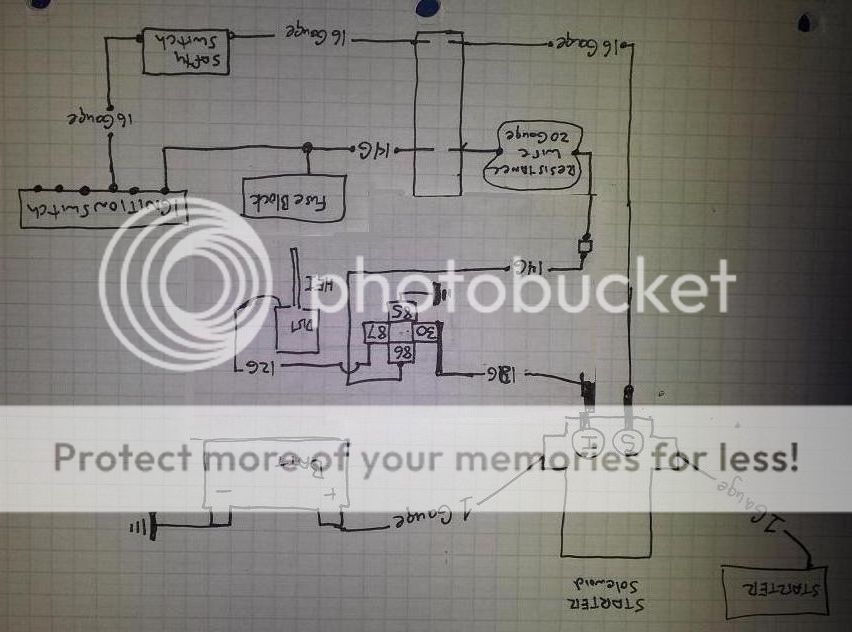
Okay this is what I came up with, with what I understand. 
Basic drawing of what I have.

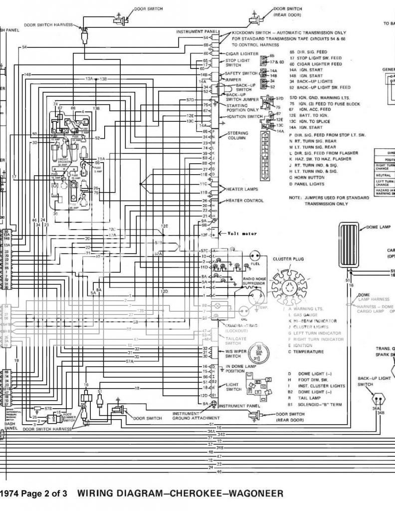
The "S" terminal on the starter solenoid has a 16 gauge wire going through the bulkhead connector through the safety switch into the ignition switch.
Out of the ignition switch is a 14 gauge wire that splits into the fuse box and goes through the bulkhead connector where it becomes a 20 gauge resistance wire, then becomes a 14 gauge wire again then connects to the coil (+).
The "I" terminal is a 14 gauge wire that goes directly to the coil (+).
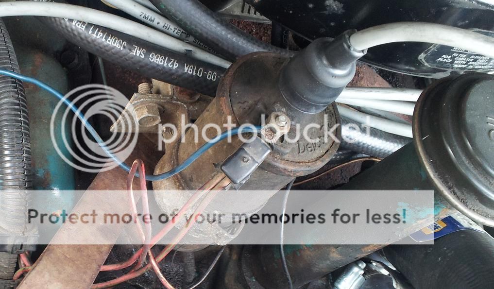
Both wires connected to the coil (+). (Side note, do you like the wrapped around blue wire on the coil that goes through the firewall for the A/C? Previous owner or whoever did this. This is why I ask questions. I really hate wiring hacks.)
At first I thought I could do this:
But looking at it more and searching around, The "I" terminal only sends 12 volts momentarily. So I did this:

This way it has full voltage going to the relay but only activated when I turn the key.
Would I want to put a fusible link or circuit breaker "I" terminal and #30 on the relay?
From the relay to the distributor is a 12 gauge wire.
Or am I still not getting it?
Basic drawing of what I have.

The "S" terminal on the starter solenoid has a 16 gauge wire going through the bulkhead connector through the safety switch into the ignition switch.
Out of the ignition switch is a 14 gauge wire that splits into the fuse box and goes through the bulkhead connector where it becomes a 20 gauge resistance wire, then becomes a 14 gauge wire again then connects to the coil (+).
The "I" terminal is a 14 gauge wire that goes directly to the coil (+).
Both wires connected to the coil (+). (Side note, do you like the wrapped around blue wire on the coil that goes through the firewall for the A/C? Previous owner or whoever did this. This is why I ask questions. I really hate wiring hacks.)

At first I thought I could do this:

But looking at it more and searching around, The "I" terminal only sends 12 volts momentarily. So I did this:

This way it has full voltage going to the relay but only activated when I turn the key.
Would I want to put a fusible link or circuit breaker "I" terminal and #30 on the relay?
From the relay to the distributor is a 12 gauge wire.
Or am I still not getting it?
Posted By: oldspark
Date Posted: April 22, 2014 at 12:50 PM
The last fig looks ok.
So instead of powering the igCoil, you energise the relay (86). Good idea! That overcomes the resistive wire which I assume is in lieu of a ballast resistor to drop voltage to an 8V "external resistor" type igCoil.
The relay connects battery +12V #30 to #87 thus powering the HEI and its igCoil.
Although you could put a fuse near the starter solenoid to #30, but the original did not have it and most igCoils don't have fuses for reliability and safety reasons - you really do not want to spark due to an aging fuse or extra connections.
IMO it's better to rely on physical protection - make sure the connections and wiring is secure and well insulated.
I assume the HEI needs no ballast resistor... It either has its own else like most modern ignitors, has current limiting so that any igCoil can be used.
I reckon that should work well.
The only tip I'd give is to keep your original dizzy & igCoil (with ballast) with you in case - or when - the HEI or igCoil fails. If there is no ballast because that's done by the resistive wiring, then connect the relay's #86 to the igCoil when needed. With a ballast, connect the relay output 87 thru the ballast to igCoil+ (with igCoil- going to the points, and tacho if fitted).
Good luck!
PS - BTW, I suspect the solenoid's "I" is only momentarily +12V during cranking - ie, it's the ballast/resistive-wire bypass to give full +12V to the igCoil during cranking (which is not needed for HEI etc).
And yes, I like the wire-wrapped +12V connection. Of course experienced quality practitioners like us would NEVER do anything like that... But the ones on my vehicle are still working fine.
 (And they'll probably continue to work unless I decide to join them properly. But if it works, leave it alone - I'm certain that saying was invented from the times I finally cleaned up rats nests (or built proper PC boards for components) only to find total failure of the circuits involved.
  )
)
So instead of powering the igCoil, you energise the relay (86). Good idea! That overcomes the resistive wire which I assume is in lieu of a ballast resistor to drop voltage to an 8V "external resistor" type igCoil.
The relay connects battery +12V #30 to #87 thus powering the HEI and its igCoil.
Although you could put a fuse near the starter solenoid to #30, but the original did not have it and most igCoils don't have fuses for reliability and safety reasons - you really do not want to spark due to an aging fuse or extra connections.
IMO it's better to rely on physical protection - make sure the connections and wiring is secure and well insulated.
I assume the HEI needs no ballast resistor... It either has its own else like most modern ignitors, has current limiting so that any igCoil can be used.
I reckon that should work well.
The only tip I'd give is to keep your original dizzy & igCoil (with ballast) with you in case - or when - the HEI or igCoil fails. If there is no ballast because that's done by the resistive wiring, then connect the relay's #86 to the igCoil when needed. With a ballast, connect the relay output 87 thru the ballast to igCoil+ (with igCoil- going to the points, and tacho if fitted).
Good luck!
PS - BTW, I suspect the solenoid's "I" is only momentarily +12V during cranking - ie, it's the ballast/resistive-wire bypass to give full +12V to the igCoil during cranking (which is not needed for HEI etc).
And yes, I like the wire-wrapped +12V connection. Of course experienced quality practitioners like us would NEVER do anything like that... But the ones on my vehicle are still working fine.
(And they'll probably continue to work unless I decide to join them properly. But if it works, leave it alone - I'm certain that saying was invented from the times I finally cleaned up rats nests (or built proper PC boards for components) only to find total failure of the circuits involved. )Posted By: berettajeep
Date Posted: April 28, 2014 at 10:53 PM
Well I messed up somewhere....
Hooked up everything and tried starting it but it did not start. Checked everything, made sure I was on #1 TDC and everything, still only turns over but does not fire.
Then I noticed one of the posts ( "S" or "I", I don't remember for sure) on my starter solenoid was loose, so I tightened it. After that I tried to start again. Still did not start but after I put the Key in the off position, the motor kept turning over very slowly.
So I quickly remove the negative battery cable and use my volt meter and sure enough I have 12 volts coming out of every post on the starter solenoid.
Not cool.
Thinking maybe I messed up something internally on the solenoid when I tightened up the post, so I switched it out with another I have. Still getting 12 volts out every post.
So back to the drawing board. It is something so simple that I am not seeing or something I messed up. Need to step back for a moment to re think.
Posted By: berettajeep
Date Posted: April 30, 2014 at 10:50 PM
Okay here is the actual wiring diagram, not my drawing
Here is what it is originally:
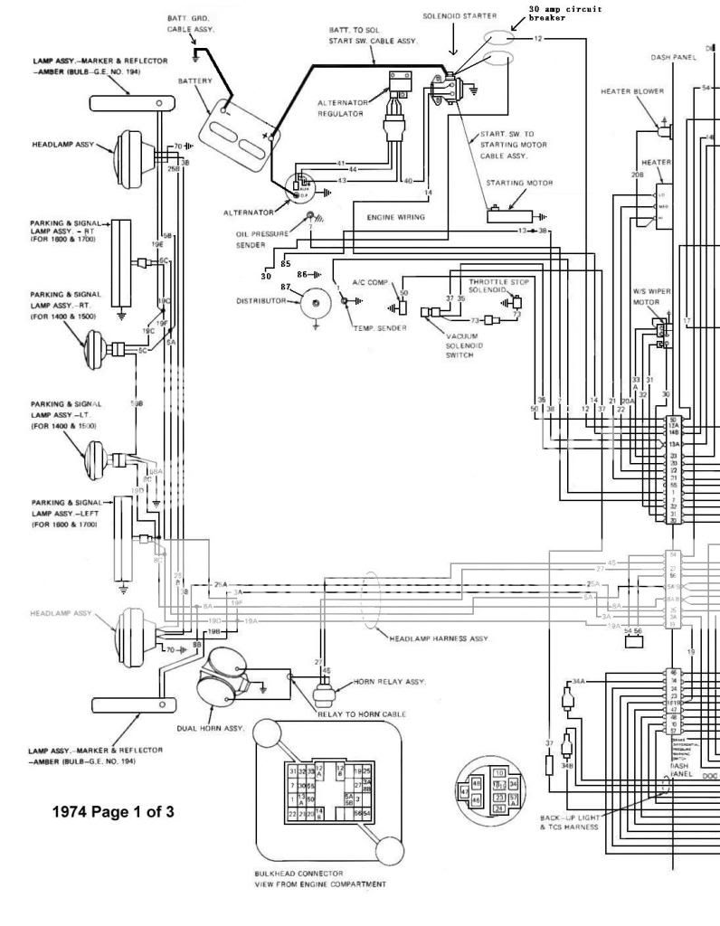
Here is what I did:
Original:

What I did.
I changed the wiring diagram to reflect what I did to my Jeep.
To recap:
#12 wire originally went to the back of the alternator, it now goes to a circuit breaker on the battery side of the starter solenoid.
A 1 gauge battery cable now goes from the back of the alternator to the battery.
Wire #55 I completely removed. It went from the battery side on the solenoid to the amp gauge. I removed the amp gauge,it is now a volt meter. Wire #12 connects to the positive and the negative is grounded on the volt meter.
I removed #42 wire that went from the "S" on the starter solenoid to the positive side of the coil. ( Coil was removed )
From the bulkhead connector #13A, The wire splits and one becomes #38 which is a resistance wire (20 gauge). It then goes back into a 14 gauge (Wire #13) which I connected to #85 on a 30 amp relay. I have a 12 gauge wire coming from the battery side of the starter solenoid to a circuit breaker to #30 on the relay. #86 is grounded and # 87 goes to the batt. side of the Distributor (12 gauge wire)
All 4 battery cables are 1 gauge. Negative cable grounds the the motor and also the body.
With only the positive battery cable connected to the battery, I use my volt meter
My problem is the starter solenoid has 12 volts coming out all posts. ("S"; "I", and starter side)
I am requesting help, because I can't see why this is happening ( I am an amateur though.)
Here is what it is originally:

Here is what I did:

Original:

What I did.

I changed the wiring diagram to reflect what I did to my Jeep.
To recap:
#12 wire originally went to the back of the alternator, it now goes to a circuit breaker on the battery side of the starter solenoid.
A 1 gauge battery cable now goes from the back of the alternator to the battery.
Wire #55 I completely removed. It went from the battery side on the solenoid to the amp gauge. I removed the amp gauge,it is now a volt meter. Wire #12 connects to the positive and the negative is grounded on the volt meter.
I removed #42 wire that went from the "S" on the starter solenoid to the positive side of the coil. ( Coil was removed )
From the bulkhead connector #13A, The wire splits and one becomes #38 which is a resistance wire (20 gauge). It then goes back into a 14 gauge (Wire #13) which I connected to #85 on a 30 amp relay. I have a 12 gauge wire coming from the battery side of the starter solenoid to a circuit breaker to #30 on the relay. #86 is grounded and # 87 goes to the batt. side of the Distributor (12 gauge wire)
All 4 battery cables are 1 gauge. Negative cable grounds the the motor and also the body.
With only the positive battery cable connected to the battery, I use my volt meter
My problem is the starter solenoid has 12 volts coming out all posts. ("S"; "I", and starter side)
I am requesting help, because I can't see why this is happening ( I am an amateur though.)
Posted By: berettajeep
Date Posted: April 30, 2014 at 10:51 PM
You can click on the pictures to enlarge them.
Posted By: oldspark
Date Posted: May 02, 2014 at 12:25 AM
All looks ok except for your 30A CB on #12. Since #12 carries current for every load on the vehicle (except the starter-motor, 30A isn't enough. Plus it's dangerous - it'll take out your lights as well...
Leave it as it was - no electrical protection.
I assume the HEI relay clicks when you turn on the IGN?
I might find something else later, but let's eliminate the tripping of the #12 30A breaker.
Leave it as it was - no electrical protection.
I assume the HEI relay clicks when you turn on the IGN?
I might find something else later, but let's eliminate the tripping of the #12 30A breaker.
Posted By: berettajeep
Date Posted: May 02, 2014 at 1:00 AM
oldspark wrote:
All looks ok except for your 30A CB on #12. Since #12 carries current for every load on the vehicle (except the starter-motor, 30A isn't enough. Plus it's dangerous - it'll take out your lights as well...
Leave it as it was - no electrical protection.
I assume the HEI relay clicks when you turn on the IGN?
I might find something else later, but let's eliminate the tripping of the #12 30A breaker.
I am not sure if it clicks. The problem right now is I am getting 12 volts out of every post on the starter solenoid.
Things I did today:
I removed the aftermarket radio. Previous owner wired it with two fuses in a row.....Don't ask I have no idea why.
I removed the electric brake for a trailer.
Also removed a few other wires that were spliced into the factory harness.
Still getting 12 volts out of all the starter solenoid posts.
I disconnected everything from the starter solenoid except the positive cable from the battery, the cable from the alternator and the cable to the starter, still 12 volts from every post.
I removed the cable from the alternator and the battery side of the solenoid had 12 volts (11.86 volts to be exact) and the remaiming posts each had 0.50 volts.
Posted By: berettajeep
Date Posted: May 25, 2014 at 11:32 PM
oldspark wrote:
All looks ok except for your 30A CB on #12. Since #12 carries current for every load on the vehicle (except the starter-motor, 30A isn't enough. Plus it's dangerous - it'll take out your lights as well...
Leave it as it was - no electrical protection.
I assume the HEI relay clicks when you turn on the IGN?
I might find something else later, but let's eliminate the tripping of the #12 30A breaker.
Okay had a moment to work on the Jeep. I replaced the starter solenoid, ignition switch (Cleaned the original but replacements are not that expensive, also gave me a reason to clean up the wire connections.) and the key switch ( which was worn.)

As is, it does nothing when I turn the key. ( I also removed the 30 amp breaker and it made no difference.)
I removed wire 40 from the "S" terminal on the starter solenoid and when I turn the key it clicks. Battery is at 12 volts. 12 volts going to the relay and 12 going to the HEI when I turn the key but nothing else.
Posted By: berettajeep
Date Posted: June 15, 2014 at 12:02 PM
Well when checking the battery for 12 volts, also make sure it has the CCA....
Took the battery to work and put it on the charger all day. Brought it home and it started right up. Only thing is my alternator is not charging. I am upgrading it to one with an internal regulator that also puts out more amps.
Thanks to only who commented on this.
Also my headlights are on there own C.B. My headlight switch only controls the relays now.