classic mini tachometer converter
Printed From: the12volt.com
Forum Name: General Discussion
Forum Discription: General Mobile Electronics Questions and Answers
URL: https://www.the12volt.com/installbay/forum_posts.asp?tid=137504
Printed Date: March 18, 2026 at 4:42 PM
Topic: classic mini tachometer converter
Posted By: lukeh
Subject: classic mini tachometer converter
Date Posted: October 22, 2014 at 2:07 PM
Hi
I have just registered on the forum in need of some advice/guidance. I have found the information on here very useful in the past but I can't seem to find the answer to this particular problem.
I have a classic mini cooper mpi that has fuel injection using siaemse ports, so 2x injectors across 4 ports and the coil pack is wasted spark.
I would like to fit an aftermarket tachometer but I am struggling to find something suitable and I like a challenge! I would like to build a circuit to convert from the ECU frequency output to analog voltage input so it can be used with a conventional tach measuring voltage (-ve).
I found this information about the ECU output signal. Its a Rover mems 2j ECU.
"The signal output, derived from the CKP sensor, has two pulses per engine revolution, at a frequency range of between 0 and 267Hz (0 to 8000 rev/min) and a duty ratio of 50% ± 5%."
Would the use of a LM2917 in some sort of circuit allow me to convert from digital pulse to analogous voltage?
I found this topic that is talking about the similar thing that I am trying to achieve although my output is 2 pulses per engine revolution.
https://www.the12volt.com/installbay/forum_postsm.asp?tid=110209&tpn=1
I am perhaps being a little ambitious with this as I am no electronics expert. I can follow a digram and build circuits but I couldn't design one. I could buy a tach that's converted already but they are quite expensive and not much sense of achievement.
Any help would be appreciated.
Thanks.
Luke
Replies:
Posted By: oldspark
Date Posted: October 22, 2014 at 3:45 PM
Conventional tachos are NOT voltage - they are frequency - ie pulse - eg, points or ignitor grounding outputs; 1 pulse per crank rotation per two cylinders (for a 4 stroke engine).
Otherwise you are correct, and LM2917 is the prefect solution...
Wasted spark should mean a normal tacho tho you may need two diodes if it uses two twin-spark coils - ie 1N400x - I'd suggest 1N4004 or 1N4007 as they are the now commonly manufactured version and suitable for all 12V applications including relay spike suppression/protection.
The diodes would be on the tacho output with diode lines towards the coil ignitors (unless it's a CDI).
Distributor or crank sensors are another source but the pulses per rev can depend on the particular method/system used.
Same too for injecttors - some systems fire at fixed intervals during startup and some fire multiple times per cycle (2 revs) - eg, 1, 2, or 4 for 4 cylinder 4 strokes.
Posted By: lukeh
Date Posted: October 22, 2014 at 4:23 PM
Thanks for the reply.
My mistake re: voltage output I was confused by seeing the -ve reference during my research.
So the problem then is converting the signal to one that a conventional tacho will read accurately. If its 2 pulses per cycle I assume it would make a conventional tacho read twice as fast?
I believe the signal is sensed on only one of the ignition coils if that makes any difference?
Posted By: lukeh
Date Posted: October 22, 2014 at 4:32 PM
Actually I got that slightly wrong. It reads off one coil so rpm would need to corrected to twice what is sensed to show true engine rpm.
Is there a simple circuit I could build to change the sensed pulses to twice the original I.e doubling them to use an input for standard tach?
Posted By: oldspark
Date Posted: October 22, 2014 at 4:55 PM
Yes - diodes as explained - one from each coil. A pull up resistor may be required, and maybe a series resistor if the tacho reads erratic.
If it's only a single coil (which would imply a (spark) distributor), then a st'd 4 cyl 4 stroke tacho is fine.
Another option for a two coil 4 cyl set up is to use an 8 cylinder tacho.
Otherwise its often simplest to change a capacitor in the tacho itself to change the ratio - analog tachos are pulse to voltage (or current) converters.
Posted By: howie ll
Date Posted: October 23, 2014 at 5:12 AM
Or tag one of the uncommon injector wires, straight to the meter.
-------------
Amateurs assume, don't test and have problems; pros test first. I am not a free install service.
Read the installation manual, do a search here or online for your vehicle wiring before posting.
Posted By: lukeh
Date Posted: October 23, 2014 at 6:00 AM
oldspark wrote:
Yes - diodes as explained - one from each coil. A pull up resistor may be required, and maybe a series resistor if the tacho reads erratic.
If it's only a single coil (which would imply a (spark) distributor), then a st'd 4 cyl 4 stroke tacho is fine.
Another option for a two coil 4 cyl set up is to use an 8 cylinder tacho.
Otherwise its often simplest to change a capacitor in the tacho itself to change the ratio - analog tachos are pulse to voltage (or current) converters.
Sorry I should have been more specific. Its a two coil 4 cylinder engine. 1&4 are shared and 2&3 are shared.
The wiring schematic for the ECU to ignition coil/tach is this;
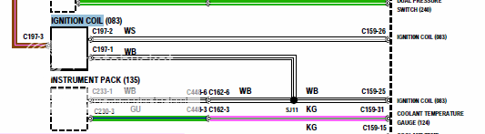
So what I am getting confused about is how I use the diode method if I only have a signal wire from one of the coils (Spark A). Do I tap into C197-2 WS wire? or could I make a circuit that takes the Spark A signal and simply doubles the pulse and outputs to Tach?
Thanks for everyone's help btw.
Luke.
Posted By: howie ll
Date Posted: October 23, 2014 at 6:32 AM
Again, tag an injector wire. How do you think we pick up tach on remote starts?
-------------
Amateurs assume, don't test and have problems; pros test first. I am not a free install service.
Read the installation manual, do a search here or online for your vehicle wiring before posting.
Posted By: lukeh
Date Posted: October 23, 2014 at 7:12 AM
howie ll wrote:
Again, tag an injector wire. How do you think we pick up tach on remote starts?
Sorry I missed your reply when posting my last one.
I have never thought about remote starts so I wouldn't have known the answer to your question. Surely I am still going to have the problem with the signal reading wrong. It's 2 injectors for 4 cylinders (siamese ports) so two pulses per engine revolution making the tach read double the speed.
Posted By: oldspark
Date Posted: October 23, 2014 at 7:18 AM
Assuming the IgCoils share a common +12V and hence are GND switched (from ignitors, ECU, points etc) then diodes with their lines towards each trigger (ignitor etc) with other ends joined to the tach input.
Add a pull up resistor (maybe 10k) to tacho +12V if the tacho isn't registering.
Add a series resistor (maybe 1k) if the tacho is erratic.
Posted By: oldspark
Date Posted: October 23, 2014 at 5:09 PM
Re your earlier reply which I missed (we seem to be out of sync... ha ha), it's the same with spark.
Injectors might fire as often as a spark, but some are sequential and some fire "wasted injection" or even every half rotation (ie, 4 cylinder). Some may change their squirts per cycle (eg, high RPM).
And as I said, at startup they may fire at fixed intervals - eg every 12.5mS equivalent to 160RPM or maybe other intervals.
Remote starts usually need a mere "is the engine running?" signal as opposed to accurately knowing the RPM as a tacho does.
Certainly some vehicles use injector signals for their tachos - especially diesels - but they be a constant pulse number per cycle (excluding perhaps when cranking).
I'd probably try a single coil source initially. To get the right pulse to RPM I'd first see if the tacho can be modified. It may be a simple as adjusting its calibration trimpot or changing a resistor (easy if you can switch select the number of cylinders or a capacitor.
As to pulse multiplication, division is usually easy. Multiplication is tricky (read: PITA & complex).
Posted By: howie ll
Date Posted: October 23, 2014 at 5:15 PM
Sorry Peter I was wrong and I take your point about tach sensing.
-------------
Amateurs assume, don't test and have problems; pros test first. I am not a free install service.
Read the installation manual, do a search here or online for your vehicle wiring before posting.
Posted By: oldspark
Date Posted: October 23, 2014 at 5:27 PM
Fine, but it is IMO a valid - and oft overlooked - solution.
(Especially when injectors are easily accessible... I know some IgCoils etc are a pain to get to!)
PS - I added the last line to my last reply after you posted your reply.
Posted By: lukeh
Date Posted: October 24, 2014 at 1:16 AM
Thanks for the suggestions. I have ordered a multimeter that will measure frequency so I can do some testing.
Some info i've read about the coil pack suggests it has one wire for each spark A&B from the ECU (pin 1 & pin2) and a ignition live (pin 3) so hopefully I can just tap pin 2 which will give me the signal for the second coil. Then using the diode method to tie the two together as tach input.
Posted By: oldspark
Date Posted: October 24, 2014 at 4:40 AM
For a 4 cyl tacho you'd want to diode both signals - eg, pin 1 & 2 or A &B (switched side).
It should be the same diode connection to ECU pins 1 & 2 since ECUs/CPUs are usually common collector output - ie, 0V/GND when on, and not connected to 0V/GND when off. For the ECU any 1N400x diodes will do, but I still suggest grabbing 1N4004 or 1N4007 as they can also be used for relay coil spike suppression.
Posted By: lukeh
Date Posted: October 30, 2014 at 5:48 AM
A quick update
I have purchased a Smiths tach on eBay that will suit the look of my car but it is for a 4 cylinder positive earth and obviously not suitable for my car but neither would a neg earth unit without modification.
I am going to be building the circuit found on this website LINK that will replace the circuit board in the tach allowing any configuration of input i.e. -ve from coil or ECU and it can be calibrated to suit my needs.
I could have purchased a ready made conversion board for about £43 but that would be the easy route and I wanted to learn as much as solve the problem. I know that I haven't designed my own circuit but building one based on someone else's design will still be satisfying for me (if it works!)
I will report back with how I get on in case anyone finds this post and wants to know for their own project.
Thanks for all the help everyone.
Luke.
Posted By: oldspark
Date Posted: October 30, 2014 at 6:57 AM
Have a look at the LM2907/LM2917 Frequency to Voltage Converter instead.
But have you confirmed it does need a pulse-ratio modification? If not, it should be simple enough to invert the signal (maybe just a cap, else a transistor).
But as before, changing ratio is probably just a cap or resistor change.
Of course old tachos often have failed diodes and (electrolytic) caps.
Posted By: lukeh
Date Posted: October 31, 2014 at 5:04 AM
oldspark wrote:
Have a look at the LM2907/LM2917 Frequency to Voltage Converter instead.
But have you confirmed it does need a pulse-ratio modification? If not, it should be simple enough to invert the signal (maybe just a cap, else a transistor).
But as before, changing ratio is probably just a cap or resistor change.
Of course old tachos often have failed diodes and (electrolytic) caps.
I will be testing the signal hopefully at the weekend to confirm whether it needs modification. The main reason I have decided to go with a new circuit board is that the tach I picked up is RVI and will need converting anyway, so the circuit I linked will give me the flexibility to calibrate how I want.
Thanks, I will take a look at the LM2907/LM2917 circuits before committing.
Luke.
Posted By: oldspark
Date Posted: October 31, 2014 at 6:28 AM
Bluddy RVIs! (I had to look up wth that meant, but then "ah - them!". Primitive things - good at the time - but my mid-1960s Jap cars had non-transformer types and so too my bikes - even my 1972 Ducati!)
See dummett's electronic tacho driver using LM2917N.
Ultimately only the moving coil (meter & needle) is of interest, all the rest can be ditched.
I liked the LM2907 or more 'universal' LM2917 as they should have been adaptable for any situation (ie, universal), and (from memory) damping can be set independently of the actual meter used.
Tho I designed the odd LM29x7 circuit, I never built one because I ended up using other tachos (staring with an $8 K-Mart tacho the replaced my temp etc combined "meter", to later 1980-1990 OEM tachos).
|