sequential turn signals
Printed From: the12volt.com
Forum Name: Lights, Neon, LEDs, HIDs
Forum Discription: Under Car Lighting, Strobe Lights, Fog Lights, Headlights, HIDs, DRL, Tail Lights, Brake Lights, Dashboard Lights, WigWag, etc.
URL: https://www.the12volt.com/installbay/forum_posts.asp?tid=116595
Printed Date: May 15, 2024 at 2:25 PM
Topic: sequential turn signals
Posted By: mikerupp
Subject: sequential turn signals
Date Posted: September 28, 2009 at 7:06 PM
Hello Guys,
I have searched the forum and saw that there were a few other threads that did not pertain completely to what I am after.
Here is my problem. As it sits, I have the module to make the lights flash how I want it, but when I do use the indicator, the running lights (dim brake lights) and if pressed, the brake lights will stay lit while the indicators are activated.
What I need is for the brakes and the running lights to be completely disabled until the indicator has returned to its normal position. As in, I do not want to see the running lights in between the blinks.
I was told that I need to have the brake & the running lights on relays and then need to have a capacitor before them to make the circuit stay on while the indicator is active.
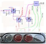
The tail lights have 4 circles. We are focusing on the last 3. The two in the middle are brakes and running lights. Both brakes are tied together for ease of wiring as well as the running lights are tied to each other. The brakes will be used as part of the sequential turn signals. So the lights will blink from inside to outside.
The indicator control module has is connected to all three and has a power input.
So if the lights were in front of you, you would see 4 different wires. Grounds, Brakes, Running and Indicator.
I really need help with the wiring diagram portion of how to I get these to blink like the older cars or the brand new Mustangs.
If I did not make this clear enough please ask me to clarify. I am just learning the electrical lingo.
Thank you in advance,
Replies:
Posted By: d_rock_81
Date Posted: September 28, 2009 at 11:08 PM
What kind of vehicle??
-------------
Dustin Rockney
Rockstar Autosports
Posted By: mikerupp
Date Posted: September 29, 2009 at 5:32 PM
94 Toyota Supra Turbo
Even though I dont think that matters.
Posted By: KPierson
Date Posted: September 29, 2009 at 8:45 PM
Not very elegent, but this should work: 
You can use the 12vdc output to energize more relays - one relay to cut each signal you need to cut. ------------- Kevin Pierson
Posted By: i am an idiot
Date Posted: September 29, 2009 at 8:52 PM
When you say the 2 middle ones are brake and tail light, one on each side of the vehicle? Or one for brake and one for tail on each side of the vehicle? This will be easy, I just need the above answers.
Posted By: mikerupp
Date Posted: September 30, 2009 at 4:10 PM
i am an idiot wrote:
When you say the 2 middle ones are brake and tail light, one on each side of the vehicle? Or one for brake and one for tail on each side of the vehicle? This will be easy, I just need the above answers.
Yes, I am referring to the two inside circles of each tail light. So I would want to cut out both of these on each side.


Posted By: i am an idiot
Date Posted: September 30, 2009 at 4:20 PM
And you want to have the brake and tail portion go out and remain out while the blinkers are on? But you want the brake and tail light elements to operate as two of the 3 bulbs in the sequence of the blinkers, is this correct?
Which of the elements do you want to work as the blinker? The parking lamp or the brake lamp? I think we can do this with 3 relays per side.
Posted By: mikerupp
Date Posted: September 30, 2009 at 6:19 PM
i am an idiot wrote:
And you want to have the brake and tail portion go out and remain out while the blinkers are on? But you want the brake and tail light elements to operate as two of the 3 bulbs in the sequence of the blinkers, is this correct?
Which of the elements do you want to work as the blinker? The parking lamp or the brake lamp? I think we can do this with 3 relays per side.
To use the pictures above as a reference I will explain what I am looking at doing on JUST THE PASSENGER LIGHT.
The left clear lens would be reverse ( FORGET ABOUT THIS ), the next two are used for running lights(dimmer) as well as brakes (brighter and my main focus) and the outer clear lens is the normal turn signal.
I have a control module that has the lights blink from inside to outside. So they are all set for that. The lights are LED's now and I have it set up on the circuit boards so that the control module can send a signal to each board in the specific sequence.
Posted By: i am an idiot
Date Posted: October 03, 2009 at 7:15 PM
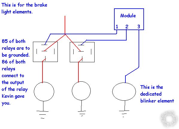
you will have to build the setup that Kevin posted earlier. That will give you a constant output to power the other relays. I did not realize that there were 2 for tail and the same 2 (different elements) for brakes. This will take 3 relays plus the one Kevin posted per side of the vehicle. Wire the third output from the module directly to the blinker lamp. You will have to wire a relay to kill the tail lights when the blinker is on. Wire it as follows. Cut the wire before the lamp, connect one end to terminal 30 of the relay. Connect the other end to terminal 87A. Connect the output of Kevin's diagram to terminal 86 of all 3 relays on that side. Ground terminal 85 of all 3 relays. You said earlier that there was one wire for the brake and one wire for the tail lights. You should connect both tail light elements to the one relay. You will need 2 relays for the brake elements. For the brake light elements, do just as you did for the tail lights except you need 2 relays, and this time it is crucial that the lamp is connected to terminal 30 and the wire that comes from the car goes to terminal 87A. Now on the relay on the inner brake light connect the first output of the module to terminal 87. On the relay connected to the middle brake lamp, (middle element of your blinker setup), connect the second output of your module to terminal 87.
Posted By: mikerupp
Date Posted: October 04, 2009 at 1:28 PM
i am an idiot wrote:
you will have to build the setup that Kevin posted earlier. That will give you a constant output to power the other relays. I did not realize that there were 2 for tail and the same 2 (different elements) for brakes. This will take 3 relays plus the one Kevin posted per side of the vehicle.
Wire the third output from the module directly to the blinker lamp. You will have to wire a relay to kill the tail lights when the blinker is on. Wire it as follows. Cut the wire before the lamp, connect one end to terminal 30 of the relay. Connect the other end to terminal 87A. Connect the output of Kevin's diagram to terminal 86 of all 3 relays on that side. Ground terminal 85 of all 3 relays. You said earlier that there was one wire for the brake and one wire for the tail lights. You should connect both tail light elements to the one relay. You will need 2 relays for the brake elements.
For the brake light elements, do just as you did for the tail lights except you need 2 relays, and this time it is crucial that the lamp is connected to terminal 30 and the wire that comes from the car goes to terminal 87A. Now on the relay on the inner brake light connect the first output of the module to terminal 87. On the relay connected to the middle brake lamp, (middle element of your blinker setup), connect the second output of your module to terminal 87.
Thanks!!!
Cant believe I am going to take advice from an idiot!! 
Appreciate the help.
Posted By: i am an idiot
Date Posted: October 04, 2009 at 3:39 PM
Let us know how it works out.
Posted By: mikerupp
Date Posted: October 04, 2009 at 5:23 PM
I wanted to make a visual diagram before I jump into it. Can you tell me if this looks accurate?

Posted By: i am an idiot
Date Posted: October 04, 2009 at 5:32 PM
I thought you were using the brake light elements as the blinkers. Is this correct? According to what you drew, you have the module connected to the lights. In my instructions the module is to be connected to the relays. When the blinkers are turned on, the relays are energized, which breaks the connection to the tail and brake light feeds. The relays then connect 87 to the lights. When the module sends a signal to 87, that will light that blinker.
Posted By: i am an idiot
Date Posted: October 04, 2009 at 5:38 PM
I will draw you a picture tonight. Are you planning to use the brake light elements as the blinkers? Or are you just wanting to turn the brake lights off during the blinker cycles?
Just to avoid confusion on the diagrams, I am going to draw one for the taillights and a separate for the brake light elements.
Posted By: mikerupp
Date Posted: October 04, 2009 at 5:46 PM
Yes the module will control each individual light to blink in the proposed fashion.
The brakes will be wired together to have one wire.
The running lights will be wired together to have one wire.
When I hit the turn signal to ON I want both of the brakes and/or running lights to turn off immediately, not one by one, until the turn signal is off.
Let me take a whack at this diagram again.
Posted By: mikerupp
Date Posted: October 04, 2009 at 5:47 PM
let me see if I can photoshop something up to show exactly what I am after.
Posted By: i am an idiot
Date Posted: October 04, 2009 at 6:03 PM
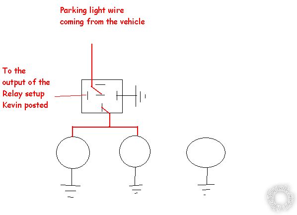
I need to know if you are planning on using the brake light elements as your blinkers? Or is there a dedicated blinker element and you just need to kill the brake and tail lights? The following diagram is assuming that you are using the brighter brake light elements as your blinkers. You have to wire them up independent of the other one because you are using them as 2 different elements of the blinkers. The red wire coming from the top of the picture is the brake light wire coming from the car.
Posted By: i am an idiot
Date Posted: October 04, 2009 at 6:14 PM
Thanks fot the 200K upload size.
Posted By: mikerupp
Date Posted: October 04, 2009 at 6:20 PM
I will not be using the wires for the brakes or the running lights. As I added my own to the custom circuit boards using LED's. So, yes I will be using a dedicated blinker wire for each light. I just need to kill the brakes and the running lights, correct.
A close look at just one of the brake light circuit boards and you will see a single wire for running lights, a single wire for brake lights, a single wire for the turn signal input, and a ground.
You will have that same thing again on the other brake light circuit board.
So, when I would turn the indicators on I would want the brakes to shut off completely and take the signal ONLY from the control module.
Posted By: i am an idiot
Date Posted: October 04, 2009 at 6:36 PM
Use my last drawing twice. One for the brake light wire and once for the tail light wire.
Posted By: mikerupp
Date Posted: October 04, 2009 at 6:37 PM
How about this? And if this is close, would the modules tail light input be connected to Kevins 87A? Connected before the diode? Connected where I have it?

Posted By: i am an idiot
Date Posted: October 04, 2009 at 6:38 PM
i am an idiot wrote:
And you want to have the brake and tail portion go out and remain out while the blinkers are on? But you want the brake and tail light elements to operate as two of the 3 bulbs in the sequence of the blinkers, is this correct?
Which of the elements do you want to work as the blinker? The parking lamp or the brake lamp? I think we can do this with 3 relays per side.
Posted By: i am an idiot
Date Posted: October 04, 2009 at 6:42 PM
The module needs to be connected to the output of Kevin's drawing. If you connect it where you have it, it would only come on when the blinker wire was getting power. Blink off blink off. Connect it to 87, not 87A
Posted By: mikerupp
Date Posted: October 04, 2009 at 6:48 PM
Ok i think this should do.
Posted By: i am an idiot
Date Posted: October 04, 2009 at 6:52 PM
You are using 87 on both of the relays. You need to use 87A instead.
Posted By: mikerupp
Date Posted: October 04, 2009 at 6:58 PM
Copy that. Updated.
I will try it out and let you know.
Thanks for all the help.
Posted By: mikerupp
Date Posted: October 04, 2009 at 7:09 PM
i am an idiot wrote:
The module needs to be connected to the output of Kevin's drawing. If you connect it where you have it, it would only come on when the blinker wire was getting power. Blink off blink off. Connect it to 87, not 87A
I just want to make sure I am understanding this. Cause this threw me a curve ball. Kevins output is 30. So the modules input needs to be connected to 30 or 87 now?
i am an idiot wrote:
You are using 87 on both of the relays. You need to use 87A instead.
Ok so both relays are getting their respective signals (brake and running lights) through 87A now.
This is updated to what I believe you are saying:
Posted By: mikerupp
Date Posted: October 11, 2009 at 3:01 PM
What capacitors would work for this application? I am searching for a 10K uf capacitor like the one in the diagram and can not find anything of the sort. They are in volts and then have another rating for uf.
So what would work for what I am trying to accomplish?
Posted By: i am an idiot
Date Posted: October 11, 2009 at 3:05 PM
You can parallel (2) 4700 microfarad capacitors.
Posted By: mikerupp
Date Posted: October 11, 2009 at 3:34 PM
i am an idiot wrote:
You can parallel (2) 4700 microfarad capacitors.
Thanks for the prompt response. This should be it, correct? 4700 uf 16v capacitor
Posted By: i am an idiot
Date Posted: October 11, 2009 at 3:44 PM
I always try to use 25 volt capacitors. Running them that close to their rated voltage has been known to cause problems. Your car is probably running at or above 14 volts. If all you can find locally are 16 volt caps, that will have to do.
Posted By: mikerupp
Date Posted: October 11, 2009 at 4:04 PM
i am an idiot wrote:
I always try to use 25 volt capacitors. Running them that close to their rated voltage has been known to cause problems. Your car is probably running at or above 14 volts. If all you can find locally are 16 volt caps, that will have to do.
Copy that. Here is a new one I found
Is there any certain store that you shop at to get some good prices?
Posted By: mikerupp
Date Posted: October 11, 2009 at 4:14 PM
https://..ca/4700uF-25V-RADIAL-LEAD-CAPACITOR-X30_W0QQitemZ380153480622QQcmdZViewItem
Posted By: mikerupp
Date Posted: October 11, 2009 at 4:20 PM
Well I wish I could just edit my post, but since I am a rookie here that is unlikely.
I guess the links dont work. Sorry about that.
This is what goes before the ca/4700 part if that might help.
https://..
Posted By: mikerupp
Date Posted: October 15, 2009 at 7:14 PM
Would a 36V capacitor work? They have them locally for $5.47 each. I dont feel like waiting for the ones to come in from over sea's that I already purchased. I know, Im getting all antsy. And if they would how many would I need? Just two, one for each side?
Posted By: i am an idiot
Date Posted: October 15, 2009 at 9:07 PM
Yes any voltage 25 or greater will work fine.
Posted By: mikerupp
Date Posted: October 20, 2009 at 6:31 PM
i am an idiot wrote:
Yes any voltage 25 or greater will work fine.
Say I do not want to run any capacitors in parallel. What would be the minimal voltage on the capacitor that I could use to pull that off? 35V? 50V?
Posted By: i am an idiot
Date Posted: October 20, 2009 at 7:55 PM
Paralleling a capacitor with another will still have 14 volts across it. 25volts or greater is what you need. You can use the 16 volt caps, just if you start having trouble with the setup, look at those caps before you spend any time troubleshooting the device.
Posted By: mikerupp
Date Posted: October 23, 2009 at 7:35 PM
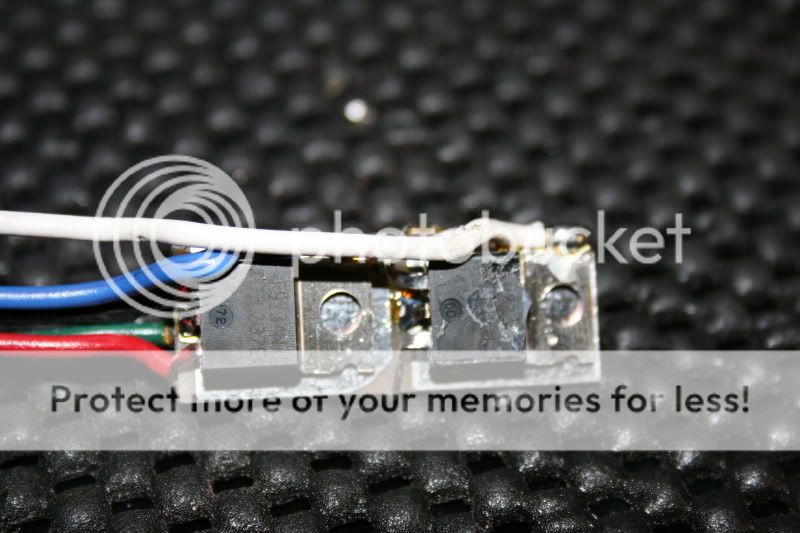
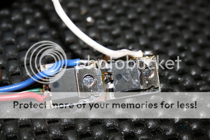
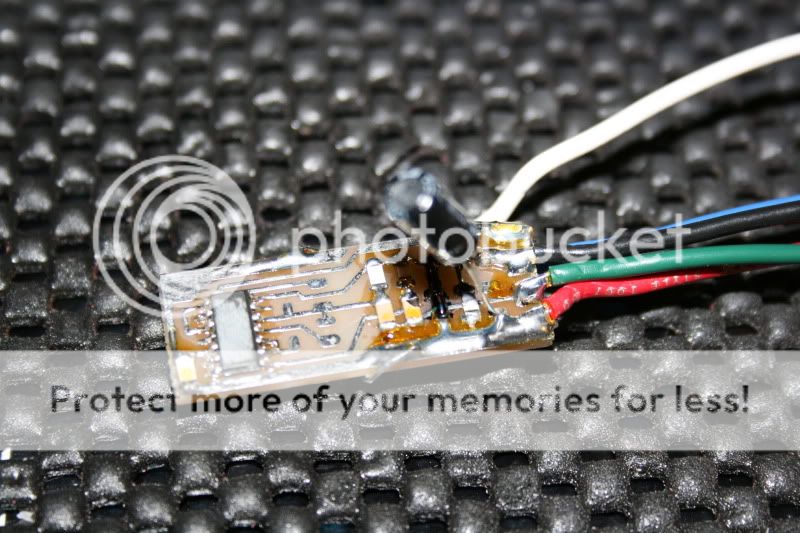
Could you help identify all these parts on this circuit board? Its two sided.
If you have the time to, can you use something like paint to write words over the parts? It would help a ton.
Thanks in advance.
Posted By: KPierson
Date Posted: October 23, 2009 at 8:36 PM
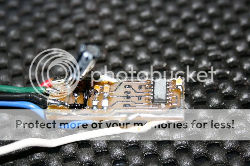
Based on the apparant lack of a power supply I assume it's a cheap device running at battery voltage (ie no central processor). The top pic shows two transistors, most likely mosfets. The bottom picture shows a chip (can you get a number off of it) a large cap (probably for timing), and a few surface mount parts (probably resistors). I would guess the chip is a counter or sequence of some sort. However, without the numbers off of it it is hard to tell. How much did you pay for that if you don't mind me asking? ------------- Kevin Pierson
Posted By: mikerupp
Date Posted: October 23, 2009 at 9:08 PM
The top pictures has this on both square things.
F9234N
I () R 237E
24 77
I can not make out what the bottom picture has labeled on it. But the unit is ran off of a tail light signal and it is for sequential tail lights.
Posted By: mikerupp
Date Posted: October 23, 2009 at 9:18 PM
The capacitor is 47uf 25V.
I can not tell what size the resistors are. They are all just a solid white color or a tan color.
The resistor looking things that are painted black are actually a glossy red color (anodized looking) when the black paint is scratched off. There is also a groove that completely wraps around the center of it. Cant tell if it is supposed to be black or is because it was painted.
Posted By: mikerupp
Date Posted: October 27, 2009 at 5:08 PM
Does anyone think they can replicate this design from what I provided? Or is there an existing design to control my brake lights in this fashion?
Posted By: mikerupp
Date Posted: November 20, 2009 at 11:26 AM
When wiring in these capacitors I see that one leg is longer than the other. Im assuming the longer is the positive and the shorter is negative? The short leg has a silver stripe with a minus sign in the center of it going from top to bottom of the capacitor. Would these be wired with the positive leg on the positive 12V tail light source and the other is to a ground? Or one is in and one is out on the same power source?
Posted By: mikerupp
Date Posted: November 20, 2009 at 11:39 AM
After looking at the diagram again, I realized that I need to put the capacitor with the negative leg to a ground source with a 10R next to it.
Still wish I could edit my posts.
|


