New guy, wiring an LED light bar.
Printed From: the12volt.com
Forum Name: Lights, Neon, LEDs, HIDs
Forum Discription: Under Car Lighting, Strobe Lights, Fog Lights, Headlights, HIDs, DRL, Tail Lights, Brake Lights, Dashboard Lights, WigWag, etc.
URL: https://www.the12volt.com/installbay/forum_posts.asp?tid=138623
Printed Date: April 28, 2024 at 7:41 AM
Topic: New guy, wiring an LED light bar.
Posted By: tackett
Subject: New guy, wiring an LED light bar.
Date Posted: March 08, 2015 at 10:08 PM
Hey there, I'm a new member and I joined this forum to maybe get some more info on car electronics. So here's my reason for posting.
I have a 2014 wrangler and I'm trying to wire up a 50" light bar. Now this is not my first time. I've wired up all kinds of crap in the past, but this one is really getting my goat.
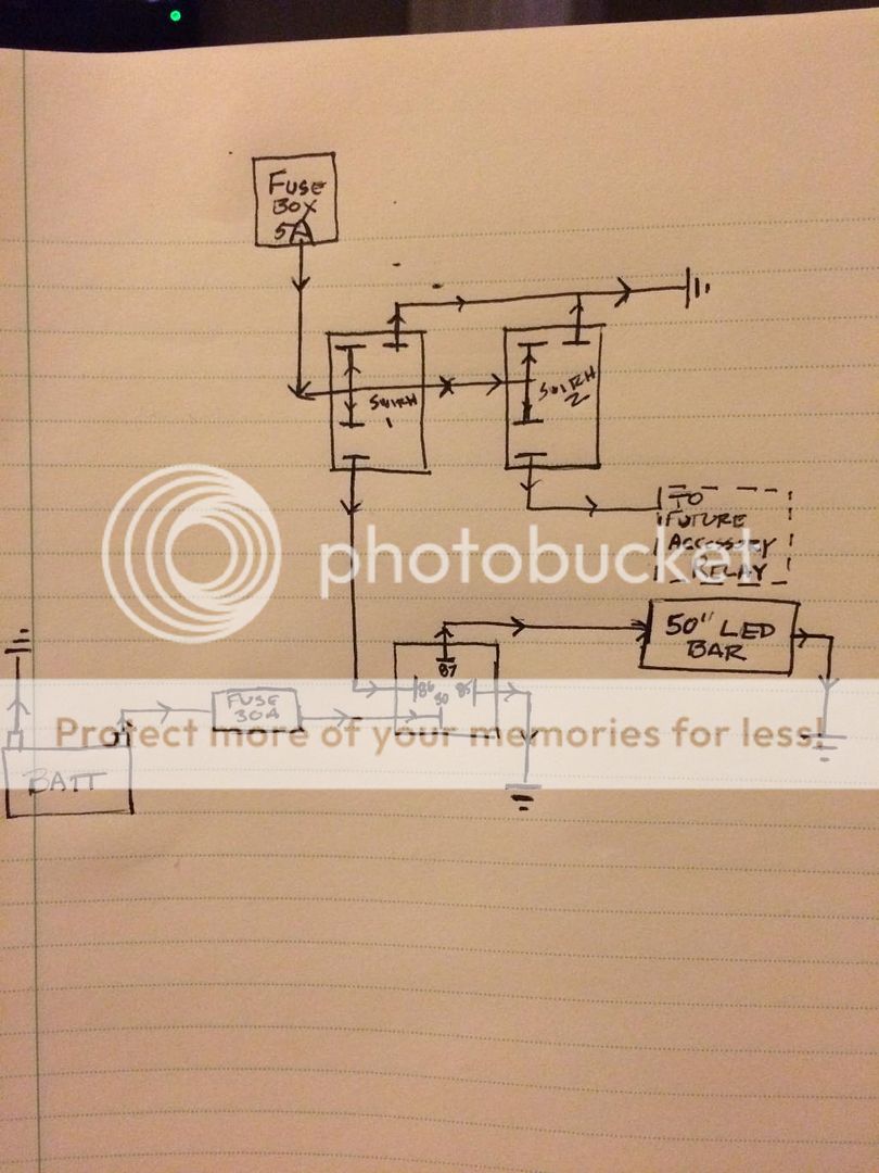
I wired it up with a simple relay. The wattage on the light is 300 watt and the operating voltage is 10-30 DC. I assume that means I can wire it up 12v just fine. 300/12=25amps. I used a 40a relay and a 30a fuse. I wired it up to a spst switch in the cab. Switch->relay, relay ground->chassis, battery->fuse->relay, light bar ground->chassis, relay->light bar positive.
I wired it that way and threw the switch. The light partially came on (one side did not light up.). While I was trying to figure out why the whole thing wasn't working, the positive side to the bar and the wire from the switch to the relay melted together (I had them ran in some loom together) and tripped the fuse.
So I have no idea why this happened. Any ideas?
Replies:
Posted By: oldspark
Date Posted: March 08, 2015 at 10:38 PM
Sounds like you have the switch in the power side and probably between +12V & GND. It should be between +12V & 86 else 85 & GND.
A faulty relay is possible but far less likely.
Posted By: tackett
Date Posted: March 08, 2015 at 10:43 PM
Maybe I jacked it up when I wired it.
Here's the schematic that I drew up to go off of:
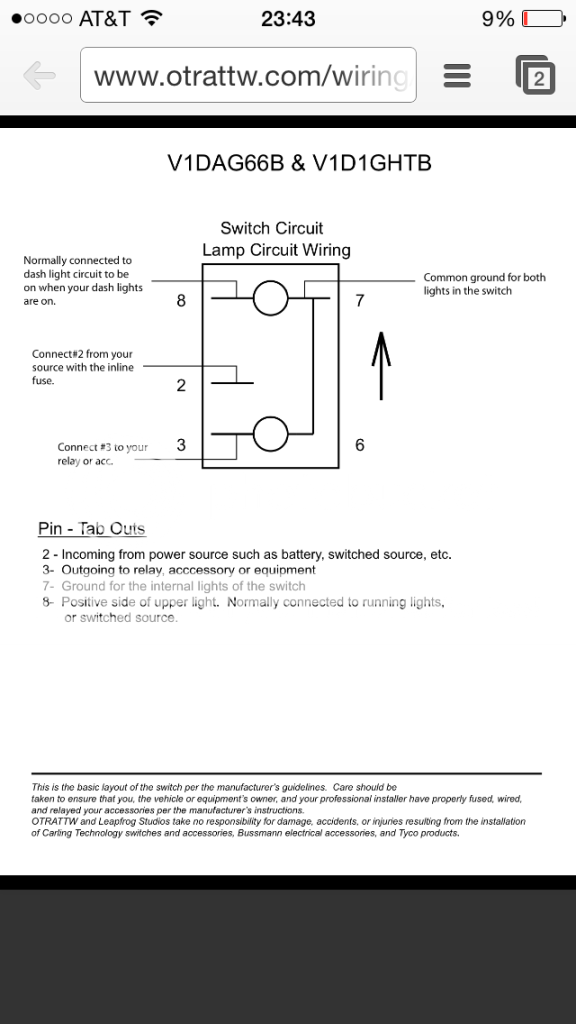
And here is the diagram for the switches:
https://www.otrattw.com/wiring/G66.pdf
When I get the time I'll tear it all back down and see just how much of the wiring melted out. Hopefully it didn't make it all the way up to the lamp.
Is the schematic I drew correct?
Posted By: tackett
Date Posted: March 08, 2015 at 10:47 PM
Here is a pic of the switch diagram so you don't have to open the link:
Posted By: oldspark
Date Posted: March 09, 2015 at 12:23 AM
That looks fine. Maybe try disconnecting +12V to terminal 8 in case the V1DA & V1D1 fig is not applicable - not that that explains any relay to bar burn.
And are you sure you are using power wire rated equal to or higher than the fuse rating?
Otherwise, re-reading your OP I regret skipping what I originally intended to say - try the bar direct to the battery (via a fuse unless wire melt is ok).
I assumed the fuse would blow in case of a bar fault ie an internal bar short. That however is unlikely since the bar tries to light thereby indicating some external fault, though it could still be internal and before its dc-dc converter or a faulty converter.
Cases like this require step by step testing. Test each part individually - eg, remove bar from chassis; try the bar direct to battery (both off and on chassis); the switch & relay without bar connected, etc.
Posted By: tackett
Date Posted: March 10, 2015 at 8:53 PM
Oh sorry I forgot I posted this.
Thanks so much for all the help. I just need to take another crack at it and see what happened. I'm hoping that the wire isn't jacked up all the way to the light itself and I can clip out the bad parts. I do have a couple more questions though.
1: if I want to buy a new seperate fusebox to run my accessories with, how can I get switched power to the box without tapping into a circuit with an existing load? Secondly how can I get some of these fuses to be switched and some of them to be constant? Like if I were to purchase this:Blue Sea Systems 5026 ST Blade Fuse Block with Cover https://www.amazon.com/dp/B001P6FTHC/ref=cm_sw_r_awd_r85.ub0CT3R06
How could I get some circuits to be switched and some to be constant?
2: does anyone sell a combination relay/fuse box so I don't have to have single relays hanging all over my engine bay? It would be SUPER nice to be able to have a box with relays and fuses, some switched, some constant that I simply have to plug in the output from the accessory switch.
3: I've heard that soldering connections is bad, it's always been the way I do it. Do I need to be crimping splices with waterproof butt connectors?
THANKS for all the help!
Posted By: tackett
Date Posted: March 10, 2015 at 8:54 PM
Oh sorry one more thing.
Does anyone know where I can buy waterproof relays with 10gauge pigtails?
Posted By: oldspark
Date Posted: March 11, 2015 at 9:22 PM
For switched & constant you'd need two 5026s since they appear to be a single supply box - ie, only one supply rail/bus.
Generally such installs use their own feeds from batt+.
Both have a main fuse as near batt+ as practicable that protects the feed - ie, rated no higher than the feed cable's and fusebox current capability.
The switched supply would use a relay to connect main power to the fusebox. The relay is energised from whatever switched source you want.
Posted By: txjeep
Date Posted: March 21, 2015 at 12:09 AM
Can you tell what gauge wire came with the light bar? The reason I ask is I have read about people buying cheap LED light bars off eBay that used wiring that was not sufficient to handle the draw, and they had to redo the wiring.
Posted By: oldspark
Date Posted: March 21, 2015 at 1:04 AM
If a wire gets warm then (IMO) it is too small. That is one of the tests for electrics - high resistance from bad contacts and undersized conductors results in heat (p = i*i*R).
In general for 12V LEDs the olde div-10 sizing rule should suffice - ie Wattage divided by 10 to give Amps - and then choose at least the next sized cable.
Otherwise use the LED's max current to determine cable size noting that that max may be at its highest or lowest operating voltage (see below).
FYI...
Cable ratings may be to prevent insulation breakdown in which case warmth & relatively high resistance (smaller diameter) may be acceptable.
Or cable ratings may be limit voltage drops (per length) within acceptable limits. IE - a thin cable may be fine temperature wise but result in too low a voltage being available at the load.
I suspect many cabling problems with high-power automotive LEDs result from cable sizing assuming 12V or 12.8V or 14.2V etc without realising they may be constant power loads whose cabling should be sized using the lowest voltage.
EG - a 27W LED that operates down to 9V will draw 3A @ 9V plus maybe a bit for inefficiency. [ie, does the LED itself use 27W or is that the entire LED module's rating? If the LED itself is 27W then its total input is closer to say 30W assuming 90% converter/ballast efficiency.]
Assuming 27W total load, that means 3A @ 9V compared to 2.1A @ 12.8V or 1.9A @ 14.2V.
{Note that high power/current LEDs usually have electronic drivers aka ballasts or converters; they rarely rely on mere resistors as do low power 20mA & 50mA etc LEDs. Tho such drivers were typically step-down aka buck converters with constant current (else voltage) outputs, these days buck/boost converters are often used since that's cheaper than using lower output voltages. EG, a 12V LED may be a 24V LED string since one converter with one 24V string is cheaper than 2 converters with two 12V strings. As a bonus, that "LED" can be used for 12V & 24V systems.}
I suspect too that because high-power LED output does not depend on input voltage - ie, wiring voltage drops are not as critical as they were for halogens - manufacturers have gone for thinner cables but have overlooked the thermal issues.
|