kicker kx 650.4
Printed From: the12volt.com
Forum Name: Car Audio
Forum Discription: Car Stereos, Amplifiers, Crossovers, Processors, Speakers, Subwoofers, etc.
URL: https://www.the12volt.com/installbay/forum_posts.asp?tid=113834
Printed Date: May 03, 2026 at 9:00 AM
Topic: kicker kx 650.4
Posted By: terry osborn
Subject: kicker kx 650.4
Date Posted: May 16, 2009 at 12:03 PM
I have a KX 650.4 that appears to be electrically dead. The amp has seen limited use and has never been abused. It worked one day,and the next day it didn't. I've checked the two 40 amp fuses in the amp and neither was blown. No led's are lit up. I pulled the amp to bench test it,as best that i was capable of. I did a close inspection of the circuit boards and didn't see any obvious signs of burns,scorching,etc. I didn't see any obvious broken solder joints on the board,but i didn't remove the board from the heat sinks for a closer look either. I powered up the amp and made sure that there was 12 volts thru the fuses and on the remote lug and figured this was my stopping point. I have an extensive background in electrical process controls,but a somewhat limited knowledge of intergrated circuitry,the components,their electrical values,properties and basic function. If someone has a better understanding and can point me to the next step in diagnosing the failed part it would be greatly appreciated. Or possibly recommend a reputable repair facility in the Dallas,Tx area. Thanks.Terry ------------- I've noticed one thing about "Experts". When one shows up,someone gets hurt!
Replies:
Posted By: i am an idiot
Date Posted: May 16, 2009 at 3:36 PM
Do not take the amp apart yet. In the following picture the 2 clamps to the left of the picture do need to be removed. Top left and bottom left clamp. With the amp disconnected, meter set to the diode test function. Below is a picture of the symbol that should be on your meter somewhere. 

Touch and hold one lead to the positive terminal of the amp, now touch the metal tab of one of the transistors that were uncovered by removing the clamps. Do one transistor on top of pic and one on the bottom of the pic. It should beep at you and read very near 0.000. Now touch and hold one lead to the negative terminal of the amp, other lead to the rightmost leg of the same transistors you checked the tab of earlier. Looking at the transistors when you can read the letters and numbers on the part is how you determine the rightmost leg. Let me know what you find out. You did use a volt meter to verify that you had power on both the remote and power terminals. When testing these voltages, hold the black meter lead to the negative terminal of the amp.
Posted By: terry osborn
Date Posted: May 23, 2009 at 2:34 PM
First i'll send an apology for not getting back sooner,workin that a... off. I did as you said and the meter went to zero when checking between the positive terminal and the metal tabs. The meter also went to zero when checking between the negative terminal and the right most legs of the transistors. I'll wait for your response to see where to go next. Have a great holiday and thanks for the help. ------------- I've noticed one thing about "Experts". When one shows up,someone gets hurt!
Posted By: i am an idiot
Date Posted: May 23, 2009 at 4:40 PM
There is a chip in the middle of the board, near the transformer, what is the number on that chip? TL494, TL594, SG3525, SG3524? I need to know the DC voltage on each pin of the chip. Be very careful to not touch 2 pins at once, especially 7 and 8, and 10 and 11. With the chip sitting so you can read the numbers, pin 1 is bottom left, pin 8 is bottom right. 9 is top right, 16 is top left. If it is a 494 or 594, Pin 8, 11, and 12 should have 12 volts. You will have to connected to remote, power, and ground to perform the above. Black meter lead to the ground terminal of the amp. Red lead to each pin.
Posted By: terry osborn
Date Posted: May 24, 2009 at 12:13 AM
Ok, The chip is a TL494CN and the voltage measurements are 1=.3, 2=.9, 3=.0, 4=.0, 5=.0, 6=.0, 7=.0, 8=1.1, 9=.5, 10=.5, 11=1.1, 12=2.2, 13=1.4, 14=1.4, 15=1.4, 16=4.5. ------------- I've noticed one thing about "Experts". When one shows up,someone gets hurt!
Posted By: i am an idiot
Date Posted: May 24, 2009 at 7:33 AM
Remove all the fuses from the amp and insert a single 10 amp fuse in one of the slots. using your meter lead, short pin 12 to pin 11 briefly, this should make the amp come on. We need to figure out why pins 8 and 11 are not getting power. If this makes the amp turn on, we have verified that lack of power on 8 and 11 is your problem. Remove power from the amp. Very important. With your meter set to ohms, or 20 ohm scale if it is not an autoranging meter, how much resistance is there between pins 8 and 11? If there is near 0 ohms between them, look for a 100 ohm resistor very near one of the pins. Brown Black Brown will be the first few bands of the resistor. Check it to see if it is reading well over 100 ohms. Also look for a transistor very near labeled on the board as Q1. If the resistor is ok and you find the transistor, let me know, I will tell you how to check it. DO NOT remove any part from the board, and do not remove any more clamps from the heat sink yet. If you read the last post before I deleted it, I thought pins 9 and 10 were 5 volts. It was not till I read it this morning that I noticed the decimal point. 5V good (.)5V not so much. Also look for a diode very near those components. Place your meter on the diode test function again and place a lead on each end of the diode, notice the reading, now reverse the leads to the other end and notice the reading again.
Posted By: terry osborn
Date Posted: May 24, 2009 at 11:56 PM
With pins 11 and 12 shorted the amp does not power up, Pins 8 and 11 ohm at .21 or near zero and the resistor marked brown black brown at R-39 reads 99.7 ohms. There are 5 diodes all close and they read as follows, D-1 .8634 reversed .5638, D-2 .8819 reversed .5633, D-5 .3195 reversed .3180, D-6 0 reversed .5637, D-9 0 reversed .5653
-------------
I've noticed one thing about "Experts". When one shows up,someone gets hurt!
Posted By: i am an idiot
Date Posted: May 25, 2009 at 12:46 AM
Did we ever check the voltage across power and ground, at the amp's input terminals? IS there a transistor labeled Q1 near the 494?
I misread another of your numbers, I thought 12 was 12.2 volts. Jumping the 2.2 volts of 12 to the 1.1 volts of 11 did nothing. Look for Q1, I will post instructions for you to check it tomorrow.
Posted By: terry osborn
Date Posted: May 25, 2009 at 2:43 AM
Yes,voltage was verified at 14.2 volts from the positive lug to the ground lug of the amp.I did find the transistor marked Q1 thats to the right of the 494.
-------------
I've noticed one thing about "Experts". When one shows up,someone gets hurt!
Posted By: i am an idiot
Date Posted: May 25, 2009 at 8:33 AM
Did you check the voltage of the remote wire? Try briefly touching the remote wire to 11 and 12 of the 494.
Posted By: terry osborn
Date Posted: May 25, 2009 at 10:25 AM
I have voltage on the remote lug and the amp powers up when jumper is placed between the remote and 11-12 of the 494. ------------- I've noticed one thing about "Experts". When one shows up,someone gets hurt!
Posted By: i am an idiot
Date Posted: May 25, 2009 at 5:56 PM
You need to check Q1 using the following page. https://www.bcae1.com/repairbasicsforbcae1/images/transistortestpage01.html If Q1 is ok, we need to follow the trace on the remote terminal and see where it goes. It should go to a diode and from there maybe several other components. I really don't think we need to remove the amp from the heat sink. Is it possible to take and post a picture of the area around the 494 and the remote terminal?
Posted By: terry osborn
Date Posted: May 25, 2009 at 6:01 PM
Camera is on it way. I'll have the picture and get it posted 10 minutes or so. ------------- I've noticed one thing about "Experts". When one shows up,someone gets hurt!
Posted By: terry osborn
Date Posted: May 25, 2009 at 9:25 PM
Pictures have been sent,let me know if they will work for you. I ran the test on the transistor at Q1,these are the results. 1=.0, 2=.9, 3=.0, 4=.9, 5=.7, 6=.8. I'm curious as to what values i should be seeing and why?
-------------
I've noticed one thing about "Experts". When one shows up,someone gets hurt!
Posted By: i am an idiot
Date Posted: May 25, 2009 at 10:22 PM
Pictures are fine, but I still need one of the remote terminal and the area right behind it. What is the number on the transistor? What does your meter read when on diode test and the leads are not touching anything or each other?
Posted By: terry osborn
Date Posted: May 25, 2009 at 11:29 PM
Sent the pics of the remote lug and ajacent area. The numbers on the transistor UTC, B649A,CREOA. My meter shows O.L on diode test with open leads. Using a Fluke 867B Graphical multimeter. ------------- I've noticed one thing about "Experts". When one shows up,someone gets hurt!
Posted By: i am an idiot
Date Posted: May 26, 2009 at 7:07 AM
You can see the trace coming from the remote terminal, it goes to the resistor which goes to ground, and it also goes north under the blue capacitor. Then it connects to the jumper that is partially covered by the glue of the yellow capacitor, that jumper is positioned east to west. Can you remove the glue and see where the trace goes from there? With the numbers of the transistor facing you, one meter lead on the right leg, the other lead on the left leg, notice the reading. Now move the left lead to the middle leg, notice the reading. Now reverse the leads and duplicate. The trace may go under the board from that point. We may have to take the amp out of the heatsink. There are a couple of thengs to watch out for when removing the board. I will give instructions if we need to take it out.
Posted By: terry osborn
Date Posted: May 26, 2009 at 11:49 AM
The trace runs north at the end of jumper 153 (east\west) and parallels jumper 39 then appears to run under the L2 power supply and back to the F1 fuse. The test on the transistor as follows: Blk lead Lft,Rd lead Rt =.9, Blk Lead center,Rd lead Rt =.7 Reversed Rd lead left,Blk lead Rt =.8 Rd lead, Rd lead center,Blk lead Rt =.6.
-------------
I've noticed one thing about "Experts". When one shows up,someone gets hurt!
Posted By: i am an idiot
Date Posted: May 26, 2009 at 2:02 PM
I have never noticed a fuse on that end of one of their amps, check it with your meter. When checking the transistor, you do have the meter on the diode test function? The numbers you are giving are not like any of the Fluke meters I own.
Posted By: terry osborn
Date Posted: May 27, 2009 at 9:52 AM
The reason the readings on the transistor appear foreign to you is because of operator error on my end. I seldom use this graph meter and noticed that diode test and cap test are on the same setting and one must toggle between the two.Sorry,my bad?
Maybe these will more resemble the correct values.
Lft Blk,Rt Rd =2.829
Center Blk,Rt Rd =2.763 begin 3.063 ending.
Lft Rd,Rt Blk=.630
Center Rd,Rt Blk= .03 begin 1.355 ending.
I sent a few more pictures to your e-mail, Close ups of the trace and the fuse configuration on the power end of the amp.
-------------
I've noticed one thing about "Experts". When one shows up,someone gets hurt!
Posted By: i am an idiot
Date Posted: May 30, 2009 at 4:42 PM
Recheck the transistor with the black lead on the right leg. It should read around (.)600 when you put the red lead on either of the legs. What is the number on the transistor? I know I got the number from you earlier, but it must have been in a PM and I can not find it.
Posted By: terry osborn
Date Posted: May 30, 2009 at 5:55 PM
With common or blk lead to the right leg of transistor and red lead to the left leg it reads .624. when red lead is moved to the center leg it reads 1.320 and climbs to 1.350.It takes about 3 seconds to get a stable reading. The numbers on the transistor are UTC B649A-CREOA.
-------------
I've noticed one thing about "Experts". When one shows up,someone gets hurt!
Posted By: i am an idiot
Date Posted: May 30, 2009 at 6:04 PM
Try again with the red lead on right leg. Black lead on each of the remaining legs. If this does not yield a (.)600 or so on both, that transistor is bad.
Posted By: terry osborn
Date Posted: May 30, 2009 at 6:56 PM
I didn't get a .600,it was more like a 2.345 on both legs.I'll wait for the next instructions.By the way,you may be able to help with this one too,looking for the end caps for a 75.2 Fosgate B&G. Works great and looks brand new,just missing the caps.
-------------
I've noticed one thing about "Experts". When one shows up,someone gets hurt!
Posted By: i am an idiot
Date Posted: May 30, 2009 at 7:32 PM
I doubt I have any endcaps, I do not take them in when I take an amp in for repair. It appears that the transistor is bad. Is there an electronics parts store in your area that may sell NTE replacement parts? If so an NTE 374 is the replacement for that part. You may be able to change it without removing the amp from the heat sink. If you decide to take the amp out of the sink let me know. You are looking at the side of the transistor with the writing on it when determining left and right?
Posted By: terry osborn
Date Posted: May 30, 2009 at 11:23 PM
Yes Sir, Always looking at the side with the transistor part number when establishing left \ right for test. There probably is a local source for parts,but i buy alot of stuff from Allied Electronics and they are a full line Distributor for NTE so it should be easy access. If you have a way to change the transistor without removing the amp from the heatsink,by all means do share. Looks as though solder is plentyful on the backside.
I should have the new part by mid next week. Again, thanks for your time helping with this.I hope to return it one day.
-------------
I've noticed one thing about "Experts". When one shows up,someone gets hurt!
Posted By: i am an idiot
Date Posted: May 31, 2009 at 3:57 AM
Heat the joints up and add just a little extra solder to each joint. Tilt the transistor front or back, whichever way will allow better access to the joints. Using a pair of small pliers, only to isolate your fingers from the heat. Lay your iron across all 3 legs of the transistor, moving your iron across them to get all 3 hot, gently lift up on the transistor. Do not pull hard, when the solder melts enough, it will just slide out of the holes. Now using either some desoldering braid or an Edsyn Soldapult (or any other brand of solder sucker) but if you have to buy one, get the Edsyn. Remove the solder from the holes and insert the new transistor.
Posted By: terry osborn
Date Posted: June 01, 2009 at 12:07 AM
When i solder in the new transistor,how much concern is there for over-heating the part? I'm not a novice in this dept and can make the connections rather quick,but had questions about how heat sensitive it might be. If it would be worthwhile to have some freeze spray or equivilent on hand. I don't have a de-solder pump,but i'll get one.How well does the solder braid work at wicking it away? I see the stuff everywhere,but never seen it in use. ------------- I've noticed one thing about "Experts". When one shows up,someone gets hurt!
Posted By: i am an idiot
Date Posted: June 01, 2009 at 5:49 AM
The braid works OK, you can get a small solder sucker for less than 20 bucks. Heat on the new transistor is not going to be an issue. If you do have to remove the board from the sink, you will have to remove both the front and rear covers, then the 3 screws from the pre-amp daughter board. Notice the 2 transistor clamps under that board are different from the rest of the clamps. They need to go back in the same position. All of the transistors are stuck to the pink tape that insulates them from the heat sink. You will have to use a pair of pliers on the side of the transistors and rock the parts off of the tape. You may want to grind any sharp edges off of the pliers. Try not to penetrate or scratch the tape. There are several screws that mount the board to the heat sink. The RCA and speaker terminal screws are not the same screws. Keep them separated so they go back in the same places they came from.
Posted By: terry osborn
Date Posted: June 02, 2009 at 9:33 PM
The transistor was simple enough to change out,didn't have to remove the board from the heatsink.I checked it afterwards and got the (.)600 you were seeking,and with leads reversed (.)600 again. With 12 v applied it powered up as expected. Is there anything else that should be tested or checked on the bench? ------------- I've noticed one thing about "Experts". When one shows up,someone gets hurt!
Posted By: i am an idiot
Date Posted: June 02, 2009 at 11:04 PM
That should be the only failed part. Connect a speaker to it and see if it plays. Wherever that is easier to do, on the bench or in the car.
Posted By: terry osborn
Date Posted: June 04, 2009 at 12:30 AM
Looks like you've pulled off another long distance repair my friend.All 4 channels of the amp are functioning as designed. I really appreciate your proffesionalism and the time you spent with this. If you'll give me a name and physical address i'd like to at least send you a certificate for a nice dinner,or if you prefer a contribution to this website or possibly a favorite charity,your choice. This site is absolutely the best i've seen for all things 12 volt. Take care. ------------- I've noticed one thing about "Experts". When one shows up,someone gets hurt!
Posted By: i am an idiot
Date Posted: June 04, 2009 at 1:10 AM
Hey, it was a pleasure to help you. If I asked 4 questions, I got 4 answers. It was really a pleasure. A contribution to this site will be great.
Posted By: terry osborn
Date Posted: June 04, 2009 at 11:01 PM
As you requested,and being one that honors his word,a contribution has been made to this website.I look forward to working with you again. Many thanks. ------------- I've noticed one thing about "Experts". When one shows up,someone gets hurt!
Posted By: i am an idiot
Date Posted: June 05, 2009 at 9:52 PM
Most people don't look forward to needing my help again. You should hope that all of your equipment remains in working order. However, i will be here if you do need help again. You left out the word "rather" in your signature line.
Posted By: terry osborn
Date Posted: June 06, 2009 at 1:07 AM
Yeah,your right.Most people wouldn't look forward to an equipment crash,but i'm alway's hunting for the next learning experience.
I left that word out of my signature line on purpose. You did so well with the electronics,thought i'd see how you faired with quotes.That's two up,way to go!
I have a 45 amp 120v to 12v converter made by Todd engineering. Same story line,no burns,scorching,blown fuses etc...Interested?
-------------
I've noticed one thing about "Experts". When one shows up,someone gets hurt!
Posted By: i am an idiot
Date Posted: June 06, 2009 at 2:06 AM
I am scared of 110 volts. But as long as you are the one probing the HOT wires, let's go for it. I am not familiar with that brand of supply. Is there a bank of TO-3 cased transistors? Is there a chip that looks very similar to the 494 of the amp? Number should be XX723 or XX729?.
Posted By: terry osborn
Date Posted: June 06, 2009 at 8:41 AM
I'll take a closer look at it,and i'll take a few pictures and e-mail them to you.Let you know when i've done so. 120v isn't a concern,i work with 4160vac and 600vdc daily.
-------------
I've noticed one thing about "Experts". When one shows up,someone gets hurt!
Posted By: terry osborn
Date Posted: June 06, 2009 at 11:59 AM
E-mailed pictures,should be in your box.There is 2 banks of transistors,4 in each.1st group on left at the 120v end.labeled Q1 thru Q4 are marked (IRF740\IR820F). 2nd group on right at 12v end labeled D1 thru D5,4 is ommited,marked (30CT0045\IR82F).These all attach to heatsink. 2 chips on the motherboard both have 8 pins,1 marked M76BB\393M, other marked CS3845B\9729J. Also have 2 chips on a plug-in companion board,a six pin marked CNY173,and an 8 pin marked M79A2.
-------------
I've noticed one thing about "Experts". When one shows up,someone gets hurt!
Posted By: i am an idiot
Date Posted: June 06, 2009 at 2:52 PM
The 740s are Mosfet power supply transistors. The ones labaled D are the rectifier diodes. The chip I was asking about is in some older power supplies. What exactly is the supply doing or not doing? Have you checked the fuse with a meter?
Posted By: terry osborn
Date Posted: June 06, 2009 at 4:13 PM
Yes,i have checked the fuse and gone so far as to check for available 120v downstream to the transformer.Also checked for output on the secondary from the transformer.It seemed to be ok.
Story on this is: It has 2 voltage settings depending on the switch 13.2vdc and 14.4vdc.It was left in the 14.4 vdc to quick charge the battery and at some point the internal fan had come apart,and i would guestimate things got a bit hot.Considering that it was inside a closed cabinet,inside a closed up aluminum racecar trailer,in july,and in Texas.
-------------
I've noticed one thing about "Experts". When one shows up,someone gets hurt!
Posted By: i am an idiot
Date Posted: June 07, 2009 at 7:00 AM
What kind of AC voltage do you have on the secondary side of the transformer? Is the secondary of the transformer connected to the Diodes? The ones labeled D1 to D5.
Posted By: terry osborn
Date Posted: June 07, 2009 at 9:37 AM
I'm going to recheck the voltages on the transformer,primary and secondary I don't believe i got a positive reading on either in Vac.What seems odd is that i pick up Vdc downstream of the transformer,and the power on L.E.D is illuminated now.This was not the case before. The transformer appears to be a 16 pin multi-tap. What pins should i get readings on when checking the primary and secondary side. It's configured with 8 pins on primary and 8 on secondary,4 on left\4 on right.I work with large multitaps up to a million amps and jumper placements determine either buck or boost.However,i have a diagram for correct configuration and for this one i don't.
-------------
I've noticed one thing about "Experts". When one shows up,someone gets hurt!
Posted By: i am an idiot
Date Posted: June 07, 2009 at 9:58 AM
You will need to check from one leg to the other 7 and then check from leg 2 to the other 7. Check all possible combinations and just let me know the highest voltage you come up with. The unit may be equipped with a thermal shut off device. Was there anything mounted to the heat sink other than the FETs and the Diodes?
Posted By: terry osborn
Date Posted: June 08, 2009 at 12:30 AM
I rechecked the transformer and i'm not seeing any Vac on the primary or secondary.I traced the 120vac to find where it stops. It appears to end at a large 4 pin component which is clamped to the heatsink,on the opposite side of the mosfets.This component is the only thing that clamps to this side of the heatsink and it's close to the 120v supply plug.I'f you need a part# to identify it,i'll see what i can do.May have to remove it to get #.
-------------
I've noticed one thing about "Experts". When one shows up,someone gets hurt!
Posted By: i am an idiot
Date Posted: June 08, 2009 at 6:13 AM
Do not take it out, take a picture. Is it a rectangular device with 3 right angle corners and one corner is 45'd twice? If so, it is a full wave bridge rectifier. It converts AC to DC voltage. The 2 legs that do not go to the transformer should have DC voltage on them. Black lead on one leg red lead on the other.
Posted By: terry osborn
Date Posted: June 08, 2009 at 10:36 PM
Ok, let's see if can deliver correct answers to several pending questions.There is no Vac present on the primary or secondary of the transformer.Yes,the 4 diodes labeled D1 thru D5 are connected to the transformer.Your description of the component in question sounds exactly like what i see. I have 120vac present between 2 legs of the rectifier.The only DC voltage i see at the rectifier is millivolts.I'm sending pictures to your E-mail for review.
-------------
I've noticed one thing about "Experts". When one shows up,someone gets hurt!
Posted By: i am an idiot
Date Posted: June 08, 2009 at 10:43 PM
Unplug the unit and check the 4 legged device. It is basically 4 diodes in one case. Black lead on one of the legs that has the AC voltage, red lead to one of the others. Then the other. Reverse leads and check again. I have no pictures yet. gonna keep looking.
Posted By: haemphyst
Date Posted: June 09, 2009 at 7:39 AM
:::::THREAD HIJACK!!!::::: 
The bridge can't be connected to the primary side of the transformer. That is indeed the low voltage side of the circuit. Also, your description of millivolts on the DC legs of the bridge sounds to me like an open bridge. I think that's your defective component...
If there is no voltage present at the primary side of the transformer, (is that the case, or did I misread somewhere?) I expect there might be a thermal fuse gone off somewhere. They are commonly shaped like a small bullet, with a resin "nosecone" and a metal tube body, and the ends attached to relatively heavy gauge leads.
Picture one... (These are the most common, in household, low-current devices like your power supply.)
Picture two...
They are sometimes buried inside the transformer, and if you don't see one, this may be the case.
One additional test, if I may suggest: Unplug the power supply. Turn power switch to the "on" position. Test for continuity between the two prongs of the AC plug. Is it a three prong plug? If so, also check for continuity between the ground prong, and the other two (hot and neutral) prongs, in both on and off power switch positions. Post back here, and let me know what you find. If there is no continuity, then your failure is MOST likely on the primary side of this paticular power supply, and best bet is the thermal fuse, unless there was an over-current condition as well as the thermal condition...
As the input side has to have AC to work, the polarity of your meter jumpers won't matter, but only in this case.
Is there a part number or model number on the transformer itself? ------------- It all reminds me of something that Molière once said to Guy de Maupassant at a café in Vienna: "That's nice. You should write it down."
Posted By: i am an idiot
Date Posted: June 09, 2009 at 8:37 AM
Not that kind of supply. This appears to be some new fangled device that has no transformer like we both were thinking. It appears as though they rectify the 110 and built a DC to DC supply to step it down to 13.8. I too am suspecting a bad bridge. He is checking that for his next post. 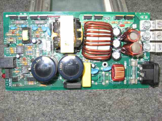
Posted By: haemphyst
Date Posted: June 09, 2009 at 2:48 PM
Yep... Switcher. I'm out! LOL Analog power supplies for me, baby! :)
PLEASE be careful! The output DC on the input side of that thing (on the left side of the yellow block) will be better than 170VDC. That's only going to be current limited by the input fuse. It'll bite, and HARD!
Looking at it again, you say there is no VAC at the bridge input side? Check for a cold solder on the filter choke, it's the smaller choke on the lower right of the presented picture. That choke is in series with the circuitry following, it's nothing more than an RF filter.
The input side also will have two little turquoise discs. Those are MOVs. Check for voltages on both sides of those, as well. Those will probably be connected from hot to neutral and from hot to ground. Not very likely they will be conneced in series.
-------------
It all reminds me of something that Molière once said to Guy de Maupassant at a café in Vienna: "That's nice. You should write it down."
Posted By: i am an idiot
Date Posted: June 09, 2009 at 3:09 PM
This is my first experience with such a device. Learning as we go. But I am here till the end.
Posted By: haemphyst
Date Posted: June 09, 2009 at 5:38 PM
i am an idiot wrote:
This is my first experience with such a device. Learning as we go. But I am here till the end.
And I'll help where I can... ;) ------------- It all reminds me of something that Molière once said to Guy de Maupassant at a café in Vienna: "That's nice. You should write it down."
Posted By: i am an idiot
Date Posted: June 09, 2009 at 8:42 PM
terry osborn wrote:
I'll take a closer look at it,and i'll take a few pictures and e-mail them to you.Let you know when i've done so. 120v isn't a concern,i work with 4160vac and 600vdc daily.
He's laughing at 170 volts.
Posted By: haemphyst
Date Posted: June 09, 2009 at 9:38 PM
DOH! :)
-------------
It all reminds me of something that Molière once said to Guy de Maupassant at a café in Vienna: "That's nice. You should write it down."
Posted By: terry osborn
Date Posted: June 11, 2009 at 12:01 AM
Alright,those pictures i promised should be in your mail box,along with a few questions.I am conviced that there is no vac or vdc present at the transformer.The small yellow block ahead of the rectifier is marked 474k\250vac,it has 120vac present.
I checked the choke or RF filter for continuity.it checks ok.
Provided that i understand what components are the mov's,i have 120vac present on 1 when checked to common or ground,the other has no voltage present.
Now,the rectifier has me wondering what the h...
When i check this thing,meter set to vac and i.d side facing me,post 1 and 2 reads 119 vac,post 2 and 3 read 0,post 2 and 4 read 119 vac,post 3 and 4 read 0,and post 1 and 4 read 0.
When checked with meter set to vdc,post 1 and 2 read 168vdc,post 2 and 3 read 0,post 3 and 4 read 172vdc,post 1 and 3 read 172vdc and post 1 and 4 read 341vdc.
Normal???
-------------
I've noticed one thing about "Experts". When one shows up,someone gets hurt!
Posted By: haemphyst
Date Posted: June 11, 2009 at 12:43 AM
1: The MOVs are probably connected from hot to ground (the 120V reading), and from neutral to ground (the 0V reading). I expect these are OK, and those are correct readings...
2: The yellow block is indeed a cap, (47 microF) and is very likely there as either RF filtering or power factor correction. Can you tell if it is before the rectifier in the circuit, or after? If before, it is functioning correctly, and those are proper readings.
3: Can you provide some numbers off the rectifier? I'm betting that those are NOT normal readings, but without knowing what the part number is to reference it, I can't say for sure. It does sound as though you have a bad bridge, with one shorted, and possibly one open diode. This is not good, as you could have fried downstream parts with AC running through DC designed parts. :}
While you are at it, can you let me know the values on the big caps after the bridge? The two big black ones... And maybe a pic of the underside of the board?
:::::EDIT:::::
Additional bad news... Todd Engineering is LONG since out of business... In searching many forums for the schematics, I have been able to set the OOB date as somewhere around 2002-2003. Seems they built garbage power supplies, and Fleetwood abandoned them as their power supply of choice MANY years ago. Noisy, both physically and electrically, there are many people searching for repair support for similar power supplies...
-------------
It all reminds me of something that Molière once said to Guy de Maupassant at a café in Vienna: "That's nice. You should write it down."
Posted By: i am an idiot
Date Posted: June 11, 2009 at 6:42 AM
Well with 341 volts we should be able to power anything a race car trailer can throw at it. Seems as though the Rectifier is working fine. The transformer is not connected to the AC voltage from the wall. The AC from the wall goes through the rectifier and is converted to the DC voltage. Then there is some chip like the 494 that pulses that outrageous DC voltage. That is why the transformer is so small. I will be back this evening and look at the pictures.
Posted By: haemphyst
Date Posted: June 11, 2009 at 9:27 AM
It'll be the same as an amplifier power supply - no, really... You know those! :) Only difference is the input side is rectified wall current - so it's higher voltage and lower current!
The 341V reading is odd, but reconsidering it, I suppose it COULD be that high. If he is reading the positive terminal of the bridge (which would be 170V to ground), to one of the AC terminals (which would ALSO be a pulsed 170Vpk), that'd read 340V or thereabouts, depending on the meter. I don't know how he could have gotten 0V on some of the other readings he got...
i am an idiot, have you seen any pictures of the underside of the board? The big filter caps - are they wired in series or parallel? Is this a two rail input to the switching section or a single rail? If the caps are wired in series, it's likely to be tapped, and a dual rail, with a cap on each rail. Not that it matters to ME, really... It might be helpful information for you, though.
I'm still leaning toward a fried bridge.
-------------
It all reminds me of something that Molière once said to Guy de Maupassant at a café in Vienna: "That's nice. You should write it down."
Posted By: terry osborn
Date Posted: June 11, 2009 at 11:28 AM
Hey, I appreciate the group effort,didn't realize this thing might be a fubar.LoL..! Already aware about Todd Engineering and the junk they turned out.This supply failed when it was less than 2 months old back in 1998.They replaced it with a larger supply which i've had no problem with,and said keep the failed unit,you'll need it! Confidence in their product and free part's. Woo Hoo!
I kept this thing anticipating that one day,3 men from different diciplines,separated by many miles would converge and restore life to something that was born dead to begin with.
I'll get you the #'s off of the caps and the #'s off of the rectifer and post here later today.
170VDC is no LAUGHING MATTER! It ruined a nice pair of needle nose pliers. Ah,the shame of ignorance is so hard to live with.
-------------
I've noticed one thing about "Experts". When one shows up,someone gets hurt!
Posted By: i am an idiot
Date Posted: June 11, 2009 at 6:53 PM
If you PM me your e-mail address or clear your PM box, I can send you the pictures that he sent me. I have not tried to PM you in a while, but it was always full. He did send me one pic of the bottom of the board. I will look. Terry, check the DC voltage on the metal tab of the IRF 740s First black lead on ground and red lead on the tab of each transistor. Then black lead on tab of transistor on end of row. Red lead on tab of transistor on the other end of the row. I need to look at the chips in the picture and see if I can figure out which one does the job of the 494 in your amp.
Posted By: terry osborn
Date Posted: June 12, 2009 at 12:22 AM
Information requested::
The rectifier is marked RFE or possibly RPE,KBU-1004 AC.
The 2 large capacitors are 1500uf\200v.
I'll check the voltage on the 740's and post tommorow?,today? You know what i mean!
-------------
I've noticed one thing about "Experts". When one shows up,someone gets hurt!
Posted By: haemphyst
Date Posted: June 12, 2009 at 12:53 AM
Thats a 400V/10A full wave bridge, with the AC input on pins 2/3. Here's the sheet... Only rated to 150°C, WITH a heatsink, it may still be the offender.
OK... 2-3 voltage should be 120VAC. 1-4 voltage should be about 170VDC. 1-2 voltage COULD be zero or up to 340VDC, depending on whether pin 2 is neutral/ground or the AC hot leg. Same parameters apply for 3-4.
The caps (and I am speculating based on their values) are likely wired in series with a center tap, so you have two rails. A 0V reference, (the tap leg between the caps) a -170VDC, and a +170VDC. This is where your 340VDC reading came from in your earlier post. These are the DC voltages that are chopped to feed the primary side of the transformer. I also noticed three lugs on the output side... Two positive, and one ground?
Re-reading your post with the measured voltages, there MAY be some sort of doubling going on in there... With the cap on the input side (the yellow one), it could happen. I'll want to see pics of the underside, but those numbers don't sound right. ------------- It all reminds me of something that Molière once said to Guy de Maupassant at a café in Vienna: "That's nice. You should write it down."
Posted By: haemphyst
Date Posted: June 12, 2009 at 8:00 PM
Got the pics you sent me. Seraching the web got me to this forum, where in the second page of that thread there is a large backside photo of the very PS we are examining.
I am one of the last people ever to say "It's a loss", (I generally love a challenge) but with all of the control circuitry, the high(er) frequency choppers, the lack of an o-scope... This one might be a loss.
My suspicions were correct, however. It's a dual rail ±170VDC power input to the low voltage side. The large transformer is the step-down from the switcher (chopper), the four transistors to the upper left on this thread's picture are the choppers, the four diodes to the upper right are the rectifiers for the 12V output.
This, sadly is about as far as I can go... i am, you're up!
There isn't much filtering happening there... Those are pretty small caps for ripple control, and the inductors, being iron core, won't be really effective until higher end currents are reached. If you get this fixed, what woould you want to use it for? It's gonna be really noisy... ------------- It all reminds me of something that Molière once said to Guy de Maupassant at a café in Vienna: "That's nice. You should write it down."
Posted By: terry osborn
Date Posted: June 13, 2009 at 7:27 PM
It will be used for 12vdc lighting and to charge the auxillary battery's,if repairable.If not,it will become a small boat anchor.If it's up to the task!!!
-------------
I've noticed one thing about "Experts". When one shows up,someone gets hurt!
Posted By: i am an idiot
Date Posted: June 13, 2009 at 8:09 PM
Hey I forgot to look and see if I can figure out which chip is used to pulse the DC voltage. Going to go check that now. The discoloration on the bottom of the board, what component is connected to the trace that got hot? When a manufacturer determines that there is a part that is failing more than they expected it to, they mount them in a socket. I noticed that all 3 of the integrated circuits are mounted in sockets. That is not going to help us narrow it down.
Posted By: terry osborn
Date Posted: June 14, 2009 at 12:24 PM
I went back thru the preceeding post and hopefully this will get us back on track.
The dc voltages on the 740's,
I checked these both ways: Blk lead to ground of incoming 120vac,and to the 12vdc ground.Red lead to the metal tabs of the 740's.Just making sure everything is as it should be.
#1 167vdc.
#2 167vdc.
#3 -1.9 to -2.1
#4 -1.8 to -2.3
Last test: Blk lead to tab of left 740,Rd lead to tab of right 740 on the end = +7.1 to +8.3 vdc unstable.Reversed leads and readings were the same,but negative.
Full wave rectifier...
Post 2 and 3=+120vac.
Post 1 and 4=+340vdc.
Post 1 and 2=+167vdc.
post 3 and 4=+167vdc.
2nd post is 120vac hot.
3rd post is 120vac neutral.
If i read previous post correctly:
Post 1 and 2 should have rendered 0volts or 340vdc.
Post 3 and 4 should have been 0volts.
Post 2 and 4 rendered 167vdc just in case it was needed.
The discoloration or heat marks on the back side trace: The component in question is a diode marked D-13.The discoloration is not as severe to the other side of this diode,but the trace goes to a socketed chip marked 393N.
-------------
I've noticed one thing about "Experts". When one shows up,someone gets hurt!
Posted By: i am an idiot
Date Posted: June 14, 2009 at 2:55 PM
I would try replacing the comparator it is an LM393 or an NTE 943M.
Posted By: terry osborn
Date Posted: June 14, 2009 at 8:11 PM
Looks like a simple changeout.But,looks can be decieving? Heat sensitive?How does the socket help with parts that overheat?
Any other parts that may have toasted downstream? I don't mind purchasing maybe's. The freight is generally more than the cost of parts.
Oh Yeah, Thanks again for your time and effort.I've enjoyed the experience!.....
-------------
I've noticed one thing about "Experts". When one shows up,someone gets hurt!
Posted By: i am an idiot
Date Posted: June 14, 2009 at 8:42 PM
The sockets have nothing to do with heat. When they notice that a part is failing more frequently than they expected it to, they mount it in a socket so they can pay some rookie minumum wage to change the part out. If that fixes the unit they ship it back out. If it does not, then they send it to the technicians for more troubleshooting. Search for the other chips using the numbers on them. Let me know if you can not find info on them.
Posted By: terry osborn
Date Posted: June 16, 2009 at 12:23 AM
I try my best to refrain from "Dumb Questions" but occasionally i'll let one out just to see if anyone is listening.
My good sense(I stay away from that common stuff) tells me that it shouldn't make any difference what position this board is in during testing.
However,with the back of board facing up or on it's side(as this was the case for all data that was collected)I get results very different than if i test with the back down and components facing up.
It's near impossible to get to all the components in this position,but my curious nature led me to the four "740's". The voltage's on the 1st pair=48vdc on pins 2&3.2nd pair=0vdc. Flip the thing and the same pins read -167vdc.
Could this be because the board is in contact with a bench rug when the back is down? Just wondered what your thoughts were.
-------------
I've noticed one thing about "Experts". When one shows up,someone gets hurt!
Posted By: i am an idiot
Date Posted: June 16, 2009 at 12:50 AM
With all of the problems that other people are having with the supplies, it is very likely that there are several bad connections on the circuit boards. You should not be getting different readings, that is definitely not being caused by the surface you have the board sitting on. You may want to check for broken legs on all heat sink mounted components. Easiest way is to heat the joint up on the bottom of the board. The broken legs will move, you will see what I mean if you have a broken one. Also any where there is a feed through (a trace that ends at a hole in the board. Then travels through the board and continues on the other side of the board) You may want to heat them up, remove the solder and solder a wire or leg of a resistor through the hole. I remember E mailing you a picture with what I thought was a bad solder joint, did you add some solder to it?
Posted By: terry osborn
Date Posted: June 17, 2009 at 1:03 AM
Good to know that i'm on the right path. I certainly couldn't see a (for the most part) non-conductive surface making any difference.However,i'm also aware of what can be lurking in unexpected places,such as anything that contains a sufficient amount of poly.I did solder the joint you had circled,and it was broken.It was one of the mov's.I don't know how you seen that in a picture,i looked that backside over with a 10x jeweler's lens several times and still missed it.
I'll check the joints of the 740's under heat and let you know whats up with that.
-------------
I've noticed one thing about "Experts". When one shows up,someone gets hurt!
Posted By: i am an idiot
Date Posted: June 17, 2009 at 5:43 AM
Look at the picture again, notice the ring around the leg of the component. Not the circle I drew, but the ring in the solder. When the joint breaks, it almost always makes a ring like that.
Posted By: terry osborn
Date Posted: June 17, 2009 at 7:49 AM
No need to look at the picture again,when it was identified(by the Master)the rookie took another look,and there it was.The break was so clean it appeared(to me)to be discoloration of the solder,not a defined break as one might invision.
Grasshopper learned valuable lesson from Sensei...: Question and scrutinize appearance.
-------------
I've noticed one thing about "Experts". When one shows up,someone gets hurt!
Posted By: i am an idiot
Date Posted: June 24, 2009 at 8:19 PM
I know you didn't tucker out on me. ------------- Let's Go Brandon Brown. Congratulations on your first Xfinity Series Win. LGBFJB
Posted By: terry osborn
Date Posted: June 25, 2009 at 3:46 PM
No way. I've been waiting on another failed supply to arrive(same brand and 10 amps larger)for parts.
-------------
I've noticed one thing about "Experts". When one shows up,someone gets hurt!
|