2 alternator house and chassis battery
Printed From: the12volt.comForum Name: Car Audio
Forum Discription: Car Stereos, Amplifiers, Crossovers, Processors, Speakers, Subwoofers, etc.
URL: https://www.the12volt.com/installbay/forum_posts.asp?tid=129298
Printed Date: May 21, 2026 at 7:42 PM
Topic: 2 alternator house and chassis battery
Posted By: alcapon1
Subject: 2 alternator house and chassis battery
Date Posted: November 20, 2011 at 3:02 AM
OH, PLEASE PLEASE PLEASE DO NOT NOT TELL ME THAT THE SAME THING CAN BE DONE WITH A HO ALTERNATOR. I want separate systems so thats the point. K

-------------
wire the world
Replies:
Posted By: oldspark
Date Posted: November 20, 2011 at 3:33 AM
But otherwise...
Firstly you have the power wire coming from the voltage regulator. What are you using - generators?!
Alternator power wires come from the alternator (B or B+) and have nothing to do with the Voltage Regulator (except the sensing for single-wire D+ type alternators).
Secondly, are you wiring 2 alternators in parallel?
Do that at your own peril of suitable advice - unless that Voltage Regulator is a "power" combiner (but it won't be (?)).
Thirdly, if 2 batteries, how are they interconnected? (Presumably a voltage regulator (charge light) controlled relay or one of those dumb "smart battery isolators" (not dumb if you have no charge light or other charge indication).)
If the battery/s is/are "electrically" remote from the alternator - ie, there is a reasonable resistance through their inter-GND & +12V connections - then you should have the 2- or 3-wire (etc) voltage regulators - ie, those with an S = Sense terminal that goes directly to each respective battery's +12V post.
If using alternators with external voltage regulators, I suggest getting internally regulated alternators, else mounting their voltage regluators on the alternator, else ENSURING real good engine (alternator) to battery- GND connections.
The latter is really the crux of the issue - if the alternator's regulator's GND drifts from the battery- (GND), the alternator will increase output voltage and may blow car electrics (except for single-wire D+ alternators).
Posted By: alcapon1
Date Posted: November 20, 2011 at 3:48 AM
My biggest question revolves around the regulator, I have been reading about internal regulators but I just want to regulate the second alternator the same way that the jeep does if possible. I was thinking about running a internal regulator but I am not really sure if it is needed. I want to use the stock alternator on a separate system so its not tied in to the electrical/ chassis system and the second alternator runs auxiliary systems that are not crucial when out on the trail.
Thanks for the response by the way.
-------------
wire the world
Posted By: oldspark
Date Posted: November 20, 2011 at 5:18 AM
My recommendation is always for internal regulators. They avoid the external issues - eg; alt-reg GND drift, the vicious circle of alt & reg replacement; extra cost - an internal alt with reg is usually the same price as one without and you save the cost (and hassle) of getting the matching VReg; plus the bonus if either stuffs up, you replace the whole unit (else replace the reg or brushes etc).
Excluding modern alternators (ECU interactive), I recommend 2-wire "S&L" alternators.
Like the D+, they have the charge-Light wire (D+ or L). But unlike the D+, they have a separate S or Sense wire which goes direct to the battery's +ve post no matter where it is. Hence the battery gets its correct voltage. (Fuses are not required for the S circuit though the cable could be fused, though S-loading is usually well under 20mA - equivalent to a LED. I use thin cable else a section of thin cable from the battery as the fuse.)
[ FYI - Vehicle voltages are based on the battery's proper charging - now accepted to be a max of 14.4V long-term. The traditionally 13.8V is too low to "maintain" batteries. These days 14.2V - 14.4V is the norm for 12V lead-acid batteries. ]
The only time you might want a single-wire D+ alternator is if the voltage drop to the battery under high alternator loads is so great that if the battery gets its 14.2-14.4V, the rest of the vehicle may bet 15V or 16V or more - hence damaging electrics. Or if there is a risk of bad connections, though modern S type alternators are often limited to under 16V output.
But then simply connect the S=Sense wire to the alternator output (B or B+) to imitate single-wire alternator behavior.
Sure, under those circumstances the battery is being undercharged, but that's another issue.
But the S-types are good because usually batteries are undercharged due to remoteness, or people want to increase the set voltage of 13.6 - 13.8V etc. The just place 0.6V diode(s) in the S line to boost output by 0.6V (or multiples) or some other suitable voltage reference (0.2V germanium diodes, 0.3V Shottkys etc).
The S-types can hence be boosted for batteries that require higher than normal voltages, or for voltage sensitive amps where battery life is a secondary consideration.
BTW - I haven't checked your loads & wire gauges etc. My comments are merely on the charging (& battery) system.
But dual (or more) alternators with separate and independent batteries and loads is not uncommon - eg 2 x 250A or larger alternators. Usually they are common ground, but can be separate if the alternator has a floating GND independent of its chassis.
And some do connect multiple alternators together with apparent success. This might be because of the alternator design, the matching of characteristics, or adequate inter-cable resistance. But AFAIK, usually it is considered a destructive no-no.
Posted By: alcapon1
Date Posted: November 20, 2011 at 7:42 AM
I suppose the last question is the viability of this system. If done right, will this work well in the sense of reliability and upgrades in the future? I plan on including a 8000 lb wench through the chassis side of the battery so in the middle of the night I can still have all my lights on/run the wench without A) overloading the system and B) without one system effecting the other. If I kill weaken a battery on either side,I can still shut down any running auxiliary equipment to recharge the batteries or even switch them in a emergency. I suppose this is a search and rescue application so the idea revolves around backup.
Is it possible to put a one wire internal regulator on an existing alternator? basically converting it for this application.
-------------
wire the world
Posted By: oldspark
Date Posted: November 21, 2011 at 12:41 AM
Alas that has the hazard of a flattery (flat battery) - ie, the main cranker - but batteries can self recover a reasonable amount - especially after a heavy discharge.
But otherwise an low-volt alarm or cut-off could be used...
Regulators are matched to the alternator. If external, they may have different types - eg single or multi-wire. (Regulators usually have 3 wires to the alternator itself - the field, the gnd, and something else (the "neutral? ie - the center of the main windings?).
Not that I see any advantage in "converting to single wire (D+) except as I explained (ie, a 2-wire S&L with S to B+).
The only complication is if it has the 3rd wire (IGN +12V), or is the 2nd wire is IGN +12V which may also be the sense wire (not always - it could sense output like the D+, and if not, problems occur if the IGN +12V is not the same as the battery +12V - hence an IGN controlled relay may used between battery +12V and the Ig terminal).
If it's an internal reg, but bother? Connect S to B+, or if a 2 wire I&L or 3 wire SIL, connect I/Ig via and IGN relay to battery +12V.
I still reckon if seeking a new alternator, always a 2-wire S&L internal reg. That can be boosted as I described previously; can properly charge remote batteries; or can be converted to a single-wire D+/L type.
Posted By: alcapon1
Date Posted: November 21, 2011 at 2:30 AM
https://www./itm/DELCO-HEAVY-DUTY-ALTERNATOR-21SI-160-AMP-14-0V-1-W-/330614456220?hash=item4cfa283f9c&item=330614456220&pt=Other_Vehicle_Parts&vxp=mtr
Oh, Is it necessary to have a common ground? I was planning on grounding each battery with 0 gauge to different spots. One to the the body in different areas and one to the frame at different spots. I have a separate ground on my battery in my Acura that grounds this way and I get way better performance from my battery. But I am not sure about a dual system.
So let me sum it up.
Internally regulated alternator
Do not mix the +12V rails/supplies in any way
well grounded batteries (common ground)
low-volt alarm or cut-off
-------------
wire the world
Posted By: alcapon1
Date Posted: November 21, 2011 at 2:32 AM
https://www./itm/DELCO-HEAVY-DUTY-ALTERNATOR-21SI-160-AMP-14-0V-1-W-/330614456220?hash=item4cfa283f9c&item=330614456220&pt=Other_Vehicle_Parts&vxp=mtr
-------------
wire the world
Posted By: oldspark
Date Posted: November 21, 2011 at 7:25 AM
And yuk - they still have external fans? The Japs have been internal since the 1980s. It was something I hadn't thought about until I ditched my experimental 1980s internal reg Bosch's for the Jap equivalent.
But for 160A it seems ok, provided it has a suitable pulley & offset.
Incidentally, I am only a recent convert to internal regs (and alternator knowledge for that matter).
My experience was the early 1970s versions (Lucas) which were not that reliable - ie, be prepared to convert them to external regs.
But ~5 years ago, someone showed how easy it was, and that various alternators could physically fit.
I found many alternators were similar in their mounting. The front mount to pulley-center distance was often the same; the front bolt distances were generally the same; and different depths between the "main" mounting bolts were often fixed with shims (washers, bigger nuts, sleeves, etc).
But the conversion to internal regulator is permanent - never again will I use an external regulator (not for typical applications anyhow).
And BTW - eBay links do not work here. But it's sufficient to post the item number - that's how I found your link.
Posted By: alcapon1
Date Posted: November 21, 2011 at 8:47 AM
I see that the S/sensing wire is connected right to the B+ and then the (L) would be wired to the battery post like explained.
Could you recommend an alternator that would work well or one thats a good example. I am not exactly sure which alternators I should specifically use that is a 2 wire.
-------------
wire the world
Posted By: alcapon1
Date Posted: November 21, 2011 at 8:56 AM
here we go...
-------------
wire the world
Posted By: oldspark
Date Posted: November 21, 2011 at 12:17 PM
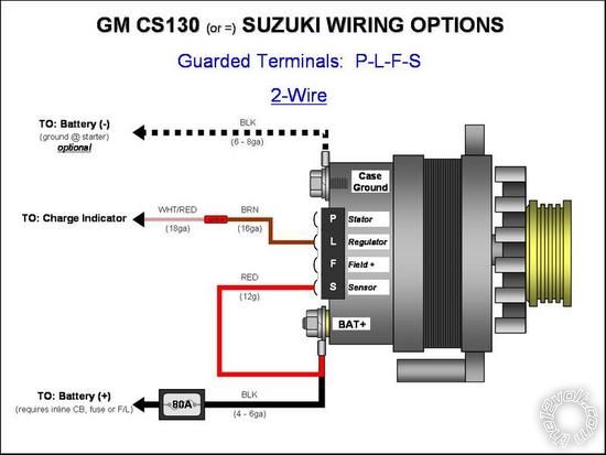
And that alternator does not look like an SL type, it's a PLFS which sounds like it needs an external regulator.
Posted By: alcapon1
Date Posted: November 21, 2011 at 1:36 PM
The thing is I cant find a diagram of a 2 wire/ S-L alternator as everything comes up as a one wire or three, but maybe that is not spacifically what it is called. I think if I knew specifically which type of alternator or an example it would help me out. The L wire to the battery post was suppose to be S, the L is the charge light so ya my mistake.
-------------
wire the world
Posted By: oldspark
Date Posted: November 22, 2011 at 2:45 AM

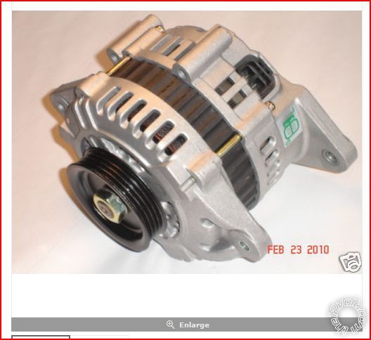
(From spidermarine.com item=101665 Hitachi 12V 110Amp Alternator
But that connector should look like the black one....:

But you may be best going to some alternator place and specifying what you want - ie, spin direction, mounting type, pulley type, etc, though AFAIK Hitachi SLs are generally only up to ~110A.
I did see a big Hitachi over 200A for emergency vehicles (Ford?), but that looked like a single-wire type.
For HO alternators, the pulleys are usually serpentine belt, but they have various groove options (eg, 4, 5, 6 grooves)
Posted By: alcapon1
Date Posted: November 22, 2011 at 4:31 AM
I will post pictures of the install and I might even order the same one from that link. Awesome!
-------------
wire the world
Posted By: alcapon1
Date Posted: November 22, 2011 at 4:49 AM
-------------
wire the world
Posted By: alcapon1
Date Posted: November 22, 2011 at 5:20 AM
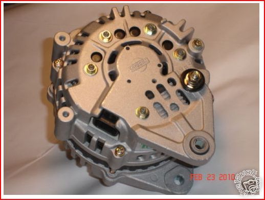
I found this alternator and it has the same connector, its an infinity M30 alternator. I am just wondering about the connector.... do I just tap right into those 2 outputs or do I buy the harness that fits it and just wire it up? Is it really that simple of just hooking up the power wire, the S wire, and then the L wire. Maybe I am over thinking this.
-------------
wire the world
Posted By: oldspark
Date Posted: November 22, 2011 at 6:50 AM
Having said that the connector is irrelevant, one thing I like with that Hitachi connector - as well as other "similar" connectors used by others - is that they use "standard" 6.3mm (1/4") spade terminals.
Hence it is usually easy to connect without the proper plastic-encased terminals, albeit perhaps not as secure. (Most connectors have a locking tab which must be pushed in or lifter to disconnect.)
However I have never bought a new alternator. Mine have always been purchased from auto-wreckers (hence $35-$45 instead of 5 to 10 times that $amount), and I ensure I grab the matching connector.
Actually with alternators, I now try to grab the connector with enough cable to make it to the battery+ for the S terminal, and L terminal to the appropriate point in the vehicle's standard harness if possible.
That saves at least one cable extension (usually soldered and shrink-wrapped), though I have been intending to make a "universal" interface using a 3-ternimal "pi" or |_| spade connector so I can have a standard interface and then make up individual alternator connector to "pi" spade connector adapters for quick substitution of various alternators.
[ The 3rd terminal is a spare - eg, in case I ever use an SIL (Sense, Ign +12V, & L) type. (And with the single _ terminal being for the L (charge-Lamp) in case the other two | | get swapped, hence not damaging the L circuit.) ]
And yes, with the SL types, it is "merely" the always required & present big +12V "power" wire to the battery usually labelled B or B+ - often with a fuse (near the battery end); the GND via casing to the engine; S direct to the battery +12V (else B/B+ is imitating a single-wire D+ type), and L to the charge lamp of the vehicle.
Note that almost all alternators need the L-circuit connected. Traditionally that was to provide a trickle or tickle current to the rotor (through te charge-Lamp or other lamps) to ensure current generation, though some alternators simply require it to operate the regulator even if the alternator has its own "tickle" method.
In traditional "tickle" charge-Lamp alternators/regulators, the alternator might charge without the charge-Lamp bulb (or L trickle current) thanks to "residual" rotor magnetism, but that may not always occur.
Resistors can be used instead of lamps. Lamps are usually 2W to 3W (~200-250mA), and several bulbs to a total of maybe 1A or 2A might tbe involved, but often trickle currents as low as 10-20mA are sufficient, hence maybe a 560 Ohm resistor (with optional LED).
And don't forget, the electrical connections are probably the easiest part.
Getting the correct direction (clockwise or anti-clockwise) and suitable mounting flanges and spacings - and pulley type & offset - are all variables if the alternator fit is not known.
Don't just buy any alternator because the connectors or type is right.
Also, it may be that HO isn't readily available as an SL type (they seem to be D+ types else with external regulators. In that case, a choice has to be made, but hopefully you and others see the versatility of the "S" types as their "Sense" can be easily converted to a D+ type, or extended to sense a remote battery, or the alternator tricked into producing a higher output voltage with the inclusion of a series voltage dropping device (eg, a diode). That might be overkill for some systems, but it is nice as a "universally" applicable alternator.
PS - use a text editor for your replies, else deleted the unwanted formatting text. Use "Preview Post" before submitting (Post Reply) to check.