crossover design for dipole rears
Printed From: the12volt.com
Forum Name: Car Audio
Forum Discription: Car Stereos, Amplifiers, Crossovers, Processors, Speakers, Subwoofers, etc.
URL: https://www.the12volt.com/installbay/forum_posts.asp?tid=42203
Printed Date: June 03, 2024 at 4:49 AM
Topic: crossover design for dipole rears
Posted By: stevdart
Subject: crossover design for dipole rears
Date Posted: November 03, 2004 at 8:46 PM
This isn't a car audio question but I trust and respect the pro's on this forum so here's my project. I'm building rear surround speakers for home audio and have decided on using the dipole type for my older Pro Logic receiver. This pair of speakers will each have a small woofer and tweeter on front and back in a mirror image arrangement. I need some guidance in building a crossover for each of them. I already bought the woofers and am looking at getting the tweeters. The ports are already purchased. Parts list: woofers (4) ......... Tweeters (4) _(besides low cost, selected for their small size).......... ports are 1" x 4", to be cut, and the crossover components will also come from PartsExpress. From what I've read about the ProLogic receivers, the sound to the rears is a limited frequency response of about 100 Hz to 8000 Hz, and my Yamaha amp gives each speakerbox 20 watts @ 8 ohms. The THD is relatively high to the rears compared to the main and center speakers, so high quality components wouldn't be needed here.....and so I think this is a good way to try making crossovers for the first time. DYohn told me recently that I should reverse polarity of the opposing sides, and highpass the front speaker at about 250 Hz , so I have purchased caps for a first order highpass. I will need to purchase the rest of the components for the crossovers. The diagram below shows an example of a second order crossover. I used that as a guide for my working-model diagram below it which includes the second set of opposing speakers. 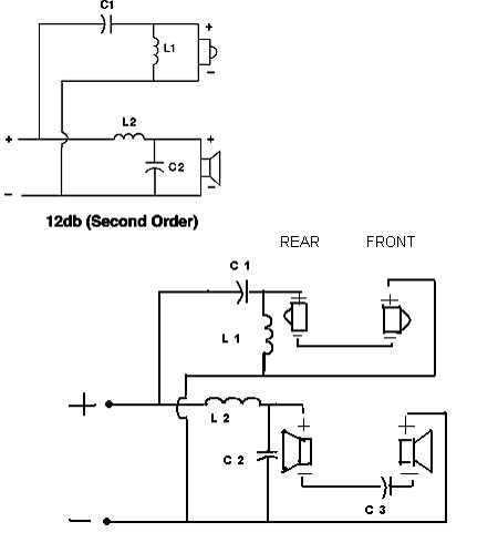
C3 represents the 250 Hz highpass filter. I bought these caps so that I could parallel two to each front woofer for a total of 160 uF to highpass at 250 Hz at 4 ohms. The crossover should be at 3500 Hz. I need to kow this stuff: 1 Would the crossover work as shown in my diagram? 2 Can I put the 250 Hz highpass where it shows in the diagram? 3 Can I use one crossover for each speaker box (as shown)? 4 How do I determine the final impedance of the speaker box with these speakers? And how does the crossover affect the final impedance? When I started this, I thought I would get by using only the woofers, but their range is only to 5000 Hz. That's why I bought them as 4 ohm woofers to be series-wired to an 8 ohm load. Now I don't know how adding 6-ohm tweeters and a crossover will affect the total impedance. 5 Do I figure crossover values on the total of the series-wired speakers, such as at 12 ohms for the tweeters, and at 8 ohms for the woofers? I already figured C3 at 4 ohms because it affects only the front woofer. ------------- Build the box so that it performs well in the worst case scenario and, in return, it will reward you at all times.
Replies:
Posted By: haemphyst
Date Posted: November 03, 2004 at 11:55 PM
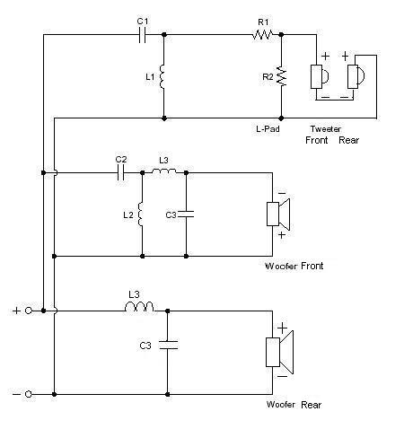
Here is how I would do it...

The answers to your questions -
1. No
2. No
3. Yes
4. Won't be easy. Something like 4 ohms below 250Hz, 2 ohms 250Hz to 3500Hz, and 10 ohms 3500Hz and up. If you were to add a 1 or 2 ohm (10 to 20 watt) resistor in series with the whole enclosure (in the speaker wire between the receiver and speaker) you can bring those resistances up to a more realistic load for your receiver.
5. See diagram and answer 4.
These values are pretty exact, and provide/allow some fashion of impedance control. The values are a little wierd, but you will likely not affect performance much if you stick ACAP to the listed values. Do not leave the tweeter pads out, unless you like it REALLY bright. The tweeeters will be about 4dB hotter than the woofers. ------------- It all reminds me of something that Molière once said to Guy de Maupassant at a café in Vienna: "That's nice. You should write it down."
Posted By: kfr01
Date Posted: November 04, 2004 at 12:02 AM
haemphyst, what crossover design program do you use?
-------------
New Project: 2003 Pathfinder
Posted By: haemphyst
Date Posted: November 04, 2004 at 7:45 AM
The old-school JBL SpeakerShop. It has crossover and enclosure modules, supporting 1st thru 4th order, in 2 way and three way versions. You can add drivers to the database. PR, Band-pass(4th, 6th, and 7th order), sealed, and vented enclosures are supported. Pretty good, all-in-all. A little tweaky in 2K and XP, but only when changing window size...
-------------
It all reminds me of something that Molière once said to Guy de Maupassant at a café in Vienna: "That's nice. You should write it down."
Posted By: stevdart
Date Posted: November 04, 2004 at 8:17 AM
Haemphyst, thank you for the input. In the diagram you show, first with the tweeter: it looks like I should just series-wire the rear tweeter to the tweeter shown?
The bottom woofer looks like a highpass crossover because it has the same allignment as the tweeter. Is it right? It should lowpass at 3500 Hz.
The middle woofer represents the front woofer, which is to be highpassed at 250 Hz and lowpassed at 3500 Hz?
Do I reverse the polarity shown on the center woofer so that it is out-of-phase with the opposing woofer? This is a rough outline of the dipole arrangement: 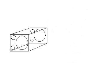
------------- Build the box so that it performs well in the worst case scenario and, in return, it will reward you at all times.
Posted By: haemphyst
Date Posted: November 04, 2004 at 8:39 AM
Yes, the second tweeter is series wired with the first.
Yes, the bottom woofer is HP at 250Hz. Actually, what you need is the middle woofer to be the front one, as it is bandpassed at 250 to 3500, so that is good. I was wrong with the bottom one, it should be lowpassed at 3500, and the amp will "high-pass" it at 100Hz. Use L3 and C3 values in the same places, but on the bottom woofer. I copy/pasted the wrong components - sorry, and good catch!
You can do the phase thing, if you like, but for my money, it will make placement far more critical, as far as spacing to boundary walls (rear wall, specifically), and I personally would try it both ways, to see which worked best in my application. I am not saying DYohn is wrong, I'm just saying try it both ways to see which works better for you. Also remember, if you change the phase on the rear woofer, also do it with the rear tweeter, so as to avoid possibly unacceptable phasing and lobing issues.
-------------
It all reminds me of something that Molière once said to Guy de Maupassant at a café in Vienna: "That's nice. You should write it down."
Posted By: stevdart
Date Posted: November 04, 2004 at 8:55 AM
Okay, thanks. I'll change the values on the bottom one (rear woofer) to L3 and C3, and reverse the configuration so that the coil is in parallel and the cap is in series. On the middle bandpass figure (front woofer), is the order of components shown correct, then? The cap C2 is before the coil L3. ------------- Build the box so that it performs well in the worst case scenario and, in return, it will reward you at all times.
Posted By: haemphyst
Date Posted: November 04, 2004 at 9:45 AM
Yes... that information is correct.
-------------
It all reminds me of something that Molière once said to Guy de Maupassant at a café in Vienna: "That's nice. You should write it down."
Posted By: DYohn
Date Posted: November 04, 2004 at 10:25 AM
Looks like you guys are getting this one hammered out. Like I said, the Xover design can be tricky... :) A couple of points: If the speakers are in phase, it is a "bipole" system. Bipoles are very good in AC3 or 7.1 side fill systems with lots of side ambience. Wiring them out of phase is what makes it a "dipole." Using true dipoles is really only satisfactory with Dolby Pro Logic (or older) surround systems. My suggestion for keeping one of the woofers highpassed at about 250Hz in relation to the other creates a modified dipole, where one woofer operates as a monopole below the high pass frequency. Its bass information will not be diffused and will remain in phase. This is more satisfactory with modern surround schemes that include more direct program information in the rear channels. But I agree, try it both ways and see what works best. Also, you don't necessarily need two tweeter; lots of folks build dipole bass systems and mount one tweeter only. Here's an interesting and very powerful calculator for dipole bass systems. Here's a good crossover schematic for a THX certified dipole system. ------------- Support the12volt.com
Posted By: stevdart
Date Posted: November 04, 2004 at 10:46 AM
Thank you to two of the best. I think I can get on the right track with this thing now. :)
-------------
Build the box so that it performs well in the worst case scenario and, in return, it will reward you at all times.
Posted By: stevdart
Date Posted: November 05, 2004 at 9:08 AM
My hurdle now is verifying the crossover cap and coil values with the ones haemphyst came up with using his program. For instance, the value for the tweeter crossover at 3500 Hz: C1 and L1. Instead of using a 12 ohm impedance for the series-wired 6 ohm tweeters, the program seemed to have used about 17.5 ohms for the tweeter impedance. What is the program looking at that I wouldn't know if I used a calculator or a chart? The other cap and coil values listed don't match with the chart or calculator, either, but not off by as much. Can anyone verify? haemphyst, do I go with what your program says? Is it taking into account the differences in impedance with the individual speakers as talked about earlier ("These values are pretty exact, and provide/allow some fashion of impedance control.")? Just want to be sure before I order the parts. Thanks. ------------- Build the box so that it performs well in the worst case scenario and, in return, it will reward you at all times.
Posted By: haemphyst
Date Posted: November 05, 2004 at 9:24 AM
When you use a 12dB crossover, the cap value is NOT the same as if you were just using a 6dB crossover slope. Those values are correct.
Update - This is wierd. I just used the calculator, and it does seem to be using the 17 ohm value, just as you said. DYohn, does this crossover calculator use a DCR, or does it use the dynamic impedance when figuring. A 17 ohm peak for a 12 ohm driver would not be out of the question...
I can say that I have used this software MANY times, with VERY pleasing results. There is impedance compensation allowed for in this software - I cannot say for certain that is was allowed for on the tweeter portion, as it did not ask for the inductance of the VC - actually, it DOES ask, I just couldn't provide it, as it was not supplied to me... The woofer sections ARE impedance corrected, as you can see, I did supply the inductance values for the software.
As to which software is correct? That will really be a tough call, as I do not know which one is using AC impedance or DC resistance. The rest of the values are correct, so, personally, I would hold my tongue just right, and go with the JBL. Those small value caps and coils shouldn't cost more than a few bucks, total, and should be easy enough to swap out, if you get a crappy result.
I wish I had a more concrete answer for you, but I don't. Let me know how it all comes out.
-------------
It all reminds me of something that Molière once said to Guy de Maupassant at a café in Vienna: "That's nice. You should write it down."
Posted By: DYohn
Date Posted: November 05, 2004 at 9:25 AM
Cap and coil alues don't have to match exactly. Within 10% is more than fine. I also usually have a few small value caps handy that can be soldered in to make fine tuning adjustments when building a crossover as you can never be 100% certain using any calculator. Remember that calculators use ideal values and every speaker, cap and coil is different; none are ideal! Also, surround speakers are not nearly as critical as mains in terms of having a dip or peak at the crossover point. I doubt very much you'd hear it if it was there. The JBL program is very good and accurate. I am not certain if they use dynamic compensation or straight DCR, but I say trust it and use it as a basis for the circuit then make fine tuning adjustments if necessary. ------------- Support the12volt.com
Posted By: stevdart
Date Posted: November 05, 2004 at 9:35 AM
Done deal. I'll use the values you listed and maybe pick up some spare parts when I order. Thanks for the replies, gentlemen...and I'll let you know the results when it's all said and done. ------------- Build the box so that it performs well in the worst case scenario and, in return, it will reward you at all times.
Posted By: stevdart
Date Posted: November 05, 2004 at 11:40 PM
|