Grounding confusion
Printed From: the12volt.comForum Name: Car Audio
Forum Discription: Car Stereos, Amplifiers, Crossovers, Processors, Speakers, Subwoofers, etc.
URL: https://www.the12volt.com/installbay/forum_posts.asp?tid=80609
Printed Date: May 04, 2024 at 9:33 AM
Topic: Grounding confusion
Posted By: 12vdeej
Subject: Grounding confusion
Date Posted: July 22, 2006 at 2:12 PM
Replies:
Posted By: stevdart
Date Posted: July 22, 2006 at 4:22 PM
-------------
Build the box so that it performs well in the worst case scenario and, in return, it will reward you at all times.
Posted By: 12vdeej
Date Posted: July 23, 2006 at 6:00 AM
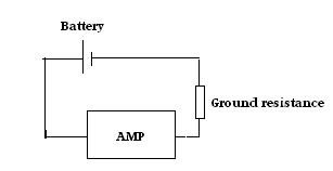
The explaination you gave would surely be for the output current, seeing as you are using the output votlage and the load resistance to calculate the current? I am talking about the input current draw. The diagram below shows the grounding resistance modelled as a resistor. Seeing as the amp is in series with the 'grounding resistor', the maximum current the amp can draw is determined by the sum of the resistance of the ground and and the amp's own impedance. Hopefully this helps to explain the problem more clearly.
Posted By: stevdart
Date Posted: July 23, 2006 at 9:39 AM
Yeah, that's why I try to tackle these kinds of problems. It confuses me, so I have to sort it all out every time. Some day maybe it will come quick and easy.
I think I would have had to first determine power output of the amplifier, then use the voltage at the battery as E to find current draw. The efficiency of the amplifier would have had to be calculated, as well. And it seems reasonable, in a sense, to add the resistance of the ground circuit to the resistance of the device (as you displayed above) to find an answer, but that resistance is not part of the load resistance. It is resistance in a conduit back to the power source.
In all reality, the ground circuit is acting just like a wire...in fact, a wire could replace it altogether. You could have 0.5 ohms resistance in a ground wire run all the way to battery ground just as much as you could have 0.5 ohms of resistance in the chassis itself. Or you could have more resistance than 0.5 ohms. That resistance figure still cannot be used, by itself, as the number for R in an Ohm's Law formula (as you used it in the original post). When something looks reasonable in theory, but obviously makes no sense when you apply logic, you can presume that the theory may not be correct.
If you look at ground resistance as nothing more than "a wire", then think of it as you would think of a wire when determining its responsiblity in affecting power. Here is a quote from DYohn that I saved to file that was written about wire:
Larger wire does not "produce more current flow" nor does it rob anything from anything to use multiple sizes. The LOAD (in this case the amp or the speakers) creates the demand for current flow. Larger gage wires ALLOW more current flow than smaller ones with less HEAT and losses. ANY wire will try and pass whatever current demand is required by the load. The wire does not care. A 36 gage wire will try to pass all 200 amps demanded by a large amplifier if you hook it up that way. It's just that smaller wire will add enough resistance to burn up faster. It is impossible for a wire, any wire, to "produce" current all by itself. Using smaller wire does not "rob your sub of its full potential," this is a myth. Smaller wire is simply a fire hazard.
(edited to add: you smarter ones on this forum, feel free to correct me if I'm off-base with this. it's always a learning experience... ;)
-------------
Build the box so that it performs well in the worst case scenario and, in return, it will reward you at all times.
Posted By: Mad Scientists
Date Posted: July 23, 2006 at 10:59 AM
First off, I suspect most of us don´t have a meter capable of accurately measuring ground resistance. Anyone want to argue that, please post what kind of meter you have. I´ve got a Fluke 88, and well as an 8060 and many others, and they aren´t good enough to directly measure ground resistance.
Besides, circuit resistance itself isn´t our concern.. what we´re concerned with is voltage drop. We can measure voltage drop easily. Thinking about Ohm´s law, voltage drop is determined not only by resistance, but also by current flow. Using the 0.5 ohm circuit resistance mentioned earlier, if this was measured on a circuit powering an LED using 0.020 amps, the circuit drop would be 0.01 volts. Nothing to worry about here. If, however, that same circuit resistance was measured in a circuit powering a headlight using 8 amps, then the voltage drop on that circuit would be 4 volts.. meaning the headlight would only be seeing around 10 volts instead of the full 14 volts that the alternator is pulling out. This is why relays are a good idea for aux lighting as well as upgraded headlights.
Wire size will also determine voltage drop.. smaller wires have a greater resistance per foot than larger wires. Undersized wires will restrict current flow through them, this translates into voltage drop. Does your amp work better at 14v or at 10v.
I don´t like to see more than 1.0v drop on the starter wires.. that means that circuit resistance for those wires at 200 amps can´t be more than 0.005 ohms.
If you have a question or aren´t clear on something, please post.
Jim
Posted By: 12vdeej
Date Posted: July 23, 2006 at 2:55 PM
Steve, in your example where you replace the chassis with a wire (essentialy the same as where i replaced it with a resisitor), would you agree that if you have a 14V power supply (the alternator) and a wire/grounding resistance of 0.5ohms the maximum current that can flow through that wire is 28 amps. I would like to have that confirmed, or i definately do not understand what is going on! If i am correct, then seeing as the ground is connected in series with the amp then the maximum current that the amp could recieve would be 28 amps (which realistically would not happen as the amp itself would have to have zero resistance).
Jim, I agree that higher resisitance ground will cause a greater voltage drop in the chassis so that there is less voltage available for the amp, but you havn't mentioned the fact that the higher resistance will also reduce the current flow through both the chassis and amp (seeing as they are connected in series). Another way of phrasing my question is 'can an amp that draws 100Amps at full power run in a car that has a grounding resistance of 0.5 ohms?' if the answer is no then no further explaination is required, but if it is yes then further explaination is definately required! Thanks again for trying to answer this difficult-to-explain problem
Posted By: Mad Scientists
Date Posted: July 23, 2006 at 3:38 PM
"can an amp that draws 100Amps at full power run in a car that has a grounding resistance of 0.5 ohms?"
No.. you are correct; with 14v and a resistance of 0.5 ohms, the circuit current would be 28 amps. Ohm's Law, plain and simple. If you measured 3.2 ohms on your amp circuit but everything worked correctly, then you almost certainly got a bad reading somehow. Measuring voltage drop is the best way to determine if your wiring is ok.
Jim
Posted By: 12vdeej
Date Posted: July 23, 2006 at 6:03 PM
Posted By: stevdart
Date Posted: July 23, 2006 at 7:34 PM
A half ohm of resistance in the chasis ground-to-battery is not uncommon...in fact, it's good. Isn't it? Let's double-check your reckoning by employing some Ohm's Law and logic to a common scenario:
Guy has three amps. Two for subwoofers and one for the mids/highs. Sub amps have loads wired to 2 ohms, and the third amp is working at a 4 ohm load.
There is 1/2 ohm of resistance between the amplifier common ground point and the battery negative terminal. You are saying that with a resistance of that much in the chassis to ground, his system can draw no more than 28 amps of current.
Guy measures voltage of each one of the amps after gains have all been set. The system is set to full power. He wants to find power so that he can determine the draw of current from the car.
- mono amp 1: output voltage is measured at 32 volts. P = E^2 / R says that this amp is producing 512 watts (it's a 2 ohm load). Now, the amp is a class D and is about 85% efficient. To produce 512 watts, the amplifer has to use enough current to make up for its waste factor. Figuring in 15% for heat waste, this amplifier needs to consume enough for 602 watts of power to make 512 watts. With battery voltage at 14, I = P/E tells us that this amp will demand 43 amps of current.
- mono amp 2 is the same, using 43 amps of current.
- 4 channel amp is measured at 38 volts. It is 60% efficient. P = E^2 / R says that with this amp's 4 ohm load its power output is 361 watts. With a waste of 40%, it needs enough current to make 505 watts. Battery voltage is 14 volts, so the current needed is 36 amps from the battery ( I = P/E ).
This is not an unreal situation. This is a big, loud system but not all that uncommon. And assume that these power numbers are real because the HO alternator keeps up with the demand. 512 + 512 + 361 = 1385 total watts for this system at full power.
To get this power, there is a draw of 122 amps from the car (43 + 43 + 36).
How do you get this power if a chassis ground of 0.5 ohms is limiting the power output that much? At a maximum limit of 28 amps, there would not be enough power for just the 4 channel amp alone. 28 X 14 = 392 (P = I X E). You are saying that this system cannot produce any more than 392 watts (and actually quite a bit less than that as we figure the amps' heat waste factor).
The quote above says that a wire (or the chassis, if you will) will try to pass whatever current is demanded by the load. The loss due to resistance does have an effect, but not to the extent you are saying it does. Here is a calculator that will help determine losses of resistance in the circuit: https://www.h-o-alternators.com/TechCalcs/voltdropthroughsystemhoalt.swf
Here's another: https://www.h-o-alternators.com/TechCalcs/wirepowercalculatorhoalt.swf
-------------
Build the box so that it performs well in the worst case scenario and, in return, it will reward you at all times.
Posted By: haemphyst
Date Posted: July 23, 2006 at 11:46 PM
The one half ohm ideal is an ADDITIONAL half ohm in the entire circuit - it's not a stand-alone resistance. The AMPLIFIER POWER SUPPLY is the other part of the resistance. They are two resistances in series.
So you have amp power supply, PLUS ground return resistance to consider - they are additive. When the amplifier power supply is running WFO, the resistance is VERY LOW, compared to (and relative to) the return resistance. It HAS to be, or more power would be dissipated in the return than in the PS, and we know this is not the case, except in very poor installations...
Your return resistance only serves to reduce the power available for the power supply of the amplifier to pass on to the output load.
If you look at it this way, a 1/2 ohm return resistance, at 14.4 volts, would dissipate 7.2W at a 100A current draw, including all of the connections. That is a very good number. To increase that number to 3.2 ohms, as you had before, at a 100A draw, your power loss in the cables (and connections) would be 46W. A lot wasted, but still not a lot in the overall scheme of things, but due to the additional voltage drop, your amp will need to pull more current, to make the same amount of power. The additional draw requirements would be dynamic, with more power needed (additional) as you try to put more power out.
Hope that helped...
-------------
It all reminds me of something that Molière once said to Guy de Maupassant at a café in Vienna: "That's nice. You should write it down."
Posted By: Mad Scientists
Date Posted: July 24, 2006 at 8:32 AM
Ignore all the audio equipment for a moment.. reduce it to the basics. You have a V of 14.4vdc, a circuit resistance of 0.5 ohms, apply ohm's law and calculate current.
Voltage = amps * resistance
14.4 = ? * 0.5
14.4 / 0.5 = 28.8 amps
Looking at the simulations that stevdart linked; 500 feet of 10 g is approximately 0.5 ohms. Enter those numbers into one of the wire points and see what happens to all the numbers.
https://www.powerstream.com/Wire_Size.htmUntil you consider that the 0.5 ohm reading is incorrect, Ohm's Law states that you can't push 100 amps with 14.4 volts through a 0.5 ohm resistance.
https://ourworld.compuserve.com/homepages/Bill_Bowden/ohmslaw.htm
Jim
Posted By: stevdart
Date Posted: July 24, 2006 at 3:20 PM
I showed that it is illogical to think that a mere 1/2 ohm of circuit resistance is going to reduce a car's sound sytem, no matter how big it is, to less than 300 watts. And I showed that it normally takes a series of Ohm's Law equations, not just one, to find an answer.
haemphyst explained it very well, I thought. I just don't know the actual calculations he used to find the loss value.
haemphyst wrote:
If you look at it this way, a 1/2 ohm return resistance, at 14.4 volts, would dissipate 7.2W at a 100A current draw, including all of the connections. That is a very good number. To increase that number to 3.2 ohms, as you had before, at a 100A draw, your power loss in the cables (and connections) would be 46W. A lot wasted, but still not a lot in the overall scheme of things, but due to the additional voltage drop, your amp will need to pull more current, to make the same amount of power. The additional draw requirements would be dynamic, with more power needed (additional) as you try to put more power out.
-------------
Build the box so that it performs well in the worst case scenario and, in return, it will reward you at all times.
Posted By: Mad Scientists
Date Posted: July 24, 2006 at 4:25 PM
If you would, please explain when you use the simulator you provided
https://www.h-o-alternators.com/TechCalcs/voltdropthroughsystemhoalt.swf
and change the specs of the ground wire on the battery to 500 feet of 10 gauge wire (to simulate a 0.5 ohm resistance)
Move the volume to show an amplifier power without losses of 250
and read an amplifier power after losses of -27, and a total voltage loss of 15.275v, and a voltage at the amplifier terminals of -1.475v. Moving the volume slider around, the best output I can get is 56 watts. That's with an amplifier power without losses of 100+.
Explain to me what I'm doing wrong. I used your simulation, I added 0.5 ohms of resistance on the ground path, and the system doesn't work.
Jim
Posted By: Mad Scientists
Date Posted: July 24, 2006 at 4:45 PM
stevdart wrote:
I showed that it is illogical to think that a mere 1/2 ohm of circuit resistance is going to reduce a car's sound sytem, no matter how big it is, to less than 300 watts. And I showed that it normally takes a series of Ohm's Law equations, not just one, to find an answer.
haemphyst explained it very well, I thought. I just don't know the actual calculations he used to find the loss value.
haemphyst wrote:
If you look at it this way, a 1/2 ohm return resistance, at 14.4 volts, would dissipate 7.2W at a 100A current draw, including all of the connections. That is a very good number. To increase that number to 3.2 ohms, as you had before, at a 100A draw, your power loss in the cables (and connections) would be 46W. A lot wasted, but still not a lot in the overall scheme of things, but due to the additional voltage drop, your amp will need to pull more current, to make the same amount of power. The additional draw requirements would be dynamic, with more power needed (additional) as you try to put more power out.
I don't know how Haemphyst calculated it either.. I'd be interested in see the calculations. If I was doing calculations for sizing that resistor wattage I'd do something like;
watts = volts * amps
A 0.5 ohm resistor with 100 amps pushing through it is going to be dropping 50 volts.
watts = 50 volts * 100 amps
watts = 5000
Jim
Posted By: stevdart
Date Posted: July 24, 2006 at 6:50 PM
I can't answer that because you are going on the presumption that the Ohm's Law formula you used is correct for the situation, as you are equating 1/2 ohm circuit resistance to 28 volts (the power/loss demo equates this long wire to a loss of 28 volts). Actually, you were referring to 28 amps previously...
Mad Scientists wrote:
you are correct; with 14v and a resistance of 0.5 ohms, the circuit current would be 28 amps.
That's the number (28) you were looking for when you arrived at 500 feet of 10 gauge wire in that application. I'm not studied in the electrical field, but I'm a logical person. I have measured loss in wiring and circuits...and I use my logic to conclude that 1/2 ohm resistance through the chassis doesn't equate to a whopping 500 feet of 10 gauge wire.
This is just a question I've never seen pop up, maybe because the premise of it is so far-fetched. The original author of this thread saw for himself that there was little, if any, discernible difference after he upgraded the ground. I have a lot of studying to do to find the actual reason that you and he believe that 1/2 ohm circuit resistance makes such a major impact. But I can see that you are still using this resistance factor alone in the equation. You have to consider this: you said to forget the sound system in this. But this is the point: without the amplifier(s) there isn't a load and consequential demand for amperage, and therefore no circuit. Without a circuit there is no voltage drop or loss due to circuit resistance.
I think there has to be a series of equations done, not just one. I just don't know what they are yet. And the only thing I can pinpoint that is wrong with your use of the Ohm's Law formula is that you are leaving out the load on the circuit altogether. Even if you add this 0.5 ohms as a resistance factor to the load, the answer doesn't seem to be right. For example, a 2 ohm load with 1/2 ohm added to it makes a much bigger difference than a 4 ohm load with 1/2 ohm added to it. One formula, W = I^2 * R (power loss in watts increased as the square of the current) may have something to do with solving this but I'm not sure how to use it.
-------------
Build the box so that it performs well in the worst case scenario and, in return, it will reward you at all times.
Posted By: Mad Scientists
Date Posted: July 24, 2006 at 9:13 PM
stevdart wrote:
I can't answer that because you are going on the presumption that the Ohm's Law formula you used is correct for the situation, as you are equating 1/2 ohm circuit resistance to 28 volts (the power/loss demo equates this long wire to a loss of 28 volts). Actually, you were referring to 28 amps previously...
I can assure you that I'm not equating 1/2 ohm circuit resistance to 28 volts.. the power/loss demo is flawed. If you take the demo up to about 230 amp without loss you'll see the correct numbers; the voltage available to the amp is around 0.2v and the rest of the voltage is dropped across the 1/2 ohm resistance. It appears that the demo doesn't take into account increased circuit resistance and modify the current accordingly. You can see evidence of this by changing the cable length of the ground cable from 5 feet to 5000 feet and not seeing a change in voltage drop on the other cables, this indicates that circuit current isn't changing.
stevdart wrote:
Mad Scientists wrote:
you are correct; with 14v and a resistance of 0.5 ohms, the circuit current would be 28 amps.
That's the number (28) you were looking for when you arrived at 500 feet of 10 gauge wire in that application. I'm not studied in the electrical field, but I'm a logical person. I have measured loss in wiring and circuits...and I use my logic to conclude that 1/2 ohm resistance through the chassis doesn't equate to a whopping 500 feet of 10 gauge wire.
https://www.powerstream.com/Wire_Size.htm
I linked the chart that gives ohms per 1k foot numbers.. 500 feet of 10 gauge is 1/2 ohm. So is 100 feet of 17 gauge, and 50 feet of 20 gauge. And if you enter each of combinations into the demo, the results are pretty much the same. I'm taking the chart as fact. If you can find something different, let's see it
stevdart wrote:
This is just a question I've never seen pop up, maybe because the premise of it is so far-fetched. The original author of this thread saw for himself that there was little, if any, discernible difference after he upgraded the ground. I have a lot of studying to do to find the actual reason that you and he believe that 1/2 ohm circuit resistance makes such a major impact. But I can see that you are still using this resistance factor alone in the equation. You have to consider this: you said to forget the sound system in this. But this is the point: without the amplifier(s) there isn't a load and consequential demand for amperage, and therefore no circuit. Without a circuit there is not voltage drop or resistance loss.
I imagine that the reason the OP didn't see much difference was at least partially because he wasn't using a meter accurate enough.. as I mentioned earlier in the thread, I have a number of high dollar meters, and I don't feel they are accurate enough for this particular measurement.. that's why I always suggest voltage drop measurements.
When I said to forget the sound system in this I meant to ignore the audio side of it.. don't worry about trying to calculate power usage by measuring output etc, etc. For an example, let's say the amp draws 100 amps WFO. We can calculate apparent resistance by dividing 14v by 100 amps. To the battery, the amp looks like a 0.14 ohm resistance. If you add a 0.5 ohm resistance to the circuit, then total circuit resistance becomes 0.64 ohms. Maximum circuit current then becomes 14 volts divided by 0.64 ohms, or 21.87 amps. You'll never see more than 21.87 amps in that circuit.
stevdart wrote:
I think there has to be a series of equations done, not just one. I just don't know what they are yet. And the only thing I can pinpoint that is wrong with your use of the Ohm's Law formula is that you are leaving out the load on the circuit altogether. Even if you add this as a resistance factor to the load, the answer doesn't seem to be right. For example, a 2 ohm load with 1/2 ohm added to it makes a much bigger difference than a 4 ohm load with 1/2 ohm added to it. One formula, W = I^2 * R (power loss in watts increasing as the square of the current) may have something to do with solving this but I'm not sure how to use it.
https://www.angelfire.com/pa/baconbacon/page2.html
For watts, use Watts = volts * amps.. it's much easier. WRT your 2 ohm 4 ohm examples, are you talking about audio or power? A 1/2 ohm increase to 2 ohms is a 25% increase, with 4 ohms it's only a 12.5% increase.
Ohm's Law is easy.. you're way over thinking this. The best way I could demonstrate this here would be to recommend to you to get an old style headlight.. one of the large retangular ones would work good. Ohm it out; it'll probably be close to 1/2 ohm or less. Wire the headlight into the power circuit of one of your amps.. you could probably open the circuit at the fuse and install it there. You've just introduced a 1/2 ohm resistance into your amp circuit.. see what happens.
Jim
Posted By: Mad Scientists
Date Posted: July 25, 2006 at 6:27 AM
Correction.. a standard 60 watt headlight is going to be around 2 ohms.. so parallel a couple to get 1 ohm if you'd like.
Jim
Posted By: 12vdeej
Date Posted: July 25, 2006 at 4:43 PM

Posted By: Mad Scientists
Date Posted: July 25, 2006 at 6:00 PM
Personally, I think the reality is that the measurement isn't accurate.. but if you were so inclined you could do the 'hook a headlight into the amp power circuit' trick I mentioned earlier in the thread. That'll put a 2 ohm resistance into the power circuit; I promise you'll see the difference.
I have an electronics degree, and 20+ years experience, more than half of which is automotive electrical/electronics; ASE certs and all that. Currently I work for a state agency doing electronics, and moonlight for a local university doing, among other things, systems automation.
I'll be the first to admit I don't know it all.. the more I learn, the more I realize how little I know.
But I do know a little.
Jim
Posted By: Mad Scientists
Date Posted: July 25, 2006 at 7:57 PM
Well.. if you have any questions, just ask. Working purely in theory makes it more difficult, which is why I suggested the headlight mod; hands-on beats theory every time from an understanding perspective.
Jim