This is a pictorial for the installation of a basic run/stop remote starter (Prostart) in a Canadian 2009 Pontiac Vibe (may be the same for the 2009 Matrix). I'm putting this here because most of the other wiring diagrams around are related to US vehicles and are not the same. I almost cooked my DTR module using the color codes in other posts. For this install I removed most of the dash (I have pictures if someone needs them). I probably could have gotten away with just taking off the bottom left panel and the lower steering column cover, but that leaves not much room for accessing the wires etc...
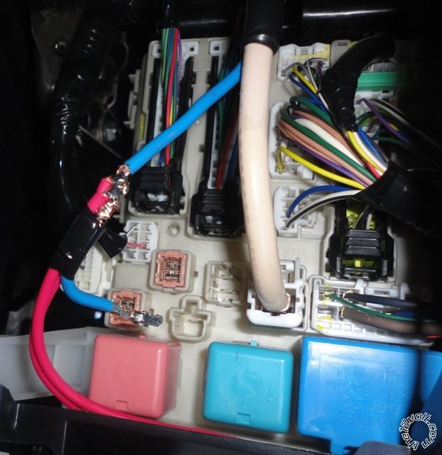
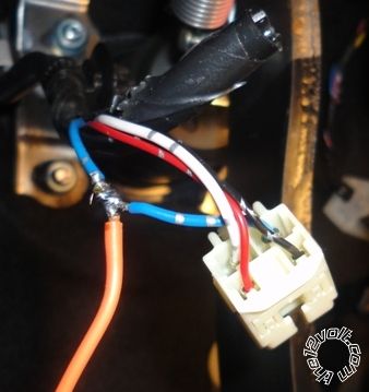
1. This is the first connection (the two +12V power wires from the R/S both soldered to this heavy blue wire (behind the bottom left dash panel)
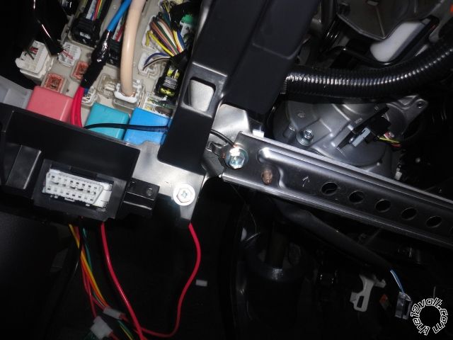
2. Second connection - ground wire from R/S wrapped around this screw.
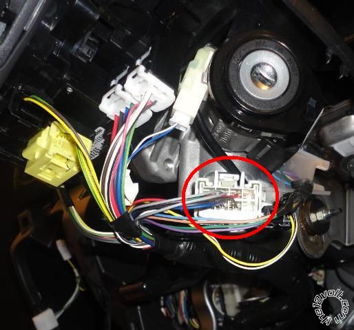
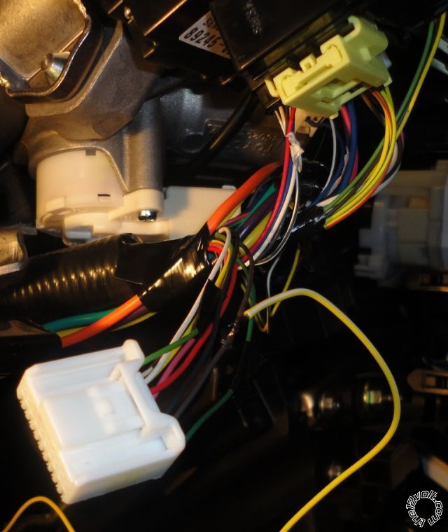
3. Picture of the ignition harness.
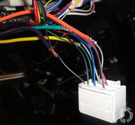
4. Splicing into the ignition harness. Careful here, there's two black starter wires joined together (not two separate wires as some wiring diagrams suggest). Other's match up good.
5. Brake Wire easy one
6. Tach Wire to Diagnostic Connector
7. Parking Lights, careful here! Color is not green as seen in some posts. Also this is a low logic level trigger so you have to setup your R/S to do a - pulse here to turn the lights on, not +. I heard if you try to put the +output from the R/S into here it'll fry some of your car's electronics.

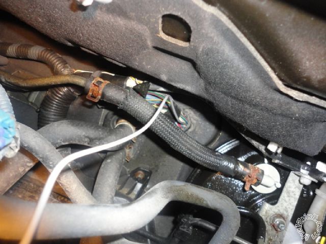
8. Hoodpin switch wire going through firewall. Use a blunt coat hanger to push though from the engine side.
Thats it. After this I programmed the tach level. Then closed the hood. My car has some anti-theft stuff in it so it requires a bypass (which I don't have yet - it's in the mail). So you need the -while running wire from the R/S left hanging for when you get that part. At this point, if the key is in the ignition (off position) the car will start no problem from the remote. If anyone wants, let me know and I'll send/post pics of the PKall bypass install and/or the dash removal.
Thanks,
Richard - Newfoundland
Yes please sendme..some.pics of bypass install. Thanks
-------------
losminos n.c
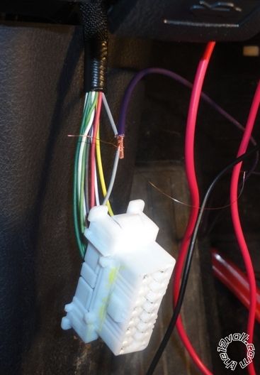
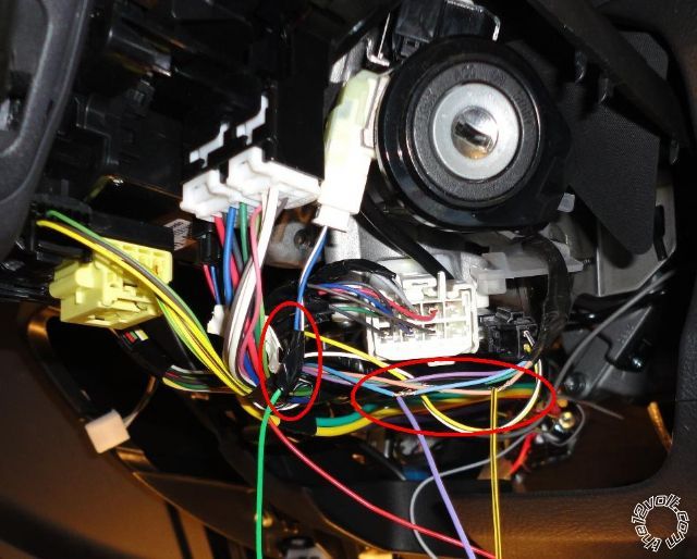
OK, here's the picture of the bypass(RX and TX)and the key sense wire which come from the bypass and need to go to the car's security harness at the ignition key hole (haha).
You can see in the pic, the thin yellow/black (TX) and the PURPLE / white (RX) come up from the PKALL bypass (off screen) and attach to the beige and blue from the harness that goes to the back of the lock cylinder. I had these backwards at first and it didn't work. The green keysense wire goes to the 2-wire plug/harness on the left, blue wire I think.
The whilerunning wire goes to the remote starter's whilerunning wire. And finally for my install (one way without D2D) you have to cut the wires as it says in the instructions and connect +12V and ground which I just took +12V from the ignition harness (not seen clearly in the picture). I used the ADS manual referenced in this (https://www.12voltdata.com/viewtopic.php?f=131&t=2541) thread to get the wire colors in the vibe.
Word of advice, never just wrap a ground wire around a bolt. It will eventually break and come loose. ALWAYS use a the proper sized ring terminal. Also, out of curiosity, why does the blue wire in the original picture look like it was pulled out of a harness... or is it just me?
-------------
Kenny
Owner / Technician
KKD Garage LLC
Albany, NY 12205
i think he depinned it, soldered and had intentions of heat shrink tubing it.
-------------
Ted
2nd Year Tier 1 Medical School
Still installing as a hobby...pays for groceries
Compustar Expert
No thank you... haha. For me, its not worth the risk of screwing up the pin to throw some heat shrink on it. Super33 is plenty strong and durable for me.
-------------
Kenny
Owner / Technician
KKD Garage LLC
Albany, NY 12205
Thanks guys, I knew it was a little shotty just to wrap the black ground around the screw (pic#2) especially with this multi-strand wire but I did secure the wire later so it wouldn't move relative to the screw, I figure I'll get 8-10 years out of that connection... Willn't do that next time... Yes in pic #1 I pulled the plastic plug off the spade connector just to make it easier to handle and put it back on after I taped it up.
RN
Honestly, if it's your own vehicle or you have easy access to it I would find a nicer day and fix the ground now. I've seen some pretty nasty things happen because of a ground connection going bad and I would hate to see something get damaged because of it... or possibly leave you stranded some day. It should only take a few minutes to fix but it could end up saving you a world of hurt later.
-------------
Kenny
Owner / Technician
KKD Garage LLC
Albany, NY 12205