remote start, 1990 ford festiva
Printed From: the12volt.com
Forum Name: Car Security and Convenience
Forum Discription: Car Alarms, Keyless Entries, Remote Starters, Immobilizer Bypasses, Sensors, Door Locks, Window Modules, Heated Mirrors, Heated Seats, etc.
URL: https://www.the12volt.com/installbay/forum_posts.asp?tid=101391
Printed Date: May 01, 2024 at 5:16 PM
Topic: remote start, 1990 ford festiva
Posted By: stefanr
Subject: remote start, 1990 ford festiva
Date Posted: January 20, 2008 at 11:15 AM
Hi guys. This is my first time installing a remote start so id like to doubble check on a couple things.
Im installing a viper 5900
These are ths ignition wires i have,
five heavy wires;
white = battery feed
blue/red = accessory (voltage in acc & on)
BLACK/ red = on (voltage in on)
BLACK/ white = ignition feed (voltage in on & start)
BLACK/ blue = start (voltage in start)
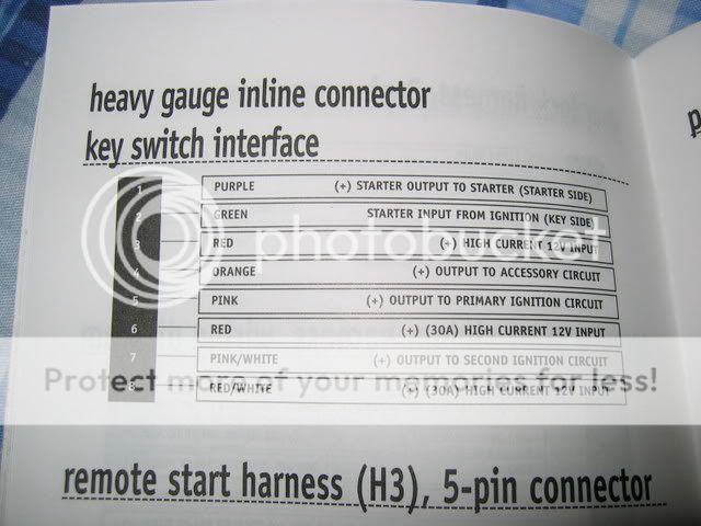
I think i got it all figured out except for purple and green. Do i cut the balck/blue start wire and put purple on the starter side and green on the key side?
Remote start harness // Ignition circuit
Purple ?
Green ?
Red -> White
Orange -> Blue/Red
Pink -> BLACK/ White
Red -> White
Pink/White -> N/A?
RED / White -> White
The only other connection is BLACK/ red = on (voltage in on)Do i need to energize this too? Perhaps using the 2nd ignition wire on the realy satelite?
Replies:
Posted By: GregK
Date Posted: January 20, 2008 at 11:43 AM
What is the vehicle you're installing it in?
Just to make sure you don't have any of the wires wrong.
Posted By: KarTuneMan
Date Posted: January 20, 2008 at 12:08 PM
Remember to include the year make and model of your car when posting.....makes us helping that much easier! Purple and green are for the built in anti grind/starter disable. As it says.... the green one goes to the key side of the cut starter wire and the purple to the other. -------------
Posted By: stefanr
Date Posted: January 20, 2008 at 1:21 PM
1990 Ford Festiva... lol
yea i thought i had the PURPLE / green right.
Now im just not sure if i need to do anything with the BLACK/ red = on (voltage in on)wire. Do i use the 2nd ignition wire here?
thanks guys
Posted By: stefanr
Date Posted: January 20, 2008 at 1:31 PM
Aswell, the power lock outputs on the viper, are they low current for driving relays, or can they be used to run actuators directly. I cant find anything about those outputs in the manual.
I installed power locks way back with a pair of 2 wire actuators and 2 5 pin relays.
Posted By: GregK
Date Posted: January 20, 2008 at 3:53 PM
12 VOLT CONSTANT WHITE (+) IGNITION SWITCH HARNESS STARTER BLACK/ BLUE (+) IGNITION SWITCH HARNESS
IGNITION 1 BLACK/ WHITE (+) IGNITION SWITCH HARNESS ACCESSORY /HEATER BLOWER 1 BLUE/RED (+) IGNITION SWITCH HARNESS
PARKING LIGHTS ( + ) RED / GREEN (+) IN DRIVERS KICK PANEL
DOOR TRIGGER RED / BLUE (-) IN DRIVERS KICK PANEL
DOMELIGHT SUPERVISION USE DOOR TRIGGER, Requires Part #775 Relay HORN GREEN (-) @ STEERING COLUMN HARNESS
TACH YELLOW /GREEN @ IGNITON COIL
BRAKE GREEN/ RED (+) @ SWITCH ABOVE BRAKE PEDAL
The output for the door locks is to drive relays. 250mA draw I believe.
-------------
GDK Electronics
Home theatre & mobile electronics installations
Winnipeg, MB
Posted By: GregK
Date Posted: January 20, 2008 at 3:56 PM
Sorry, first one came out all messed up.
12 VOLT CONSTANT WHITE (+) IGNITION SWITCH HARNESS
STARTER BLACK/ BLUE (+) IGNITION SWITCH HARNESS
IGNITION 1 BLACK/ WHITE (+) IGNITION SWITCH HARNESS
ACCESSORY /HEATER BLOWER 1 BLUE/RED (+) IGNITION SWITCH HARNESS
PARKING LIGHTS ( + ) RED / GREEN (+) IN DRIVERS KICK PANEL
DOOR TRIGGER RED / BLUE (-) IN DRIVERS KICK PANEL
DOMELIGHT SUPERVISION USE DOOR TRIGGER, Requires Part #775 Relay
HORN GREEN (-) @ STEERING COLUMN HARNESS
TACH YELLOW /GREEN @ IGNITON COIL
BRAKE GREEN/ RED (+) @ SWITCH ABOVE BRAKE PEDAL
The output for the door locks is to drive relays. 250mA draw I believe.
-------------
GDK Electronics
Home theatre & mobile electronics installations
Winnipeg, MB
Posted By: stefanr
Date Posted: January 21, 2008 at 12:45 AM
thanks guys
few more questions... on the main harness.. what on earth do i do with the WHITE/ blue remote start (-) activation input.
Also if i hook up the dome supervision... to turn on the dome i would have to ground the neg side.. which is the same as opening up a door.. will this confuse the alarm at all?
also, how should i bypass the clutch switch?
before anyone has kittens about remote start+MTX, the car has a factory neutral gear position switch on the trans that ive wired into the neutral safty wire on the alarm so all is good. the wire showed +12 when in neutral so i reversed the polarity with a relay.
Posted By: brhaugen
Date Posted: January 21, 2008 at 6:21 AM
The WHITE/ blue is used to start the vehicle without the remote.
Use this if you want to start the starter from another device (alarm etc.)
I have hooked these up to a push button under the dash for delivery trucks.
You should be ok hooking up the dome light, I doubt Viper would design something that could set itself off.
You have to test the switch and duplicate it's function with a relay.
PLEASE double and triple check your neutral safety setup.....
Posted By: stefanr
Date Posted: January 21, 2008 at 11:44 AM
brhaugen wrote:
You have to test the switch and duplicate it's function with a relay.
where do i get current to activate the relay when the remote start activates?
Posted By: stefanr
Date Posted: January 21, 2008 at 11:57 AM
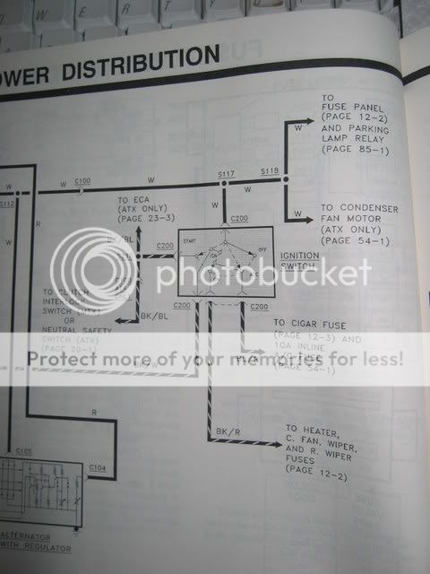
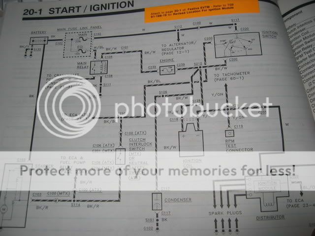
looking at the starting system.. couldnt i cut the starter wire after the clutch switch, and put the green wire on the clutch switch side and the purple wire on the starter side? the starter wire will be past the switch. the clutch switch should still work under regular starting, and anti grind should still work too, i think?
Posted By: stefanr
Date Posted: January 21, 2008 at 12:00 PM
oops, wron picture, can we not edit here?
Posted By: stefanr
Date Posted: January 21, 2008 at 12:06 PM
12 VOLT CONSTANT WHITE (+) IGNITION SWITCH HARNESS
STARTER BLACK/ BLUE (+) IGNITION SWITCH HARNESS
IGNITION 1 BLACK/ WHITE (+) IGNITION SWITCH HARNESS
ACCESSORY /HEATER BLOWER 1 BLUE/RED (+) IGNITION SWITCH HARNESS
if you look at the daigram, if i dont energise the BLACK/ red ON position wire my heater wont run with remote start...
I guess i should use the pink/white wire for this?
|