need advice/comments on circuit
Printed From: the12volt.comForum Name: Car Security and Convenience
Forum Discription: Car Alarms, Keyless Entries, Remote Starters, Immobilizer Bypasses, Sensors, Door Locks, Window Modules, Heated Mirrors, Heated Seats, etc.
URL: https://www.the12volt.com/installbay/forum_posts.asp?tid=118382
Printed Date: January 19, 2026 at 6:36 AM
Topic: need advice/comments on circuit
Posted By: ghostdunks
Subject: need advice/comments on circuit
Date Posted: December 09, 2009 at 8:07 PM
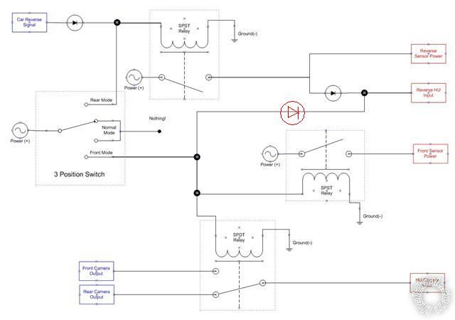
Hi, I'm new to electronics in general but I've installed a couple of headunits in my car, so I'm not completely clueless :) Just wanted to toss a circuit I'm planning to build out there so that people with proper electronics experience can have a look at it and let me know if I'm barking up the wrong tree, etc... Would appreciate any feedback, etc.. Have also included a diagram of the circuit.

4 different systems to be controlled by a single circuit, with 3 different modes(Normal, Rear Mode, Front Mode). 4 systems are:
1) Rear Parking sensors
2) Front parking sensors
3) Rear camera
4) Front camera
Inputs to circuit
a) Car reverse signal(triggered when car is put into reverse gear), 12v signal
b) Front camera output(signal coming from front camera), RCA composite
c) Rear Camera output(signal coming from rear camera), RCA composite
Outputs of circuit
d) Reversing sensors power(12v)
e) Front sensors power(12v)
f) Headunit Reverse signal(12v) - triggers headunit to display whatever is coming from camera input. If not on, headunit will NOT display camera input
g) Headunit camera input. RCA composite
Requirements:
Normal Mode
- Front camera OFF
- Front sensors OFF
- IF car is put into reverse,
- Rear camera ON
- Rear sensors ON
- All front(camera and sensors) OFF
Front Mode
- Front camera ON
- Front sensors ON
- IF car is put into reverse,
- Rear sensors ON
- Front Camera still ON
- Front Sensors still ON
Rear Mode
- All front(camera and sensors) OFF
- Rear camera ON
- Rear sensors ON
Assumptions:
1) Always have power supplied to cameras, and only switch the actual camera output via relay, so that display of image on HU is not dependant on startup time of camera
2) Where it says POWER on diagram, its switched power(ie. only powered when key is in ignition) so it does not drain the battery when car is not in use
3) When in normal mode, I want the default camera signal to be coming from Rear Camera. This is because in the headunit, there is an option to view the camera output WITHOUT the "Reverse HU Input" being triggered, and I want the default input to be coming from the rear camera
Notes on proposed circuit:
1) First diode connected to "Car Reverse Signal" is there so that power from the switch does not feed back into where I'm getting the "Car Reverse Signal" from, eg. car computer so as to lessen chances I fry the computer
2) 3 position switch in circuit shows 4 possible selections as I couldn't find a better shape in Visio! middle two selections are joined in diagram to show they are both connected to same thing...eg. nothing!
3) Even though the POWER shape has an AC wave in it, its meant to be DC 12v.
4) Inputs into circuit are colored blue, and outputs are colored red.
5) Not shown on diagram but I'll be putting quenching/suppression diodes across the coils of the relays
6) I was initially thinking of just using the video switching relay to just switch the video signal, but after a bit more research, I'm thinking I should switch the grounds from each signal as well. I'll be replacing that SPDT relay with a DPDT relay(or just add another SPDT relay to switch the ground).
Replies:
Posted By: Ween
Date Posted: December 09, 2009 at 8:26 PM
Hi,
You need to add a diode on the front mode switch output to the reverse HU input, you'll get a backfeed otherwise.
For your cameras, you may want to make sure the rear one is reverse image and the front one is not.
The relays to power the sensors may be a little overkill, check the current draw of a unit in operation.
Mark
Posted By: ghostdunks
Date Posted: December 09, 2009 at 9:50 PM
Hi Ween
Yup, I already added a diode on the front mode switch output to the reverse HU input, its right there right before the junction where I connect the front mode output to the reverse HU input. Isn't that it, or am I missing something here?
Also sorted with the mirror image with the rear camera and normal image with the front one. Anticipated that one so already accounted for it.
current draw of the parking sensors are rated at 50ma, according to the specs. I ended up using relays mainly because I understand how they work, or think I do anyway... :) If you can suggest another option, I'll be happy to try that out as well.
Posted By: Ween
Date Posted: December 09, 2009 at 10:30 PM
Posted By: Ween
Date Posted: December 09, 2009 at 10:37 PM
Hi,
The added diode is shown above...it's purpose is to block the reverse signal output (from the relay) from activating the front mode circuitry.
If we use convention in the numbering of the relay terminals, then:
positive side of coil is 86, negative side is 85
power input is 30, power output is 87.
Therefore, on the SPST relays, omit the relay and connect 86 to 87.
Mark
Posted By: oldspark
Date Posted: December 09, 2009 at 10:55 PM
Greetings Ghosts & Transcendentals,
Ween means to stop +12V going from the reverse HU input to Front Mode position of the 3-way switch.
Hence a diode in the Front Mode output of the 3 pos switch (pointing to the RHS - same direction as the reverse HU input diode.
The same should/could be be done to the Rear Mode of the 3-pos to prevent the Car Reverse Signal feeding thru to the 3-pos supply.
Hence 2 extra diodes if feed-back or -thru to the supplies is an issue. (Probably not an issue unless the Car Reverse Signal is NOT a typical mechanically switched +12V source - ie, from the gearbox or selector.)
Quenching/suppression diodes across the coils of the relays may not be necessary, but better to be safe, and prevent interference to audio & video.
One diode could do both Front Mode relays, but who cares - one per relay avoids any e-mag transmission etc.
The books will probably tell you to use a matched 75-Ohm impedance (or whatever) coaxial relay for the composite signals, but having seen 75 & 300 Ohm antennae signal get switched with plain switches and relays, I wouldn't worry (and they are several hundred MHz and much weaker signals than ~1Vp-p ~6MHz composite signals).
You may not need to switch the coax shield if it is grounded, but a DPDT relay would be ideal.
(There are solid-state switches (integrated circuits) - but I'd try relays first. Far more robust, and simpler etc.)
You may have a synch-glitch when jumping from one camera to the other, but maybe these days that will be corrected on the next frame...
I congratulate you on your design and especially your description! (If only other questions were so well defined.)
And FYI - I actually prefer the AC source symbol; to me it is obviously a power source. Whether a rectified alternator or battery is irrelevant (provided we know it means DC).
Posted By: tommy...
Date Posted: December 09, 2009 at 11:52 PM
Well spark and Ween...This "jargon" is right up your alley...ey...?! ...I mean that respectfully ...Of Course...! What is your background in electronics(old spark)...Sorry to interupt the post...I just noticed in your profile...There is no mention of it...So curiousity has gotten the best of me...And had to ask...Sorry OP...! And Ween...If i may ask...Your backround also...?
-------------
M.E.C.P & First-Class
Go slow and drink lots of water...Procrastinators' Unite...Tomorrow!
-------------
M.E.C.P & First-Class
Go slow and drink lots of water...Procrastinators' Unite...Tomorrow!
Posted By: oldspark
Date Posted: December 10, 2009 at 12:34 AM
Sorry above - I missed Ween's 2 replies; hence it seems out of sequence.
And Tommy - how dare you! Have you no sensitivity to peoples' private lives?!

Hmmm - not too sure what to put....
Jack of all, Master of many?
I had my education interrupted by a 4 year injuneerink degree. (Started as electronics but got cheesed off & I majored in electrical.)
I had an interest in electronics etc and - because I didn't know any better - I often did the impossible. (Unfortunately that habit continued even after my degree.)
I've been involved in various fields & industries including automotive, military, legal, social - but now tend to be somewhat anti-social.
My last employment ended several years ago - a telecomms company - varied jobs from security, OH&S, systems management, power, product exits.
Since then I've probably spent most time trying to bring automotive & political) hobbyists into the new millennium.
And Tommy - how dare you! Have you no sensitivity to peoples' private lives?!
Hmmm - not too sure what to put....
Jack of all, Master of many?
I had my education interrupted by a 4 year injuneerink degree. (Started as electronics but got cheesed off & I majored in electrical.)
I had an interest in electronics etc and - because I didn't know any better - I often did the impossible. (Unfortunately that habit continued even after my degree.)
I've been involved in various fields & industries including automotive, military, legal, social - but now tend to be somewhat anti-social.
My last employment ended several years ago - a telecomms company - varied jobs from security, OH&S, systems management, power, product exits.
Since then I've probably spent most time trying to bring automotive & political) hobbyists into the new millennium.
Posted By: ghostdunks
Date Posted: December 10, 2009 at 2:59 PM
Aha, thanks for the feedback, ween and sparky :) All makes sense now, was really confused when you first mentioned the missing diode. I've redone the circuit diagram now to fit the extra diodes(extra logic and quenching ones), and also made the video switcher a DPDT relay.

As per your suggestions, I've gotten rid of the SPST relay leading to the "Front Sensor Power" and replaced it with a straight power from the switch. I've kept the other SPST relay that leads to the "Rear Sensor Power", mainly because I don't want to overtax the output coming out of the "Car Reverse Signal" as that is coming out of a CAN-BUS adapter, and in the documentation for that adapter, it states that this should be used as a trigger and not used to power anything. I think technically, it can be used as the sensors don't draw that much power, but better to be safe than sorry.
With the diodes, based on my limited understanding of them, I can just use any 1N400X diodes right? I can get a pack of 1N4004 diodes quite easily, so I'm thinking of using them for all the diodes needed in this diagram.
And thanks for the kind words, spark. It is very much appreciated and makes me think that I may just understand this yet!
Posted By: ghostdunks
Date Posted: December 10, 2009 at 3:42 PM
Hmmmm, forgot to ask my relay questions...
1) Trying to figure out what a good relay to use for the DPDT video switcher relay. Trying to keep this as simple and inexpensive as possible, so like you said, discounting the coaxial relay for now, and just looking at normal run-of-the-mill relays.
Looking at this post on something similar: https://www.installercentral.com/tech-tips/2009/07/10/making-a-video-switcher-using-relays/ .The diagrams from that post suggest that a 12VDC/3A DPDT relay from RadioShack(model 275-206) will be sufficient for this purpose, so I'm thinking that any relay that will do 3A and above will be ok for this purpose. I may be wrong with this so please correct me if I'm wrong.
Easiest place I can get a relay around where I live in Australia is a place called jaycar, and I think I've found a suitable relay for my video switcher relay:
https://www.jaycar.com.au/productView.asp?ID=SY4062
Do you think this will be ok?
2) I'm trying to keep the whole thing as "quiet" as possible, as the unit will be in the dashboard, and preferably, I don't want to be able to hear clicking, etc... I saw a similar post on this forum where someone was asking about quiet automotive relays, and what I brought away from that was that to either use relays rated for lower amps which will be quieter OR use reed relays which are silent. Is that about right?
I found a reed relay at jaycar: https://www.jaycar.com.au/productView.asp?ID=SY4032 but I don't think that'll do the job for the SPST relay I need OR the DPDT video switcher relay, as it seems to be only rated to 0.12ma. If I can find a reed relay rated for 12VDC, 3A(both SPST and a DPDT relay), would that give me a quiet solution?
Posted By: oldspark
Date Posted: December 10, 2009 at 6:11 PM
Reverse your quenching diodes!!!
They are shown arseabout (should that be hyphenated?).
As shown, they will short the source to earth and probably blow the reverse signal BUS.
Remember: Diodes conduct from + to - in the direction of their arrow symbol (towards the "perpendicular line" on both their circuit symbol & their physical body). The line can be thought of as their "negative" end - ie, current can flow OUT of its "line" end. The symbol's line also forms a "K" with the arrow head, hence denoting the diodes or LEDs "Kathode" end.
Quenching diodes are to suppress negative spikes across their supply. These can be very destructive - it's like reverse connecting a battery.
Alas I'm old's cool hence not up with CANs etc (though I was going to replace my 1965 harness with a single power distributor using either in-band signalling else fibre-optic), so your use of a relay is absolutely correct. (It is "intended" as a signal - hence not capable of much current.)
And good old Jaycar! We once had Trikky Dikky too (Dick Smith), but they are dumping their component range (including a 100 pack of IN4004 for $1.98).
The SY4032 is too small. It only switches 25mA which isn't enough for most relays. (25mA@12V = 12/.25 = 480 Ohm minumum load resistance.)
The SY4062 is a good choice - a 400 Ohm = 30mA solenoid (coil) with 5A switching. And a good price.
Their pins can be a bit tricky to connect/solder too, but they are small, reliable, and not very noisy.
But the same sized SY4061 1A equivalent may also do for $1 less (but for $1 extra, being able to switch 60W instead of 12W is much nicer!).
There are others like the SY: 4052, 4059, 4065 (even 4PDT SY4009!), but these are more expensive.
If cradles were available, I'd use the SY4062 (or 4061) DPDT in all cases (instead of SPSTs etc) and they could be swapped over in case of faults.
But I'd probably use SY4062 (or 61) for all anyhow for the "all are the same" simplicity. Maybe even get to the 10+ price break?
And FYI re cradles - highly NOT recommended unless of good quality and the item can be securely anchored. Even electronic integrated-circuit (IC) sockets are not recommended in automotive applications.)
Remember too that if you do use an underrated relay, you can always boost it.
EG - if you use the 1A SY4061 relay but need 3A to 10A for camera lighting, the SY4061 can feed a 5A or 15A relay etc - eg, 60A SY4074 SPDT ($13); 150A SY4073 SPDT ($19).
Jaycar tend to use the FR range of relays (Fujitsu?) which I find fairly good. I've been using an FRC3C 60A SPDT to connect and auxiliary battery for years (they were ~$8 from Jaycar).
And apologies for sounding like a Jaycar ad. First Oatley, now Jaycar.
And IN4004 diodes - thay are a common recommendation. 1A current capability with 400V PIV (aka reverse) voltage rating - more than enough for most relays.
They seem to have become the standard "lowest rating" diode having replaced the 50V, 10V, 200V PIV versions (4001, 4002 whatever).
And we not only benefit from the rationalisation, but the reduced price.
The next common size is IN5404 or 5408 - 3A 400V & 1,000V respectively.
Then there are Schottky diodes, but they are only required when high speed is essential; they have the same (forward) voltage drop etc).
For high currents or where voltage drops are to be avoided, it's better having a relay (solenoid) replace the diode-isolated load (as used for reverse polarity protected loads like ECUs etc).
Posted By: ghostdunks
Date Posted: December 10, 2009 at 11:22 PM
Argh, I knew I missed something when I redid that circuit diagram! Thats what you get when you wake up at 5am in the morning to play around with circuit diagrams.... :)
Thanks for the catch sparky, I knew that I had to wire the diode up that way, I had a complete brain fart when I documented it! Went to jaycar before to pick up a few supplies to prototype this, so fingers crossed, all works out ok.
Thanks for the catch sparky, I knew that I had to wire the diode up that way, I had a complete brain fart when I documented it! Went to jaycar before to pick up a few supplies to prototype this, so fingers crossed, all works out ok.
Posted By: oldspark
Date Posted: December 11, 2009 at 6:50 AM
Nice try Skippy!
So you Coriolis-compensated for the down-under clockwise sink drains and anti-clockwise high-pressure systems. (How do you make an American F-18 return to base - try flying it to Australia LOL!)
So we use the left-hand rule instead of their right hand rule to compensate for electron spins being the opposite direction (relative to our sun direction & motion).
But if you get your IN4004s from Jaycar instead of some northern-hemisphere eBay etc source, the diodes will have been suitably inverted after crossing the equator.
I presume therefore your wrong direction on the quenching diodes - you assumed raw imported diodes.
Don't try to cover up your uncompensated compensation. (As Skip would say - tch tch tch!)
Besides, you got the other diodes right (as most know, left/right electron spin only effects transients aka AC - not DC current).
FYI - IMHO I don't care if people use Coriolis and whirly-whirly suppression (outback mini cyclones) as justification, but left-hand traffic is still right, it's right that is wrong.
Should readers be confused about the above, don't worry about it.
Should readers be confused as to whether any of the above electronic details are serious - don't be - they aren't. (Then again, electricity itself is a joke - there is no such quantity or "thing" that exists!)
Good-night all. Sleep well!
Posted By: ghostdunks
Date Posted: December 17, 2009 at 9:45 PM
Hehe...I remember Dicky Smith....Used to be in pretty much every major shopping centre(between them and Tandy) and used to be awesome for a source of electronic components and stuff, then yeah, they decided to switch target markets...they're pretty much the same as JB Hifi now. Disappointing, just lucky I live near a jaycar now.
Anyway, redid my schematic with the diodes the right way round this time :). Think this is the final product.

Just need to source all the right components now. Got a ON-OFF-ON rocker switch from excesselectronics quite cheap, so that'll be the switch I'll be mounting on my dashboard.
https://www.excesselectronics.com.au/index.php?main_page=product_info&cPath=56&products_id=342
Ran a quick prototype test with the relays to see how well using the relays to switch the video signal would work, and seems to work ok. I tried both the 1A DPDT(SY-4061) and 5A DPDT(SY-4062) and the signal switched fine both times. Noticed two things I'll like to fix if possible, although I could probably live with it if needed.
1) Hear a clicking sound when the relay triggers. I expected this with electromechanical relays, was just hoping I could find a quieter solution as this will live in a box in my dashboard. So I'm trying to source some appropriately rated reed style relays which I'm told is silent in operation. Is this correct? Either that or I've seen reference on the net to some "quiet" or "silenced" automotive style relays from Fujitsu which I can try.
2) Noticed that when the relay is used to switch the video signal that the video image switches straightaway to the other camera input but then the image disappears for a second, then comes back and the image is fine from then onwards. Is this what you were talking about when you mentioned a "synch-glitch"? What is this caused by and can this be helped? At first I thought maybe its because one camera is PAL and the other camera was NTSC(I'll try and test it with two PAL inputs and see what happens), but then I remembered that I tested the camera outputs with a cheapo AV switcher from the reject shop(one of those that takes 3 inputs, and you can switch between them using a manual slide switch to one output), and I don't remember the image doing that "synch-glitch" thing when I switched between the two cameras. I remember taking that AV switch apart and it seemed pretty simple, with the signal just getting routed on the PCB based on the slide switch. It had a few resistors in there which I didn't understand the operation of, could they have something to do with getting rid of the synch-glitch?
Posted By: oldspark
Date Posted: December 18, 2009 at 1:14 AM
I remember the first TrikkyDik in Melb. I had seen his ads in Electronics Australia and drooled. Man - what a revolution; it was back in the days when CB Radio was illegal  .
.
That ExcessElectronics AB276 switch looks the same as Jaycar's SK-0991 ($4.95).
(3-pos rockers are easy to find with spring returns, but not as easy in latching form.)
Reed relays may be okay for video switching, but they are not high-current. And maybe vibration etc and harsh auto environments are a problem. I'm not too sure.
You could rig it so whenever the relay toggles, the horn sounds, then they won't hear the relays.
Or put little pillows between the contacts....
If the above 2 solutions aren't appropriate (and I might insist on a 3-page reason if thet aren't), then perhaps a solid-state switch.
Was it a CD4066 that was a CMOS quad analog switch? Question is, what bandwidth will it pass - composite TV required ~6Mz (MHz).
FIGJAM! https://search.datasheetcatalog.net/key/CD4066 - looks like 40MHz. Cool! Not that I've looked at other specs like On-resistance etc. But I have seen them or similar used in domestic amps for switching audio & video sources.
See them here for $0.90 each (no - I won't post from which company - I don't want to sound like a Jaycar agent!)
However that doesn't solve the sync problem. Try again with that other switch in the same setup - it too should "glitch".
If not - why not? Not switching ground? A delay/gap between the two contacts/sources (which could be designed into the 4066 circuit)?)
The sync used to require special sync circuitry to overcome.
I wonder if a KVM switch would work and be the cheapest/simplest? (KVM = Kyb Video Mouse; used to connect multiple computers to the same screen/mouse/keyboard.)
They are cheaper than (some) chips and might have sync circuitry. I saw a few 2-port & 4-port KVMs last weekend.... were they ~$40 - $60? (They used to cost well over $1,000!!)
To switch power quietly, how about transistors or FETs?
FETs might be the go - tens of Amps for a few dollars. Low ON resistance means burger all heat.
TrikkyDik did have the 3055 FET equivalent for ~$2. (The 2N3055 is an old & trusted "power transistor" rated for 15A.)
But there is another company, geez, what's their name...?
Who cares - typical FETs might be STP16NF06 Mosfet N-Channel 60V/16A ($2.65) or IRF954ON Mosfet P-Channel 100V/23A ($6.95).
High-current N & P MOSFETS are also available from OatleyElecronics for $2 each.
I'd have to consider the "design" - is it N or P channel that is required? And will one Gate-resistor suffice, or should extra stuff & protection be added? (You're new to electronics. I'm old. But it isn't too difficult - I just have to figure it out again.)
So, do any of the above seem feasible?
Posted By: ghostdunks
Date Posted: December 18, 2009 at 5:47 AM
Wow, thats a lot of info to digest :) I'm going to need s stiff drink before i try and digest that fully! Haven't had any experiences with transistors yet I'll be spending some time reading up on how they work.
With regards to the sync glitch, I narrowed it down, its because of the two cameras, one using PAL and the other using NTSC. The reason why I wasn't getting the glitching using the elcheapo AV switch was because all my game consoles were all outputting PAL, and when I switched between one console and the other, the switching was clean and smooth.
I tried a variety of scenarios with PAL Camera, PAL console, NTSC Camera, NTSC console, etc... and whenever it was switching from PAL to PAL or NTSC to NTSC, the switching was fine. It was only when switching between PAL and NTSC that it freaked out. So yeah, don't worry about the glitching..I'm just going to see if I can find appropriate cameras to match each other, and if I can't, just settle with the glitching.
I'll look around for the reed relays and see if they're any good. I don't really need high current at this point. Max I would expect is 100 mA flowing through the relay thats switching power.
OR.....I could just try the small relays I already have and just try and soundproof the box I'm putting it in... :)
Posted By: oldspark
Date Posted: December 19, 2009 at 3:23 PM
Sorry for the delay.... it was a heavy gig!
The glitch could well be NTSC/PAL - different horizontal line numbers etc.
In the old days, the monitor had to re-synch from on source to the next.
But these days it may be much quicker - digital recognition etc instead of analog PLLs (Phase-Locked Loops) - hence resyncing by the next frame (ie 1/25 or 1/30 secs worst case for PAL or NTSC) - almost too fast to be noticed.
I suspect the "hang-on - this signal ain't PAL!" confirmation takes longer.
If you want the same color, use PAL. (NTSC = Never The Same Color)
As to trannies & FETs - I reckon the circuit below should do it.
It consists of a transitor, FET (MOSFET), 2 resistors, and a protection diode. Maybe $3 worth.
STOP HERE & skip everything below if you don't want electronics verbiage.
Transistor & FETs are often used as amplifiers, but we'll just used them as "digital amplifiers" aka switches akin to relays.
A small current into the B (Base) of a transitor turns ON its on C-E path (Collector to Emitter).
The FET is similar, but it's a voltage that turns it on. And they call it Gate, Source & Drain instead of Base Collector & Emitter.
IE - the Gate & Base are the "relay" solenoids; the others are the outputs.
The diagram shows a High-Side FET switch. Ooooo - nerdy!
High-Side meaning the FET is on the hi-side of the load (from +V to the load).
If it was a grounding switch (FET), it would be Low Side. (D'oh!)
Low-side would be simpler - just an N-channel FET turned on by a +ve signal.
But no, let's be a pain an assume "normal" hot aka Hi-side switching.
So we "invert" the circuit - swap the FET from ground/0V switching to hot/+V switching. This means "inverting" from an N-channel FET to a P-Channel.
And instead of triggering the FET with a positive signal, we use a negative signal with respect to its Source - ie, "S" at +V.
A voltage greater than ~2V-4V between its S & G (Gate) turns it on (aka Vgs). So we pull its G (say) 4V lower than +V.
For that we use a transistor.
R1 pulls the FET's G high (to +V) therefore ensuring it is turned off (Vgs = 0).
A +v signal - current-limited by R2 - is applied to the transitor's Base.
The transistor turns on, thereby "connecting" C to E therefore pulling the FET's Gate low - maybe to ground (0V) or a few Volts - way lower than the voltage (drop) needed to turn the FET on.
Operation is simple to picture if you picture transistors and FETs as water valves. The B & G are the handles that open the water valve between C&E or S&G.
I this case, the handles are electric - like solenoids that open the valve. Or like smaller water pipes connecting water to a lever that opens the valve.
We open the valves fully to avoid friction.
We turn the tranny/FET on fully to avoid heat.
We chose the signal pipe sizes to suit the water available.
We select resistor values to suit voltages, current & components.
If the above analogies are understood, circuit can become quite easy to analyse and picture. In retrospect!
There are a few considerations, but a bit at a time. Not that I want to get too digital, but too many bits is more byte than we can chew.

The BC556-8 transistors shown are suggestions only based on local (Jaycar) availability and price (20c - 30c each).
The FET depends on load size, but power MOSFETS with 50A to 80A ratings can be obtained for as little as $2 each.
Lower power FETs (mA or 1A etc) may be cheaper.
MOSFETs are merely Metal Oxide Silicon FETS - a cheap way of cashing in on Star Wars fame (Mos Def etc).
The glitch could well be NTSC/PAL - different horizontal line numbers etc.
In the old days, the monitor had to re-synch from on source to the next.
But these days it may be much quicker - digital recognition etc instead of analog PLLs (Phase-Locked Loops) - hence resyncing by the next frame (ie 1/25 or 1/30 secs worst case for PAL or NTSC) - almost too fast to be noticed.
I suspect the "hang-on - this signal ain't PAL!" confirmation takes longer.
If you want the same color, use PAL. (NTSC = Never The Same Color)
As to trannies & FETs - I reckon the circuit below should do it.
It consists of a transitor, FET (MOSFET), 2 resistors, and a protection diode. Maybe $3 worth.
STOP HERE & skip everything below if you don't want electronics verbiage.
Transistor & FETs are often used as amplifiers, but we'll just used them as "digital amplifiers" aka switches akin to relays.
A small current into the B (Base) of a transitor turns ON its on C-E path (Collector to Emitter).
The FET is similar, but it's a voltage that turns it on. And they call it Gate, Source & Drain instead of Base Collector & Emitter.
IE - the Gate & Base are the "relay" solenoids; the others are the outputs.
The diagram shows a High-Side FET switch. Ooooo - nerdy!
High-Side meaning the FET is on the hi-side of the load (from +V to the load).
If it was a grounding switch (FET), it would be Low Side. (D'oh!)
Low-side would be simpler - just an N-channel FET turned on by a +ve signal.
But no, let's be a pain an assume "normal" hot aka Hi-side switching.
So we "invert" the circuit - swap the FET from ground/0V switching to hot/+V switching. This means "inverting" from an N-channel FET to a P-Channel.
And instead of triggering the FET with a positive signal, we use a negative signal with respect to its Source - ie, "S" at +V.
A voltage greater than ~2V-4V between its S & G (Gate) turns it on (aka Vgs). So we pull its G (say) 4V lower than +V.
For that we use a transistor.
R1 pulls the FET's G high (to +V) therefore ensuring it is turned off (Vgs = 0).
A +v signal - current-limited by R2 - is applied to the transitor's Base.
The transistor turns on, thereby "connecting" C to E therefore pulling the FET's Gate low - maybe to ground (0V) or a few Volts - way lower than the voltage (drop) needed to turn the FET on.
Operation is simple to picture if you picture transistors and FETs as water valves. The B & G are the handles that open the water valve between C&E or S&G.
I this case, the handles are electric - like solenoids that open the valve. Or like smaller water pipes connecting water to a lever that opens the valve.
We open the valves fully to avoid friction.
We turn the tranny/FET on fully to avoid heat.
We chose the signal pipe sizes to suit the water available.
We select resistor values to suit voltages, current & components.
If the above analogies are understood, circuit can become quite easy to analyse and picture. In retrospect!
There are a few considerations, but a bit at a time. Not that I want to get too digital, but too many bits is more byte than we can chew.
The BC556-8 transistors shown are suggestions only based on local (Jaycar) availability and price (20c - 30c each).
The FET depends on load size, but power MOSFETS with 50A to 80A ratings can be obtained for as little as $2 each.
Lower power FETs (mA or 1A etc) may be cheaper.
MOSFETs are merely Metal Oxide Silicon FETS - a cheap way of cashing in on Star Wars fame (Mos Def etc).
Posted By: ghostdunks
Date Posted: January 29, 2010 at 4:03 AM
I'm back Sparky! :)
sorry, had laser eye surgery to correct my shortsightedness, so have been out of action for a bit!
That transistor stuff looked quite complicated so decided to just simplify my needs by just looking for a quiet automotive relay since I had already tested the circuit would work. I managed to find one from Panasonic, which seems like it'll do the job:
https://pewa.panasonic.com/pcsd/product/auto/pdf/mech_eng_cq.pdf
Had to order from US since I couldn't seem to get that particular one here in Oz(or another similar one from Fujitsu). Came in a nice box a couple of weeks ago, and I'm going to whack it into my test circuit to make sure it all still works as expected.
Only issue I have now is that one of the components I was going to use, an image reversal module, may not be suitable for my purpose. The one I was going to use and ordered:
https://infiniteelectronix.com/crimestoppersv-nimnormalimagemodule.aspx
I'll need that image reversal module so that I can reverse the image coming from the front camera I have(which comes with a mirror image) so that it appears as a normal image before sending it to my monitor. Either that or find another camera which is small enough and fits where I was going to put the front camera, something which I have not been able to do.
Am still in discussions with the vendor to see if that module will work for me or not, eg. be able to reverse the image from a PAL signal coming in via RCA composite, and output it to RCA composite. The problem that we're currently having is that that module outputs via a proprietary plug, so we're not sure if RCA composite will be compatible or not with it.
Any idea where else I might be able to source a module or electronic circuit which will be able to reverse image from PAL signal?
Posted By: oldspark
Date Posted: January 29, 2010 at 8:23 AM
Pity that the transistor stuff is too complex.
If it were to ground the load instead of switching +V to it, the first transistor is omitted.
(The circuit is then "inverted" - a more common N-ch FET is placed between the the load and ground. R1 from the Gate to ground (to ensure turn off). And the input +ve trigger is connected to the Gate; probably with a smaller "R2" resistor - but to the Gate instead of the transistor's Base.)
It's essentially a relay circuit with 2 extra resistors - the FET replaces the relay.
The diode is only for spike/FET protection if needed (most power FETs have integral "freewheel" protection diodes).
But relays are simple and reliable for those into wiring rather than soldering.
And that Panasonic relay sounds good (pun intended albeit quietly so) - unless IMO it costs heaps more than the $3 FET equivalent.
But I'd consider another camera. Keep the reversed image for another rearward (no pun) application, or swap or sell to someone.
Cameras are cheap - especially now. My last was a wireless IR with receiver for $80, albeit BLACK/ white (I think) but that was years ago. Small colour cameras were about the same.
And keyfob, pen or chewing-gum "stick" cameras are only about $30 to $60 - though I've been considering the micro-SD card types rather than ones with inbuilt memory & USB download (which I presume can function as webcams). I've seen some of their recordings and have been pleasantly surprised.
But a new camera is surely cheaper than a $80 converter.
Plus it's one less item to fail. And less power consumed. Etc.
Most buy converters to reverse a normal image - not normalise a reversed image! But they too usually buy a new camera - unless it's light sensitive with zoom etc - but that's not common for reversing cameras. (And in Aus you'd be arrested for that anyhow LOL!)
And proprietary stuff! Yuk! Even Apple-Macintosh ceased that!
But it may simple be a manufacturers tweak - a common means of charging 10x more for standard equipment (old Compaq disk drives, SUN display cards).
It's probably still a 75R 1.5V (or whatever) composite signal. Or Cat-5 etc?
I don't know if anyone would still bother tweaking the signal (inverted or buried syncs etc) - it tends to prevent mass marketing and sales etc.
But stick to PAL (D). That's our world and a better standard.
Posted By: tommy...
Date Posted: January 30, 2010 at 3:45 PM
Here is one's solution for a "quiet" relay...(if it applies)... it starts on page three...(reference)https://www.the12volt.com/installbay/forum_posts.asp~TID~115400~KW~dualsport~PN~0~TPN~3
-------------
M.E.C.P & First-Class
Go slow and drink lots of water...Procrastinators' Unite...Tomorrow!
-------------
M.E.C.P & First-Class
Go slow and drink lots of water...Procrastinators' Unite...Tomorrow!