First Alarm, 97 Honda Civic
Printed From: the12volt.com
Forum Name: Car Security and Convenience
Forum Discription: Car Alarms, Keyless Entries, Remote Starters, Immobilizer Bypasses, Sensors, Door Locks, Window Modules, Heated Mirrors, Heated Seats, etc.
URL: https://www.the12volt.com/installbay/forum_posts.asp?tid=127456
Printed Date: April 27, 2024 at 10:46 PM
Topic: First Alarm, 97 Honda Civic
Posted By: zerovandez
Subject: First Alarm, 97 Honda Civic
Date Posted: May 26, 2011 at 8:48 AM
1997 Honda Civic DX Hatchback. This is my first attempt at an alarm installation. Going to install either the Viper 5901, Clifford 50.7x, or the Python 991. I have a good idea of where and how to run the wires thanks to this website. Just wanted to know a few things before I begin. What is the difference between Ignition 1, Ignition 2, and Accessory in my car? Don't they all do about the same thing when the key is turned? I know I'll have to tap into these wires to get things running so what type of splicers do you guys recommend? Any other pointers? Thanks!
Replies:
Posted By: kreg357
Date Posted: May 26, 2011 at 9:35 AM
Ignition circuits will stay at +12v during cranking, while Accessory circuits will drop to 0v during cranking.
Do yourself a favor and make this install a true learning opportunity and an install that will work properly for many years. Buy a soldering iron/gun and use it for all of your connections. A decent Weller dual range 100/140w gun will cost about $35. You can do some practice on short pieces of wire from the R/S unit that won't be used for your cars install. Another item that is necessary for the install and can be used around the house for the rest of your life is a good Digital Multi Meter. ------------- Soldering is fun!
Posted By: KPierson
Date Posted: May 26, 2011 at 9:46 AM
Electrically there is no difference between Ignition 1 and Ignition 2 - they are just two separate, isolated circuits that power parts of the vehicle required for the vehicle to run. It is imperative that these circuits remain isolated.
The numbering of the ignition circuits is arbitrary - you can hook the "Ignition 1" output up to vehicles "Ignition 2" and vice versa with no negative effects.
-------------
Kevin Pierson
Posted By: zerovandez
Date Posted: May 26, 2011 at 9:54 AM
Hey thanks a lot! But why do I have 2 ignition wires? Does it matter which one I use? I plan on tapping into these wires, then running them to a small fuse panel versus running all of the wires under the dash. I want to keep it really clean. As for splicing into the wires, should I cut a small section of the wire off, tin then solder? I'm all about doing it right the first time so your pro tips are certainly appreciated!
Posted By: KPierson
Date Posted: May 26, 2011 at 10:03 AM
You will need to use them both. Your alarm should provide two isolated ignition outputs.
As far as splicing in to the wires cut a small strip off, securely wrap the additional wire around the exposed copper, apply heat, and then apply solder to the wire (not the iron). Cover with a high quality electrical tape like Scotch 33+ (it is worth the $4 a roll as compared to everything else you can buy).
-------------
Kevin Pierson
Posted By: kreg357
Date Posted: May 26, 2011 at 11:08 AM
Here is a link to DEI's wire guide for your car. https://www.readyremote.com/main.asp?action=select&yr=2021&product=RemoteStart&make=Honda&model=Civic They list it as having one Ignintion and two Accessory circuits. Remember these are only guides. All wires should be located and verified before making any connections.
Here is link to a DEI install guide for another remote start unit : https://www.readyremote.com/pdf/manuals/24921.pdf While it is for anther unit, the basic information for installation and wire testing is still applicable. Here is a link to several DEI DIY videos : https://www.readyremote.com/InstructionalVideo.asp
Adding a separate fuse panel might be overkill. The DEI units you listed are all fused and protected. Locating the Viper brain in a good location, routing the wires to their destination in groups using looming & tie wraps and cutting each wire to length is usually enough. Space can be very limited in a Civic.
Additionally, Viper does not supply a warranty, manuals or tech support for those units if they are not installed by an authorized dealer. You might find the install guide in the Downloads section. Become very familiar with it. You will need this info to install, configure, setup, program and test your unit. ------------- Soldering is fun!
Posted By: zerovandez
Date Posted: May 26, 2011 at 11:27 AM
Thanks guys for all of your input. I have the car completely gutted at this point awaiting my electronics. The alarm brain will be well hidden and out of reach my anyone, including me and this is why I want to get it right the first time; I don't want to rip everything apart again. Those links really helped and yes, I've been studying the manual to the Python 991 very closely. I've even went as far as sketching a diagram on how and where I want to run these wires which I will post up soon.
For the fuse panel, I was thinking about removing the inline fuses to all the DEI wires, and just connecting them to the panel. I just don't like the idea of running all of those wires under the steering column. And of course, this panel would be accessible to me in a well hidden compartment.
Yeah DEI and their warranties; another point as to why I want to get this done right  . I've been doing tons of research on alarm installs and it's all starting to make sense. I'll post pictures of my installation when I'm done so I can get that good 12volt.com seal of approval. The only thing im not really understanding are relays but that's a whole other monster. There are enough diagrams for me to follow out there without having to even understand the way they work lol. Thanks again! . I've been doing tons of research on alarm installs and it's all starting to make sense. I'll post pictures of my installation when I'm done so I can get that good 12volt.com seal of approval. The only thing im not really understanding are relays but that's a whole other monster. There are enough diagrams for me to follow out there without having to even understand the way they work lol. Thanks again!
Posted By: howie ll
Date Posted: May 26, 2011 at 5:17 PM
OK. Kevin and Kreg know only too well what I should say but for once I'll be diplomatic 
Suffice, if you strip out the instrument panel and binnacle, you get (just) a nice secure and stealthy place to mount the CPU. Also tach wire, doors and trunk and either lights or indicators.
This vehicle has 1 starter, 1 ignition and I believe 2 ACC.
Very simply if you have more than 1 ignition, the wire marked ignition 1 is the one involved in starting the car, all the others will "dump" at the start/run key position.
Use only soldered joints wrap in Scotch 33+ and test using a DMM.
Other tools, drill, philips No 2 screwdriver, good cutters, crimpers and strippers, 10mm spanner, those are the basics, unless you are prepared to listen to and follow what Kevin Kreg and myself tell yo, take the easy and probably in the long run cheaper way out and have it professionally installed.
N.B. The units you mentioned in your first post are ALL the same product, just rebranded. ------------- Amateurs assume, don't test and have problems; pros test first. I am not a free install service.
Read the installation manual, do a search here or online for your vehicle wiring before posting.
Posted By: howie ll
Date Posted: May 26, 2011 at 5:19 PM
Incidentally, doesn't it need a by-pass? The UK version does.
-------------
Amateurs assume, don't test and have problems; pros test first. I am not a free install service.
Read the installation manual, do a search here or online for your vehicle wiring before posting.
Posted By: kreg357
Date Posted: May 26, 2011 at 7:26 PM
If memory serves me, only Preludes had transponders in '97. The Civic should start with a plain key. That will save the cost of a bypass and make things a bit easier.
-------------
Soldering is fun!
Posted By: zerovandez
Date Posted: May 26, 2011 at 11:14 PM
howie ll wrote:
OK. Kevin and Kreg know only too well what I should say but for once I'll be diplomatic
Suffice, if you strip out the instrument panel and binnacle, you get (just) a nice secure and stealthy place to mount the CPU. Also tach wire, doors and trunk and either lights or indicators.
This vehicle has 1 starter, 1 ignition and I believe 2 ACC.
Very simply if you have more than 1 ignition, the wire marked ignition 1 is the one involved in starting the car, all the others will "dump" at the start/run key position.
Use only soldered joints wrap in Scotch 33+ and test using a DMM.
Other tools, drill, philips No 2 screwdriver, good cutters, crimpers and strippers, 10mm spanner, those are the basics, unless you are prepared to listen to and follow what Kevin Kreg and myself tell yo, take the easy and probably in the long run cheaper way out and have it professionally installed.
N.B. The units you mentioned in your first post are ALL the same product, just rebranded.
Thanks for your suggestions. Never thought of placing it inside of the gauge cluster. But I need a working gauge cluster lol. I'm somewhat familiar with wiring and how to solder properly so I do have most of the tools already.
This series of alarms includes a large antenna which houses the LED and Valet button. Where should this be mounted? Do i need to access the button on it? Or would I be able to wire a button and LED seperately?
Also, the link below shows my civic having 12v constant, IG1, IG2, and Accy. You're saying it only has 1 IG and 2 Accy? Now I'm confused...
Posted By: jeremytravis
Date Posted: May 26, 2011 at 11:29 PM
After you get all the wiring done, don't forget you still have to program the unit properly. If you get an error tone when trying to activate RS, count the siren chirps, you should then be able to identify the problem by checking the error chart in the back of the install guide.
-------------
**ADVANCED MECP CERTIFIED
Posted By: howie ll
Date Posted: May 27, 2011 at 1:44 AM
ER your question, the answer being I expect you to plug the gauges back afterwards 
It doesn't matter as long as BLACK / YELLOW is Ign. 1 you may treat Ign. 2 as an ACC. ------------- Amateurs assume, don't test and have problems; pros test first. I am not a free install service.
Read the installation manual, do a search here or online for your vehicle wiring before posting.
Posted By: howie ll
Date Posted: May 27, 2011 at 1:47 AM
Directechs lists 1 ignition and two ACC.
-------------
Amateurs assume, don't test and have problems; pros test first. I am not a free install service.
Read the installation manual, do a search here or online for your vehicle wiring before posting.
Posted By: howie ll
Date Posted: May 27, 2011 at 1:49 AM
BEHIND The gauge cluster, fool.
-------------
Amateurs assume, don't test and have problems; pros test first. I am not a free install service.
Read the installation manual, do a search here or online for your vehicle wiring before posting.
Posted By: zerovandez
Date Posted: May 27, 2011 at 8:42 AM
Haha! I thought you meant inside of the gauge cluster. I've seen the installs behind the cluster and under or around the steering column. Since my car is gutted and ripped apart currently, I have more options as to where I can place the brain of the alarm. My idea is to have it totally stealth and undetectable. The only access I will have to any component of the alarm system, without having to rip the full interior, would be fuses. This is why I was wanting to route all of the power to a seperate fuse panel because I do intend on fabricating some kind of a block off plate under the steering column where the pedals are to slow theives down if they decided they wanted to try and hot wire the car.
I have to take every security measure available to me with this car. Just a little background, It's got a new motor, new suspension, a nice stereo system, new paint, rare wheels, and it's mine! I've invested too much into this little car to not have a sufficient alarm system.
Here's the link to the wiring from this site that I didn't post earlier...
https://www.the12volt.com/installbay/alarmdetail/1050.html
Posted By: howie ll
Date Posted: May 27, 2011 at 8:54 AM
What they've marked as 2nd. ignition is actually a second accessory but for your purposes will be the same as second ignition(pink/white from the R/S) as long as you make the BLACK / YELLOW ignition 1. Otherwise the R/S won't work.
Hiding behind the inst. panel will give you all the stealth you need, all your wiring will come down from there and be more or less hidden any way.
On a common sense level, once they get into your car it's all over anyway so you don't need a plate underneath!
On that car your power supplies from the R/S, red, red, RED / black and RED / white on DEI products can all be wired to the white ignition lead, fuses are optional because that lead has a 50amp fuse in the engine bay fuse box.
-------------
Amateurs assume, don't test and have problems; pros test first. I am not a free install service.
Read the installation manual, do a search here or online for your vehicle wiring before posting.
Posted By: zerovandez
Date Posted: May 27, 2011 at 9:31 AM
That's awesome. My diagram that I drew up matches what you're currently suggesting so at least I know I'm going in the right path. Also, the RS harness on the alarm has an orage lead H3 which states it needs to be connected to a power source that powers the climate control system. Does this need to be connected? If so, to what? I was thinking just connecting it the yellow wire on my ignition.
Posted By: howie ll
Date Posted: May 27, 2011 at 9:52 AM
Connections pink/white to yellow (of car),
Orange to WHITE/ black (of car).
And guess what, it doesn't matter which goes to which!
-------------
Amateurs assume, don't test and have problems; pros test first. I am not a free install service.
Read the installation manual, do a search here or online for your vehicle wiring before posting.
Posted By: zerovandez
Date Posted: May 27, 2011 at 11:30 AM
Now lets assume that I've connected everything properly and everything is working except for the remote starter and I'm not getting error beeps and my fuses are good. Can we then assume that this is due to the clutch switch? Will I need to bypass it or does this alarm bypass it by the neutral brake switch?
Posted By: howie ll
Date Posted: May 27, 2011 at 11:41 AM
You should pick up the starter AFTER the clutch switch, but that's an assumption on my part because apart from some Toyotas we don't have them in Europe* maybe Kreg or KP can help here.
*That's the US version of our 'Elf and Safety jobsworthies.
-------------
Amateurs assume, don't test and have problems; pros test first. I am not a free install service.
Read the installation manual, do a search here or online for your vehicle wiring before posting.
Posted By: zerovandez
Date Posted: May 27, 2011 at 12:00 PM
There's an MTS (manual transmission mode) that these units must learn before using on a MT car. The remote start won't work unless I complete this processes. Hopefully, this process will bypass the clutch switch internally some how or maybe another user can chime in.
Posted By: howie ll
Date Posted: May 27, 2011 at 12:18 PM
No it won't. The switch has to "see" the clutch depressed.
Is there a BLACK/ white lead as one of the 2 coming out of that switch? If so cut it and wire you green starter input to the clutch switch side and your violet starter output to the other side.
-------------
Amateurs assume, don't test and have problems; pros test first. I am not a free install service.
Read the installation manual, do a search here or online for your vehicle wiring before posting.
Posted By: zerovandez
Date Posted: May 27, 2011 at 12:35 PM
I guess there's a BLUE and BLACK wire to the clutch switch which activates the ignition. When the clutch pedal is pressed, this switch completes a ground circuit. I suppose I can just join the 2 wires together and bypass the switch completely but I think that's pretty dangerous. Somehow I think a relay is needed here but I have not a clue how they work or if it's possible for this application lol.
Posted By: howie ll
Date Posted: May 27, 2011 at 12:43 PM
OK, disconnect the leads and see if the car still starts when you press in the clutch. If it doesn't you have the right wires.
Now check those wires with your DMM, one should be at ground the other go to ground when the clutch is depressed.
The one that goes to ground when the clutch is depressed, connect to your status output wire, A.K.A. Ground When Running or GWR wire. Job done.
If one measures 12V+ and the other goes top 12V+ when the switch is depressed, let me know.
-------------
Amateurs assume, don't test and have problems; pros test first. I am not a free install service.
Read the installation manual, do a search here or online for your vehicle wiring before posting.
Posted By: zerovandez
Date Posted: May 27, 2011 at 2:42 PM
Fact of the matter is that I'm not doing the install at the moment although I do have the car completely gutted. I'm gathering as much info as I can to prepare myself. So with everyones input, i'm able to make a better diagram as to where and how I should route things. I'm really "in-tune" with my car and can confirm that the clutch pedal wires are in fact grounding and true to color as I stated but I'll check later tonight when I'm home.
So on the REMOTE START AUX OUTPUT 5 PIN CONNECTOR, there is a blue wire labeled (-)200mA STATUS OUTPUT. I assume this is the lead that you're referring to. Does this need to splice into the "ground when depressed" wire? Or cut and rerouted?
Thanks for your patience and all of your help!
Posted By: howie ll
Date Posted: May 27, 2011 at 4:46 PM
Yes That blue "status output" wire goes to the wire that goes to ground when the clutch pedal is depressed. You can try to test this by grounding that wire, then see if you can start the car without depressing the clutch pedal having made sure you're in neutral first.
-------------
Amateurs assume, don't test and have problems; pros test first. I am not a free install service.
Read the installation manual, do a search here or online for your vehicle wiring before posting.
Posted By: zerovandez
Date Posted: May 31, 2011 at 1:00 PM
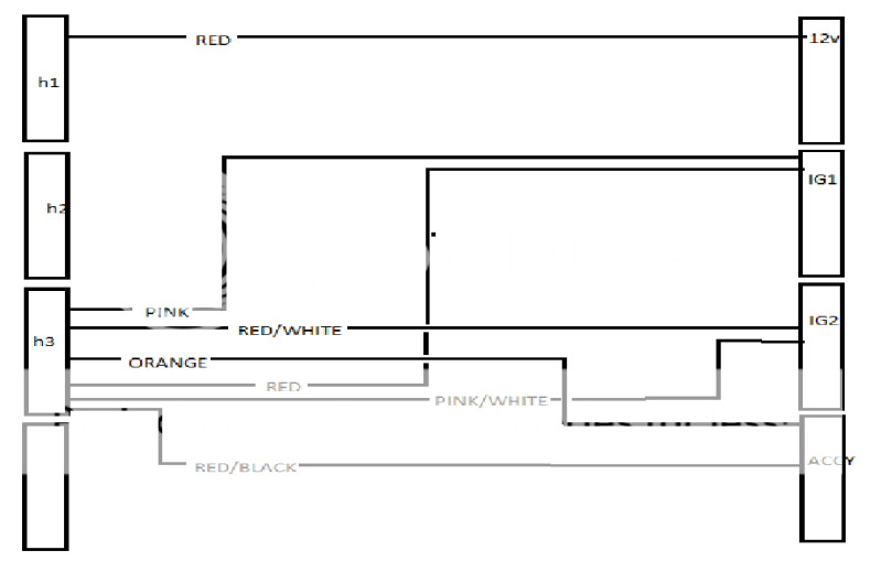
So this is what I have so far. Keep in mind these are just power wires according to what I'm reading from the install manual. Yes, I will add fuses. What do you all think?
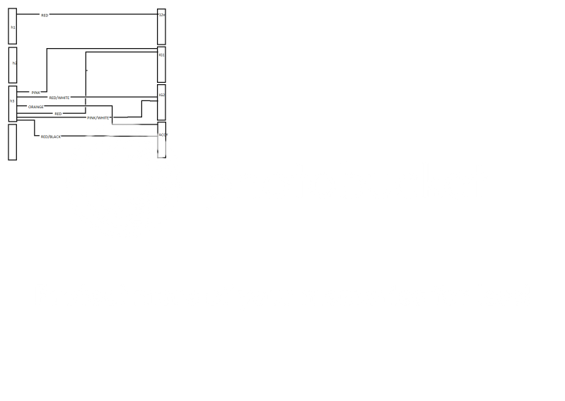
Posted By: zerovandez
Date Posted: May 31, 2011 at 1:04 PM
Sorry, here's a bigger picture
Posted By: kreg357
Date Posted: May 31, 2011 at 1:18 PM
No. The H3 wires, Red, RED / White and RED / Black all go to +12 constant just like the H1/2 Red wire.
-------------
Soldering is fun!
Posted By: zerovandez
Date Posted: May 31, 2011 at 1:54 PM
Thanks. I'll modify it to match your suggestion. I wonder why the manual specifiy these connections to the said terminals. Or I just may be interpereting them incorrectly. Otherwise, all other connections look fine?
Posted By: kreg357
Date Posted: May 31, 2011 at 3:08 PM
DEI Viper manuals are written for their trained, authorized techs and are ( IMHO ) deliberately vague. Most wiring guides are suggesting one IGN and two ACC's. Did you verify all the ignition wires with a DMM?
-------------
Soldering is fun!
Posted By: howie ll
Date Posted: May 31, 2011 at 3:54 PM
Everything kreg said is correct and I don't think you're listening that well especially with ref: to the red, RED / white and RED / black.
I've already said at least twice, that this vehicle has one starter, one ignition and two accessories. it doesn't matter which acc you nominate as the primary, just treat the other (wire it)as per second ignition.
-------------
Amateurs assume, don't test and have problems; pros test first. I am not a free install service.
Read the installation manual, do a search here or online for your vehicle wiring before posting.
Posted By: zerovandez
Date Posted: May 31, 2011 at 7:29 PM
Sorry guys. I can't really test anything right now since the car is in pieces. I'll charge the battery and test with a DMM ASAP. Thanks for all of your replies. Together, we'll get my car secure!
Posted By: zerovandez
Date Posted: June 01, 2011 at 7:57 PM
So here are my test results. They key cylinder actually has these outputs labeled!
Battery -white - no key, 12 volts
ACC - WHITE/ black - 12 volts when key turned to position 1, drops to 0v when starting
IG1 - BLACK / YELLOW - 12 volts when key turned to position 2, Drops to 8v when starting
IG2A - Yellow - 12 volts when key turned to position 2, drops to 0 when starting
Start - BLACK/ white - only 12 volts when starting
So I can see why you all say ACC and IG2A are the same. Maybe the "A" in IG2A is there to suggest it's an accessory also.
Posted By: zerovandez
Date Posted: June 01, 2011 at 8:10 PM
Also, on the key solenoid, they're bare solder pads. Looks like I can just solder a tinned 10 gauge wire to what I need instead of splicing the wires. Are there any objections in doing it this way?
Posted By: howie ll
Date Posted: June 02, 2011 at 2:21 AM
Yes, no problem with soldering directly. And yes the yellow wire can be ignition 2 OR ACC 2 it makes no difference as long as you wire it up correctly.
-------------
Amateurs assume, don't test and have problems; pros test first. I am not a free install service.
Read the installation manual, do a search here or online for your vehicle wiring before posting.
Posted By: zerovandez
Date Posted: June 02, 2011 at 11:36 AM
So in all of this madness, I wired in a fuel kill switch with the idea of it being triggered by the orange ground when armed output on the H1 harness. But...I'm going to have a problem with remote start if I keep it this way won't I? I'd have to disarm the alarm to remote start but that's pretty dumb. Is there a way around this with keeping a fuel kill relay?
Posted By: howie ll
Date Posted: June 02, 2011 at 12:22 PM
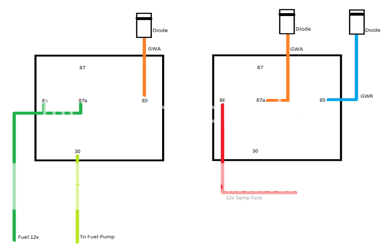
Replace your switch with this:
Use a relay thus:
85 = alarm GWA
86 and 87a feed to fuel pump from ignition
30 cut side to fuel pump
now do this with a second relay:
ground whilst armed to 87a
status output (GWR) from alarm to 85
constant live with a 3amp fuse to 86
other side of cut GWA wire to 85 on the original relay.
This will give you a fuel cut whenever the alarm is on except when you do a remote start.
-------------
Amateurs assume, don't test and have problems; pros test first. I am not a free install service.
Read the installation manual, do a search here or online for your vehicle wiring before posting.
Posted By: howie ll
Date Posted: June 02, 2011 at 12:30 PM
Sorry, above post should have mentioned:
1N4004 diode in-line on both GWA and GWR wires just before the first relay, cathodes (bands) towards the alarm.
-------------
Amateurs assume, don't test and have problems; pros test first. I am not a free install service.
Read the installation manual, do a search here or online for your vehicle wiring before posting.
Posted By: zerovandez
Date Posted: June 02, 2011 at 3:08 PM
So this is my understanding of what you just said...but I'm missing something...
Posted By: howie ll
Date Posted: June 02, 2011 at 3:31 PM
Absolutely right except I've made an error 
On the left relay 86 should be connected to 86 on the right relay as a constant, not from the pump feed.
on the right relay, 30 goes to 85 on the left, 87 in both relays not used. ------------- Amateurs assume, don't test and have problems; pros test first. I am not a free install service.
Read the installation manual, do a search here or online for your vehicle wiring before posting.
Posted By: howie ll
Date Posted: June 02, 2011 at 3:39 PM
This;- relays.png------------- Amateurs assume, don't test and have problems; pros test first. I am not a free install service.
Read the installation manual, do a search here or online for your vehicle wiring before posting.
Posted By: howie ll
Date Posted: June 02, 2011 at 3:44 PM
Sorry, still didn't get it right, I'm lousy at graphics 277_relays.png------------- Amateurs assume, don't test and have problems; pros test first. I am not a free install service.
Read the installation manual, do a search here or online for your vehicle wiring before posting.
Posted By: zerovandez
Date Posted: June 02, 2011 at 8:56 PM
Haha! That's awesome. Thanks for taking the time to do that before I was able to revise it myself. As for the GWR output, all components using this will need to be diode isolated right? Specifically I'm referring to using for the clutch switch ground which is a direct connect without a relay right?
Posted By: howie ll
Date Posted: June 03, 2011 at 12:25 AM
Yes.
-------------
Amateurs assume, don't test and have problems; pros test first. I am not a free install service.
Read the installation manual, do a search here or online for your vehicle wiring before posting.
Posted By: zerovandez
Date Posted: June 14, 2011 at 2:11 PM
It's been a while. So I got around to more testing and probing and I found which wire needs to see ground when pressing the clutch. I played around with my DMM and set it to OHM's setting and was able to figure it out. So yay for me! Hopefully this weekend, I'll have everything mounted and mocked up to my liking. Just waiting on the DEI 530T.
Posted By: howie ll
Date Posted: June 14, 2011 at 3:40 PM
Some practical advice; mount the 530 in the car and run out to each door and pick up the two wires going to each motor one of which will read 12v+ on up whilst the other stays at ground and vice versa. Ignore the switches, also you have type 1 or type A windows.
I know it's a PITA to get into the doors but worth it, you will have one-touch up and down from all your switches.
-------------
Amateurs assume, don't test and have problems; pros test first. I am not a free install service.
Read the installation manual, do a search here or online for your vehicle wiring before posting.
Posted By: zerovandez
Date Posted: June 14, 2011 at 5:44 PM
Awesome. Thanks for the insight. The driver side door is not all that hard to get wires through. It's the passenger side that is a complete pain, litterally. The space is so tight in there as I recall running speaker wires from an amp install.
Posted By: 87rewire
Date Posted: June 14, 2011 at 6:10 PM
Just reading through the thread. What is the purpose of the diode on the gwa wire? Is it to prevent unintentional grounding to the gwa wire?
Posted By: howie ll
Date Posted: June 15, 2011 at 12:32 AM
Yes. When relay coils have the power removed, there's often a spike and this can travel back up the lead to destroy the alarm circuitry.
Any low current device i.e. 100+ milliamps. Which is just about every make of alarm. Some people here think it's not needed, the alarm makers should put diodes on the board but I won't take the chance. I always put a diode either in line or across the coil with the band facing the + side (86). Look at the relay diagrams on this site.
-------------
Amateurs assume, don't test and have problems; pros test first. I am not a free install service.
Read the installation manual, do a search here or online for your vehicle wiring before posting.
Posted By: howie ll
Date Posted: June 15, 2011 at 12:41 AM
This is the alternative. B2D_relay_starter_cut.bmp------------- Amateurs assume, don't test and have problems; pros test first. I am not a free install service.
Read the installation manual, do a search here or online for your vehicle wiring before posting.
Posted By: zerovandez
Date Posted: June 17, 2011 at 1:13 PM
So while I'm at it, I was wondering about the the AUX functions on these alarm systems. Would there be a way for it to turn on my Air Condtioner? It seems a bit complicated because of the blower motor which is turned on at variable speeds with a knob on the center console switch. Or I can leave the blower "on" at any speed and just have the AUX switch on the A/C? Just wondering...
Posted By: zerovandez
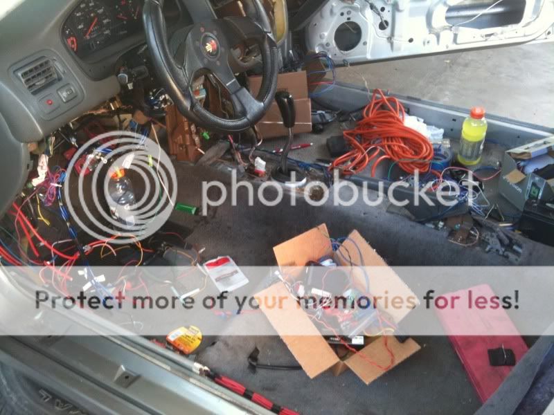
Date Posted: June 22, 2011 at 10:38 AM
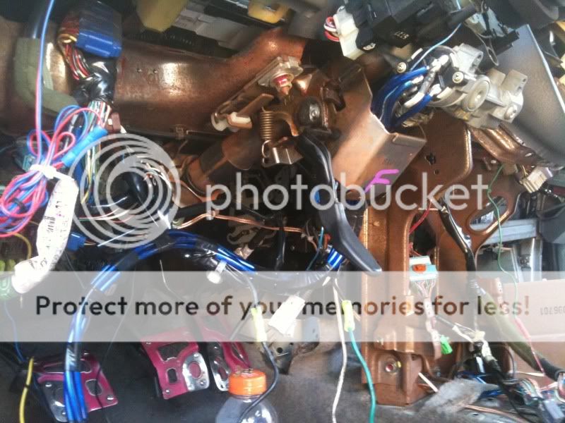
So I guess I'll turn this into my progress thread. Here is a picture of the car and it's wiring progress.


Posted By: howie ll
Date Posted: June 22, 2011 at 11:47 AM
Ref; the A/C in theory leaving it on overnight and powering up ALL the ignition loom wires should do it. Otherwise you will have to power up the output from the first position onwards on the blower.
Your Momo wheel is on the wrong bloody side.
-------------
Amateurs assume, don't test and have problems; pros test first. I am not a free install service.
Read the installation manual, do a search here or online for your vehicle wiring before posting.
Posted By: zerovandez
Date Posted: June 22, 2011 at 12:36 PM
Haha! only in America
So If I wanted to use AUX 2 to control a relay that turns on the AC, would the relay be like:
85 - AUX 2 from alarm harness
86 - +12v
87 - ground
30 - AC turn on wire
Posted By: howie ll
Date Posted: June 22, 2011 at 3:51 PM
No use this configuration, but see what happens when you turn your AC on, turn off engine then turn it on again, if the AC comes on, just leave it on overnight. The wiring to your relay is completely wrong. B58_1_relay_template.bmp
Use the same set-up for a defogger control. ------------- Amateurs assume, don't test and have problems; pros test first. I am not a free install service.
Read the installation manual, do a search here or online for your vehicle wiring before posting.
Posted By: zerovandez
Date Posted: June 23, 2011 at 11:47 AM
You just proved to me that I know nothing about relays. Haha! I think i'll just leave the AC on during a hot day. So I think I have it all set. Alarm, 530T, a few conveniece features. Going to start mounting everything up this weekend. I'll post more pictures of my progress. So many wires it looks like spaghetti!
Posted By: zerovandez
Date Posted: June 24, 2011 at 8:44 AM
Mounting of the alarm unit, and the 530T. Still have to mount the backup battery and relays. Most wire extensions are completed.
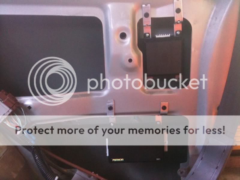
Posted By: howie ll
Date Posted: June 25, 2011 at 10:49 AM
What are we looking at? Driver or passenger kick panel?
-------------
Amateurs assume, don't test and have problems; pros test first. I am not a free install service.
Read the installation manual, do a search here or online for your vehicle wiring before posting.
Posted By: howie ll
Date Posted: June 25, 2011 at 10:52 AM
Sorry, just realised, it's the left hand rear 3/4 panel, where the back door would be. Good place if your cables are long enough though I'd have placed the R/S behind the dash, that is less of a length on the high powered stuff for the R/S.
Usually my favourite place for burying amps!
-------------
Amateurs assume, don't test and have problems; pros test first. I am not a free install service.
Read the installation manual, do a search here or online for your vehicle wiring before posting.
Posted By: zerovandez
Date Posted: June 27, 2011 at 8:46 AM
Yes, that's the driver side rear 3/4 panel (left). I've extended all of the R/S wires with true 10 gauge wires with solder and tested all connections for voltage drops. All seem to be working well. Next, I will need to wire in the 530T module and figure out what I want to do with the siren and/or horn.
Posted By: zerovandez
Date Posted: August 15, 2011 at 8:43 AM
It's been a while! I took a break for a long moment. Thus far, I've cleaned up the wiring, and started running them to where they need to terminate. I've mounted the alarm brain and the 520T.
I've got a problem with wiring the 520T on the passenger side. The wiring on this site states the motor up/down wires are BLUE / YELLOW and BLUE/ORANGE. On my car, these wires are present on the plug that connects to the switch, again, on the passenger side. But the 2 wires that run to the MOTOR are BLUE/WHITE and BLUE/RED then it connects to the motor plug. The wires on the motor are a SOLID RED and a SOLID YELLOW only. What to do?
Posted By: t&t tech
Date Posted: August 15, 2011 at 5:48 PM
You interrupt the motor wires, once you've tested and verified that they are indeed motor wires go right ahead, wiring diagrams are references.
-------------
COMMIT YOUR WAY TO JEHOVAH AND HE WILL ACT IN YOUR BEHALF.
PSALMS 37:5
Posted By: zerovandez
Date Posted: August 15, 2011 at 7:52 PM
Well, Just more history on this car; This model civic, 1997 Civic DX Hatchback, never came with power windows. I installed the power windows with OEM parts. I'm thinking that the passenger sides door harness is from an Acura Integra. The wires match up with that from the Integra...
Posted By: t&t tech
Date Posted: August 16, 2011 at 6:40 AM
OK.
-------------
COMMIT YOUR WAY TO JEHOVAH AND HE WILL ACT IN YOUR BEHALF.
PSALMS 37:5
Posted By: zerovandez
Date Posted: August 16, 2011 at 8:16 AM
Just for my own information, how do you test the wires? The owners manual is really vague on how to do this. I guess I'm not sure what and how to check?
Posted By: howie ll
Date Posted: August 16, 2011 at 9:20 AM
As posted before, use a DMM. Both motor wires should be negative at rest. On pressing switch up, one will will go to 12VPOS, and the other stay at NEG or ground, press switch for down then the wire that was at ground should go to 12VPOS and the other to ground. This is all explained in the manual.
2 points you are referring to a "520t". I assume you really mean a 530.
Second I'm surprised at the different colours, Honda have kept to the same colours since at least the mid 90s.
-------------
Amateurs assume, don't test and have problems; pros test first. I am not a free install service.
Read the installation manual, do a search here or online for your vehicle wiring before posting.
Posted By: zerovandez
Date Posted: August 16, 2011 at 12:23 PM
Thanks Howie! Yes, I meant 530T. Still fiddling with the mounting the battery of the 520T. Again, I have a honda, modified to fit factory power windows, and I'm assuming I'm using Acura Integra door harness so the colors would be different as they are described on this website.
Posted By: howie ll
Date Posted: August 16, 2011 at 12:28 PM
Very unlikely, the Japanese are the most logical nation when it comes to wiring colours and continuity of those colours, also remember, everywhere else bar the US there's no Acura, it's all Honda.
Just test.
-------------
Amateurs assume, don't test and have problems; pros test first. I am not a free install service.
Read the installation manual, do a search here or online for your vehicle wiring before posting.
Posted By: zerovandez
Date Posted: August 17, 2011 at 9:00 AM
Thanks. The battery is dead again and I will def test once it's charged. And while I'm finishing things up and the car still apart. Do you know of a relay diagram that would allow me to setup "priority unlock" where the driver side unlocks first? I couldn't find any with my searches.
Posted By: howie ll
Date Posted: August 17, 2011 at 10:44 AM
Try this, notice I'm using the motor wires in each case.
Z53_priority_unlock.bmp------------- Amateurs assume, don't test and have problems; pros test first. I am not a free install service.
Read the installation manual, do a search here or online for your vehicle wiring before posting.
Posted By: zerovandez
Date Posted: August 18, 2011 at 8:19 AM
Thanks. So after looking at the relay diagram here, and another relay diagram for the 2nd unlock else where, I came up with this;
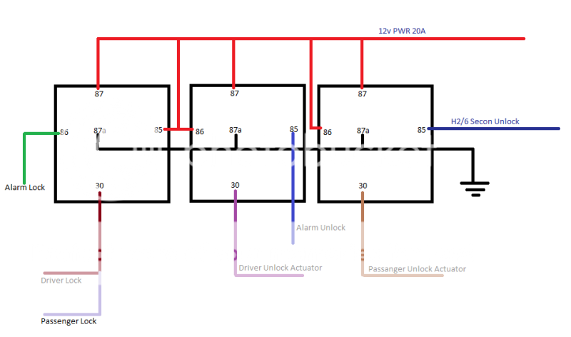
Posted By: howie ll
Date Posted: August 18, 2011 at 9:08 AM
Which will blow all your fuses!
In my CORRECT diagram, 87a is the control side and 30 is the door side, you cut those motor wires and join to 87a and 30. UNLESS... you are going to completely control it from the alarm, and disregard the factory control unit then you're correct.
-------------
Amateurs assume, don't test and have problems; pros test first. I am not a free install service.
Read the installation manual, do a search here or online for your vehicle wiring before posting.
Posted By: zerovandez
Date Posted: August 18, 2011 at 9:31 AM
LOL! My car doesn't have factory alarm and/or keyless entry. I'm using aftermarket 2 wire actuators.
Posted By: howie ll
Date Posted: August 18, 2011 at 9:40 AM
Then use YOUR diagram, it's fine.
-------------
Amateurs assume, don't test and have problems; pros test first. I am not a free install service.
Read the installation manual, do a search here or online for your vehicle wiring before posting.
Posted By: zerovandez
Date Posted: August 19, 2011 at 10:56 AM
Finally, I feel that I've got something right haha! So after reading a few others installation posts about this kind of alarm, I've come to find I'm learning about H3/3 Accessory Output (+). I was originally thinking this wire is supposed to be connected to the Accy wire on the Ignition switch but after some reading and common sense, I'm finding out that this is probably incorrect. The install guide says to connect it to the Accy wire that powers the climate control unit but the alarm, in my case, will not have anything to do with the climate control other than the defrost output. So should I even connet this to anything? I really don't see a need for it.
Posted By: howie ll
Date Posted: August 19, 2011 at 10:58 AM
It's optional.
-------------
Amateurs assume, don't test and have problems; pros test first. I am not a free install service.
Read the installation manual, do a search here or online for your vehicle wiring before posting.
Posted By: zerovandez
Date Posted: August 23, 2011 at 9:12 PM
So after careful observation and research, I find that my Python 991 is a newer version with a 16 pin harness as opposed to what was offered prior, which had a few AUX harnesses. My main concern is that my "newer" model does NOT have a 2nd unlock output! Ive been following the manual online but didn't notice that until I went to connect everything up. Is there anything I can do which would allow for a 2nd unlock output on my newer python 991? And no, I wouldn't want to use any AUX commands for a 2nd unlock.
Posted By: zerovandez
Date Posted: August 23, 2011 at 10:25 PM
So I think I found my answer after more reading. I downloaded the manual for the Viper 5701 w/new H2 connector and it's just like my new version python 991. The features menu lists any AUX output can be programed as 2nd unlock. Here is the description:
2nd unlock: the wire will operate as 2nd unlock and will not activate for remote control commands.
I'm not understanding what "will not activate for remote control commands" mean. Can anyone verify that I'm on the right path? Thanks!
Posted By: howie ll
Date Posted: August 23, 2011 at 11:55 PM
Simply what it says, 2nd unlock ONLY, not an aux wire.
You can double it up with a latching relay, such that when the vehicle is armed it becomes an aux and when disarmed the 2nd lock wire. Are you using ALL of your aux outputs anyway?
-------------
Amateurs assume, don't test and have problems; pros test first. I am not a free install service.
Read the installation manual, do a search here or online for your vehicle wiring before posting.
Posted By: zerovandez
Date Posted: August 24, 2011 at 7:33 AM
No I'm just using the trunk, and AUX 1 (For the 530T). Thanks again, wiriing is almost done!
On a side note, would you happen to know if the dome light turns on when the rear hatch is opened? I can't remember. Otherwise, I'll wait until I get a charged battery to test.
Posted By: zerovandez
Date Posted: August 28, 2011 at 11:47 AM
So I finally got everything connected and power is good! The 530T works very well. I do have a few issues
1) Light flash output not working. I tested the white wire from the python 991 and it's outputting 12 volts when arm/disarm.
2) I can't seem to access the programming of the alarm. I've tried to start the engine, turn it off, then press and hold the Control Center button but I never hear any siren chirps that alerts me of which menu I'm in. Instead, I see "valet" on my remote.
3) My remote start will not work. My remote beeps 7 times and it seems to be a MTS error or tach learning error. I've tried to setup the tach a few times and the light on the Control Center suggests that everything is working as if it's learning the tach. Not sure...
Posted By: zerovandez
Date Posted: August 28, 2011 at 6:28 PM
I went through the remote start procedure
1) start car
2) press and hold brake pedal
3) lift ebrake (BLACK/ white wire from 18 pin harness)
4) release brake pedal
5) press remote start on remote
6) remove keys
7) arm alarm
But the car never remote starts again. Not sure where to look.
I've checked the brake shutdown input, the ebrake neutral input, and the clutch switch. I'm not sure where else to look. The problem seems to be with this initial remote start step, it's just not getting passed it.
Got the lights flashing. It was just a poor connection. So I tried the remote start procedure again and now theres 5 flashing lights which indicates an active brake wire during remote startup. The brain does something strange during the manual tranny process; it turns on all brake/flashing flights before you are instructed to get out of the car. Is this normal? Such is why the brown wire is seeing 12v and flashing 5 times...
Posted By: zerovandez
Date Posted: August 29, 2011 at 5:17 PM
So i figured out more than half of my problems with programming. A poor connection was made from the green trigger wire to the door wire. So I'm able to do the programming I want. The priority lock works, the horn honk works, and a few other features work really well. The only thing still wrong is the remote start. I cannot get it to initialize. I get passed the setup steps, then I press the lock button and it fails to remote start.
Posted By: zerovandez
Date Posted: August 30, 2011 at 8:08 AM
I'm getting help on a honda specific forum and someone mentioned I need to wire a relay to the 520T's instant trigger output to isolate it during startup as It causes a voltage drop when starting that triggers the alarm and it stops the remote start process. Which relay diagram should I be looking at?
Posted By: KPierson
Date Posted: August 30, 2011 at 9:57 AM
How are you making connections? Two poor connections causing problems? I would reconsider whatever method you are using.
-------------
Kevin Pierson
Posted By: KPierson
Date Posted: August 30, 2011 at 10:00 AM
If you think that is the issue just disconnect the output of the 520T and see if the problem goes away. I am thinking it won't, but I can't say that I've ever tried that situation. I am almost positive though that an alarm situation will not shut the remote start down - only a brake input, a timer time out, a remote command, or a tach over rev condition will cause the remote start to shut down.
-------------
Kevin Pierson
Posted By: howie ll
Date Posted: August 30, 2011 at 10:21 AM
Either listen to KP because your connections might not be good enough at the start of the R/S cycle OR use a 528t set for 10 seconds as the diagram use a status wire (GWR) and diode as shown also follow the colours exactly, this will isolate the 520t trigger for 10 seconds.
As KP was hinting, with decent connections your problem shouldn't arise.
Just as a thinking point, most of the problems on this site are from people simply not reading the instructions thoroughly, the second from poor wiring.
As a diagnostic precaution, disconnect the blue wire from the 520t just to see if that's actually the problem.:- 520t_interrupt.bmp
Also please remember my caution about 7 pages ago about situating your control units so far from the battery.
Is this the longest ever post? ------------- Amateurs assume, don't test and have problems; pros test first. I am not a free install service.
Read the installation manual, do a search here or online for your vehicle wiring before posting.
Posted By: howie ll
Date Posted: August 30, 2011 at 10:23 AM
Kevin, we crossed paths/posts but effectively we're saying the same thing.
-------------
Amateurs assume, don't test and have problems; pros test first. I am not a free install service.
Read the installation manual, do a search here or online for your vehicle wiring before posting.
Posted By: howie ll
Date Posted: August 30, 2011 at 10:25 AM
Read Kevin's last post ref: stopping the process. I still don't think it's the 520t.
-------------
Amateurs assume, don't test and have problems; pros test first. I am not a free install service.
Read the installation manual, do a search here or online for your vehicle wiring before posting.
Posted By: zerovandez
Date Posted: August 30, 2011 at 10:43 AM
I'll disconnect it from the trigger as soon as I get home to test. I was using those wire taps before to tap into the door/trunk trigger, tach, and brake. I've removed them and used solder instead. I've tested all connections after soldering and all triggers are working as they should.
Over rev? Maybe this is because the car is not warm yet? Cold idle RPM starts at around 1.5k, after it warms up it will idle to around 800-1k RPM. Should I wait until it's warm?
A reputable source has advised me of the 520T problem. This source is well known in the Honda forums and has helped me just as you all have with other things. I've researched this problem online, and although not common, it does show as being a problem for some installations. Again, information is really scarce regarding this.
Howie, I'm understanding your concern about the longer heavy gauge power wires. What should I test for?
Posted By: howie ll
Date Posted: August 30, 2011 at 10:57 AM
Check the voltage at the heavy gauge fused wires and the alarm red if present, set your pos probe to the plugs at the alarm etc. and your neg. to the alarm's black wire.
If that reads below 12.3 you've got problems.
-------------
Amateurs assume, don't test and have problems; pros test first. I am not a free install service.
Read the installation manual, do a search here or online for your vehicle wiring before posting.
Posted By: howie ll
Date Posted: August 30, 2011 at 10:59 AM
One phrase in connection with joints. SOLDER SOLDER SOLDER. And read KP's posts in the archives on how to solder.
-------------
Amateurs assume, don't test and have problems; pros test first. I am not a free install service.
Read the installation manual, do a search here or online for your vehicle wiring before posting.
Posted By: zerovandez
Date Posted: August 30, 2011 at 11:31 AM
Yeah, I've soldered many times before with R/C cars and other hobbies. I'ved checked the voltages to the connections and they do show voltage above 12.3v when the car is off (no alternator running, engine off).
I agree, this is the longest thread ever. I just want to get things done right. I hope this thread helps someone in the future.
Posted By: howie ll
Date Posted: August 30, 2011 at 11:35 AM
Good so that eliminates 1 possible problem.
-------------
Amateurs assume, don't test and have problems; pros test first. I am not a free install service.
Read the installation manual, do a search here or online for your vehicle wiring before posting.
Posted By: zerovandez
Date Posted: August 30, 2011 at 11:52 AM
For more info, the car doesn't even attempt to crank in the final process of the MTS initiation procedure (after stepping out of the vehicle, and pressing the lock button on the remote). Not sure if this would show any problems.
Posted By: KPierson
Date Posted: August 30, 2011 at 1:51 PM
What I would advise, and this is for testing only, is to put it in auto transmission mode. You need to determine if the the problem is with the remote start or the manual transmission interface.
How did you bypass the clutch switch?
As Howie said, solder everything. T-taps and scotchlocks are just asking for problems.
Howie, I have a thread in the archive about soldering??????
-------------
Kevin Pierson
Posted By: howie ll
Date Posted: August 30, 2011 at 2:17 PM
Kevin, General Discussion, how to solder etc. the last post with a great picture.
That thread and the next on joining wires should be required reading along with any of Chris Luongo's how to posts and ahem mine "All rookies" etc. which is in the Security Hot Topics Section
-------------
Amateurs assume, don't test and have problems; pros test first. I am not a free install service.
Read the installation manual, do a search here or online for your vehicle wiring before posting.
Posted By: zerovandez
Date Posted: August 30, 2011 at 2:24 PM
Thanks KP, I'll do that as well after I test the instant trigger.
The clutch switch is activated by ground. There's 2 wires, just jump them together. Yeah I've removed the Ttaps and soldered the connections and tested them very thorougly. They all work as they should. Not sure how to test the tach wire besides for continuity back to the alarm brain with a DMM.
Posted By: howie ll
Date Posted: August 30, 2011 at 4:38 PM
Re tach wire...start the engine and simply test for tach at the alarm's brain...no continuity required because if you get the right reading, continuity is a given.
Don't worry, give it another 20 years or so and we'll teach you how to do diagnostics.
-------------
Amateurs assume, don't test and have problems; pros test first. I am not a free install service.
Read the installation manual, do a search here or online for your vehicle wiring before posting.
Posted By: howie ll
Date Posted: August 30, 2011 at 4:42 PM
Actually sorry for sounding so patronising, it's just that with things like diagnostic problem solving you need to
A) Know what something is supposed to do.
B) Know exactly how to test.
C) Have some years of hands on test and repair.
-------------
Amateurs assume, don't test and have problems; pros test first. I am not a free install service.
Read the installation manual, do a search here or online for your vehicle wiring before posting.
Posted By: zerovandez
Date Posted: August 30, 2011 at 6:29 PM
I respect your experience, no need to apologize.
Here are the results:
1) Removed the blue instant trigger, left in MTS mode, remote start failed.
2) Put the alarm in Auto mode, it worked! Reconnected trigger, remote start still worked!
3) Put back to MTS, relearn tach, remote start fail! rewired the tach wire straight to the distributor, remote start still fails! not sure where else to look. All of the required connections are making good connection.
I did notice something different; The "stick shift/remote enabled" icon appeared. The manual indicates when this is on, remote start can be used. But at the end of the process, the remote outputs "remote start off." It did just error out this time around...
Posted By: KPierson
Date Posted: August 30, 2011 at 7:23 PM
If it works in "auto" mode but doesn't work in "manual" mode why would you assume tach? The tach had to be connected properly, otherwise it wouldn't have started in "auto" mode!
If it simply won't start in manual mode you need to look at the things that are specific to manual mode. Parking brake, door trigger, etc. Make sure you are following the instructions precisely on arming the manual mode. If you skip a step or do them out of order it won't work.
-------------
Kevin Pierson
Posted By: zerovandez
Date Posted: August 30, 2011 at 7:45 PM
Oh...duh... I'm going to quadruple check the connections now. Mind you that all other electronics are taken apart as well. There aren't any heater/ac/def controls and no radio. Not sure what difference that will make. Thanks for all of your input.
Posted By: zerovandez
Date Posted: August 30, 2011 at 9:31 PM
I'm feeling kind of stupid and here's why....
My "new version" Python 991 has it's own owners manual, that I just found in the box. I was following online manuals for the "older" Python 991. The MTS remote procedure is totally different from each other (new to old).
Here's how it worked...I did the MTS procedure, again the "new" way, and I was able to remote start it successfully. I disarmed the car, put the key to ON, press the brake, relays go off/on, then my remote says REMOTE START OFF. I turn off the car step outside, then try to remote start again. It fails.
Am I supposed to do the MTS procedure every time I step out of the car if I want to remote start it the next time I decide to drive it? I don't have a problem with it, I just want to understand that I've got this to work the way it should.
EDIT: But here's the MOST annoying part. After performing the MTS procedure, they (DEI) instruct you to get out of your vehicle, and CLOSE the door, which is fine and dandy. But after you've successfully completed this procedure, All of the relays get activated....including the DOME LIGHT SUPERVISION relay which stays ON after you get out of the car. So you have to wait until that relay shuts off BEFORE you press the lock button to fully enable MTS mode, otherwise, MTS mode will FAIL. And there's probably not a way around this one....I'm almost inclined to leave it on Auto mode and change it whenever I Valet or if I'm not the driving it. But like I said, I would like to know if this procedure has to completed All of the time. Or is there a memory issue with my unit?
Posted By: howie ll
Date Posted: August 31, 2011 at 2:17 AM
Loose the dome light supervision. Or something is wrong with your wiring, I've never known domelight supervision to stay on during remote start manual prep, in other words, once you exit the vehicle with engine running, shut the door and activate the alarm, doors lock, engine shuts down, walk away, then provided nothing triggers the alarm you should be able to turn on the remote start at will.
I'd be looking at the door/hood triggers.
-------------
Amateurs assume, don't test and have problems; pros test first. I am not a free install service.
Read the installation manual, do a search here or online for your vehicle wiring before posting.
Posted By: KPierson
Date Posted: August 31, 2011 at 5:24 AM
The purpose of the manual transmission mode is to prove to the brain that the car isn't in gear so that the car can be started safely. Therefore, you have to do it every time.
I'm with Howie, something doesn't seem right with the dome light.
-------------
Kevin Pierson
Posted By: zerovandez
Date Posted: August 31, 2011 at 7:40 AM
Okay, So I'm right about having to do the MTS procedure everytime I want to remote start the car the next I drive it.
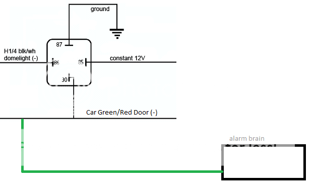
The domelight relay is connected to the door trigger(-) on the car. The alarm door trigger input (-) is also connected to the cars door trigger wire. Maybe this is a problem?
During MTS mode, the car flashes 5 times, just like the manual states. But after that 5th blink, and half a second later, the dome light triggers on. I'm thinking I may need to install diodes on the domelight and door trigger?
Here is a visual of how my expert wiring looks like. The green is the door trigger from the alarm.
Posted By: howie ll
Date Posted: August 31, 2011 at 7:51 AM
Doesn't dome light supervision go through a relay? In that case diodes are unnecessary.
The fact that the dome light comes on during remote start points to either bad wiring or a faulty switch, the dome light supervision should ONLY work on de-activating the alarm, nothing to do with the remote start sequence.
This is G4/5 Clifford but it's effectively the same:-
Engine running parking brake on.
Press the button that controls remote start manual supervision.
Remove key and exit the vehicle, engine should still be running.
Shut the door(s), turn on alarm, doors will lock, windows should close if a window closer present, engine will shut down after 1-4 seconds.
-------------
Amateurs assume, don't test and have problems; pros test first. I am not a free install service.
Read the installation manual, do a search here or online for your vehicle wiring before posting.
Posted By: zerovandez
Date Posted: August 31, 2011 at 8:35 AM
Yes, through a relay. Refer to my picture above. Well maybe I should try connecting it to the actual dome light wire instead of something that triggers it.
Posted By: KPierson
Date Posted: August 31, 2011 at 8:48 AM
The issue is that if the alarm sees that a door is open, it cancels the manual transmission mode, because it is possible that you put the car in gear when you were in the car. So, what is happening, is your domelight relay is making the alarm think the door is open.
-------------
Kevin Pierson
Posted By: howie ll
Date Posted: August 31, 2011 at 8:48 AM
Sorry, somehow missed the diagram before.
Except you're still missing the point KP and I are trying to make, about the dome light. It shouldn't come on during remote start with the doors locked.
-------------
Amateurs assume, don't test and have problems; pros test first. I am not a free install service.
Read the installation manual, do a search here or online for your vehicle wiring before posting.
Posted By: zerovandez
Date Posted: August 31, 2011 at 9:23 AM
You guys are right, the dome light should turn off when arming the alarm to complete the MTS mode. It just hit me that my door panels are not installed. Maybe the pin that terminates the connection on the door is not being pressed in all of the way (because the missing door panels). Next time, I'll manually press the switch down myself and arm the alarm to test. I THOUGHT I did that yesterday and was sitting there wondering why the domelight was still on, then I heard the click on the relay which triggered the domelight to turn off. I could be wrong. We're almost there fellas! Almost done!
Posted By: zerovandez
Date Posted: August 31, 2011 at 4:47 PM
1st Test:
1) MTS procedure everything connected
2) Dome light turns off with Arming alarm
3) Remote start fail
2nd Test:
1) MTS Procedure
2) Wait until dome light turns off
3) Remote start success
3rd Test
1) Disconnect power to dome light relay
2) MTS procedure
3) Remote start success
Clearly, the problem is that the dome light relay, in MTS procedure while still on, will cause the remote start to fail even if the arm command is sent turning the relay off. All other connections are correct (being that I'm able to remote start with the relay disconnected). Really strange.
Posted By: howie ll
Date Posted: August 31, 2011 at 5:09 PM
Rewire the relay thus:- dome.bmp
Make sure your ground is connected to 87 NOT 87a and you follow my (correct) pin configuration, also the diode as shown. ------------- Amateurs assume, don't test and have problems; pros test first. I am not a free install service.
Read the installation manual, do a search here or online for your vehicle wiring before posting.
Posted By: zerovandez
Date Posted: August 31, 2011 at 5:35 PM
Thanks howie. What will adding the diode do? Will it take away the domelight capability when disarming regularly?
Posted By: zerovandez
Date Posted: August 31, 2011 at 5:59 PM
Well. It didn't work. Wired it just as per your diagram. Again, the funny thing is that during MTS procedure, the lights flash 5 times like the manual says, then it flashes once more and stays solid. That's when the domelight gets activated. Not sure what's causing this.
Posted By: howie ll
Date Posted: August 31, 2011 at 5:59 PM
It should block any feedback and remember what I said about 87a, also have you checked your door switches yet? If they are the sliding type they corrode easily.
-------------
Amateurs assume, don't test and have problems; pros test first. I am not a free install service.
Read the installation manual, do a search here or online for your vehicle wiring before posting.
Posted By: zerovandez
Date Posted: August 31, 2011 at 6:01 PM
Yeah, checked door switches, checked everything. For some reason, that BLACK/ white wire is getting activated during the MTS procedure.
Posted By: howie ll
Date Posted: August 31, 2011 at 6:05 PM
Faulty unit?
-------------
Amateurs assume, don't test and have problems; pros test first. I am not a free install service.
Read the installation manual, do a search here or online for your vehicle wiring before posting.
Posted By: zerovandez
Date Posted: August 31, 2011 at 6:09 PM
I have not a clue lol. Everything seems to work just right except for that one issue. Well I'm glad we narrowed it down to that being the only problem. I guess waiting for the dome light to switch off is not going to be so bad. It's not like I plan to use the remote start all of the time I want to drive the car.
I doubt that I can get my hands on another brain unit being that they are so expensive.
Posted By: KPierson
Date Posted: August 31, 2011 at 6:26 PM
Is this a 2 door or 4 door? You should be able to isolate the door pins with diodes and wire the dome light relay after the diodes. Wouldn't be too bad if it is only a 2 door, would be more cumbersome on a sedan.
Does the dome light output have any secondary uses? There may be different modes in the programming to get it to act differently. I would doubt it would be a faulty unit - faulty programming maybe!
-------------
Kevin Pierson
Posted By: zerovandez
Date Posted: August 31, 2011 at 7:23 PM
It's a 3 door hatchback. The main lead to the dome light is triggered by the passenger door. The driver door just taps into it but it completes the same circuit as the passenger. I don't think the actual light is the issue at this point. It's the alarm triggering the domelight output upon completing the MTS mode. I'm not sure what programing there is to complete for this output, i didn't see it on the menu.
Posted By: KPierson
Date Posted: August 31, 2011 at 8:35 PM
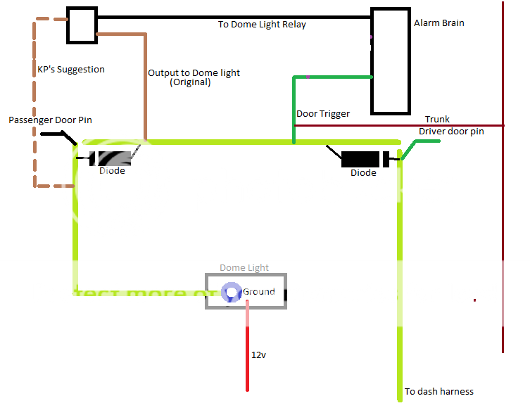
If you cut both door pin wires, and install diodes (bands facing towards door pins) and then run wires from each door pin to the alarm door pin input you can then hook the dome light output to the dome light side of the diodes and therefore your dome light output can come on (whether it is right or wrong that is a different question) and it won't trigger the door pin.
-------------
Kevin Pierson
Posted By: zerovandez
Date Posted: September 01, 2011 at 8:24 AM
The diagram below illustrates what I'm understanding from you. The brown dotted line from the relay to the passenger side before the diode is your suggested line. Yes, I have my trunk trigger tied in with instant trigger. While testing, I also removed the trunk trigger and left it connected, it didnt make a difference.
Posted By: howie ll
Date Posted: September 01, 2011 at 8:44 AM
No, the dome output should go to the door switch side. Look at this:-
3FF_dome.bmp------------- Amateurs assume, don't test and have problems; pros test first. I am not a free install service.
Read the installation manual, do a search here or online for your vehicle wiring before posting.
Posted By: KPierson
Date Posted: September 01, 2011 at 8:57 AM
Howie, that is close, but not quite. You need to reverse the "to alarm" connection and the "30" connection. The alarm needs to trigger directly off the door pins and the dome light activation needs to be isolated from those points by the diodes.
-------------
Kevin Pierson
Posted By: zerovandez
Date Posted: September 01, 2011 at 9:02 AM
So is my diagram correct? 2 diodes and relocate the wire coming from 30 off of the relay is what I'm understanding.
Posted By: howie ll
Date Posted: September 01, 2011 at 9:10 AM
Sorry Kevin, can't seem to get my head around, Happy Birthday by the way.
-------------
Amateurs assume, don't test and have problems; pros test first. I am not a free install service.
Read the installation manual, do a search here or online for your vehicle wiring before posting.
Posted By: KPierson
Date Posted: September 01, 2011 at 9:14 AM
This is how I would do it:
 ------------- Kevin Pierson
Posted By: howie ll
Date Posted: September 01, 2011 at 9:23 AM
Except the way you just showed only picks up one door switch!
-------------
Amateurs assume, don't test and have problems; pros test first. I am not a free install service.
Read the installation manual, do a search here or online for your vehicle wiring before posting.
Posted By: KPierson
Date Posted: September 01, 2011 at 9:32 AM
You are correct, you'll need to make sure you tap in to both feeds. It would probably be best to diode isolate the two separate feeds but I don't think it would be 100% necessary!
-------------
Kevin Pierson
Posted By: zerovandez
Date Posted: September 01, 2011 at 9:58 AM
Thanks guys, I'll try that. At this point, I'm a little sick of cutting and soldering lol. While on the subject, why is my alarm brain activating the output on remote start procedure? Is there a setting I missed somewhere? I've tried searching extensively for a scenario like mine but didn't find anything like it.
Posted By: KPierson
Date Posted: September 01, 2011 at 10:04 AM
My guess is that the system turns the dome light on when you remotely turn off the remote start. This setup probably works great in 100% of the auto tranny vehicles but was probably overlooked as a bug in your particular situation.
I know that not many people hook up the dome light output.
-------------
Kevin Pierson
Posted By: howie ll
Date Posted: September 01, 2011 at 10:06 AM
Have you actually tested H1/4 to see if it goes NEG (to ground) on remote start?
-------------
Amateurs assume, don't test and have problems; pros test first. I am not a free install service.
Read the installation manual, do a search here or online for your vehicle wiring before posting.
Posted By: zerovandez
Date Posted: September 01, 2011 at 12:00 PM
No I have not. But what else could be triggering it besides that ground lead? I definitely believe the command is coming from the brain but I'll test that too to make sure. Thanks guys for your efforts in helping me, it's much appreciated!
Now what would happen if I had my 87 and 85 on the relay mixed up? Would that be causing this?
Posted By: KarTuneMan
Date Posted: September 01, 2011 at 11:00 PM
What ever you put "to" 87, 30 will become, when the relay is activated. 85 and 86 work the relay...
Posted By: howie ll
Date Posted: September 03, 2011 at 12:03 AM
Forget the flipping dome supervision and get a Velleman kit for it or use this method:-
Use a 5 pin relay and a DEI 528t timer.
Relay don't use 87, 528t, don't use orange wire.
relay;
85 to ground.
86 to ignition (BLACK / YELLOW) source.
87a constant 12V+, fused at 5 amps.
30 feeds the 528t.
528t;
Red to relay 30.
Black and brown, ground.
Cut door trigger feed AFTER alarm connection,
BLACK/ white to door trigger side and yellow to dome light side.
This will give you dome supervision if you set the 528t for a minute every time you open a door but turn off the dome light as soon as you turn on the ignition, independent of the alarm, so, problem solved.
-------------
Amateurs assume, don't test and have problems; pros test first. I am not a free install service.
Read the installation manual, do a search here or online for your vehicle wiring before posting.
Posted By: t&t tech
Date Posted: September 05, 2011 at 6:36 PM
This is one of the longest threads I've seen in quite a while.
-------------
COMMIT YOUR WAY TO JEHOVAH AND HE WILL ACT IN YOUR BEHALF.
PSALMS 37:5
Posted By: howie ll
Date Posted: September 05, 2011 at 6:40 PM
I think it holds the all-time record  ------------- Amateurs assume, don't test and have problems; pros test first. I am not a free install service.
Read the installation manual, do a search here or online for your vehicle wiring before posting.
Posted By: zerovandez
Date Posted: September 05, 2011 at 7:25 PM
LOL! Hey but I'm learning and things are starting to come together! This is the only problematic issue left. Again, I'm sure someone will benefit from all of this information in the future as well. Should be sticky!
Just got back from a hike in the Grand Canyon. Yeah I needed a break from it all lol. I'll give that a shot, Howie being that I have not done anything else yet.
And again, for the record; the passenger side is the SAME wire that connects to the dome light. They aren't separate circuits. Not sure If I would need to use diodes for Howie's new instructions.
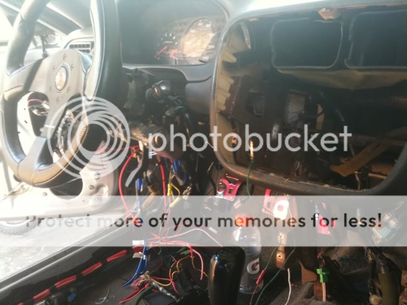
Here is a picture of my interior's wiring. I hope this helps you help me...
Posted By: zerovandez
Date Posted: September 06, 2011 at 2:04 PM
So after looking at this myself, would it be possible to diode isolate the passenger door trigger for the dome light and door triggers seperately? Basically installing 2 diodes on the passenger door trigger, run one diode to the door trigger/dome light, and run the other diode to the dome light relay. Would this work out?
Posted By: howie ll
Date Posted: September 06, 2011 at 3:26 PM
Try this, you made me think of an answer:- door_switch.bmp------------- Amateurs assume, don't test and have problems; pros test first. I am not a free install service.
Read the installation manual, do a search here or online for your vehicle wiring before posting.
Posted By: zerovandez
Date Posted: September 06, 2011 at 4:00 PM
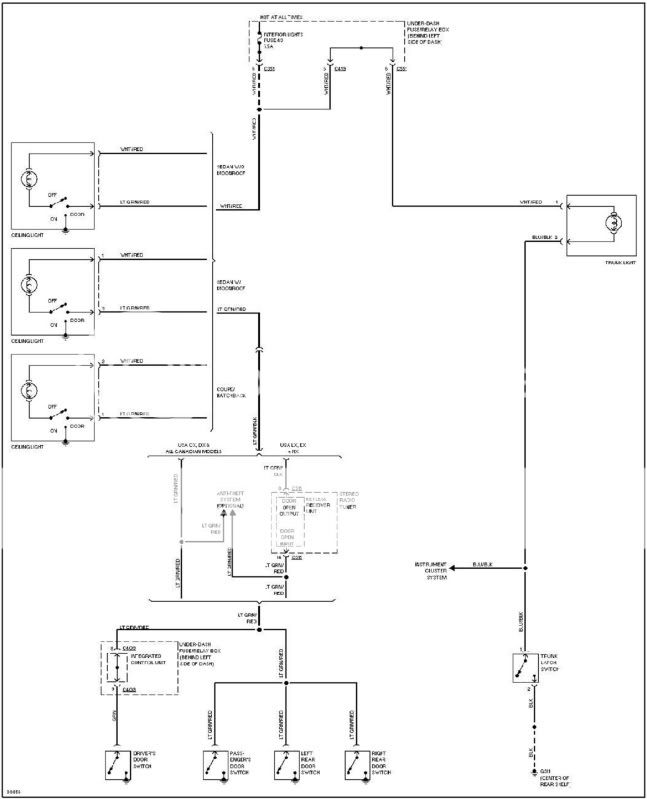
Thanks. Do you see my confusion with this now after looking at the schematic of the car? The dome light (-) runs to the passenger door, to the switch, through the floor, then behind the fuse box, which then communicates with the driver door through some kind of ICU.
Posted By: howie ll
Date Posted: September 06, 2011 at 4:06 PM
My last diagram was wrong, it will only bring on the dome light when you turn off the alarm, not on opening the door, use my previous idea with a 528t. Also we're missing the point here, dome light supervision should only activate when the alarm is switched off.
Since it doesn't do that here, assuming you did actually test, then your unit is faulty and I've no further comments...wait fleabay? Caveat emptor!
-------------
Amateurs assume, don't test and have problems; pros test first. I am not a free install service.
Read the installation manual, do a search here or online for your vehicle wiring before posting.
Posted By: zerovandez
Date Posted: September 06, 2011 at 5:31 PM
Yeah I agree. I think we've exhausted all other possibilities. I have to wrap up this portion of the project. I can live with waiting on the dome light to stop as I do not intend on using the remote start feature that often.
Howie, I would like to thank you for helping me and basically holding my hand through all of this. I seriously couldn't have done this without your help. It's people like you who make online help very pleasurable. And thanks to KP as well. You've all made this possible for me and to everyone who reads it.
I'm going to tie things up now and post pictures of my wiring. I'm pretty damn proud of myself! And I'm sure you will see me around these forums again. Thanks again, guys. Email me your paypal address, round of beers on me! Cheers!
Posted By: howie ll
Date Posted: September 06, 2011 at 6:40 PM
Before we sign off on this I have 2 questions....
1) Does your dome light stay on for say 10 seconds to a minute after shut the doors but close down immediately you lock them?
2) Do you have an "icon" on the instrument panel telling you if a door is open, usually lights up when the ignition is on.
-------------
Amateurs assume, don't test and have problems; pros test first. I am not a free install service.
Read the installation manual, do a search here or online for your vehicle wiring before posting.
Posted By: zerovandez
Date Posted: September 06, 2011 at 8:19 PM
Answers
1) Dome light only stays on during MTS mode even if I open the door and then shut it. It seems as though the brain still has control over it until it reaches it's own time limit regardless of door opening or closing. But normally, the dome lights DO turn off when closing the door and/or arming the alarm.
2) There isn't any icon on my gauge cluster which warns me that a door is open. Honda tied in the dome light to the door switches for this particular reason. Only now, my trunk light is lit when I open the doors but that's because I connected the trunk pin to the door trigger (which is connected to the dome light/door switch). I didn't bother diode isolating because it doesn't bother me.
Posted By: howie ll
Date Posted: September 07, 2011 at 12:40 AM
So, apart from the fact that;
a) Your alarm/RS is faulty or
b) You've wired something wrong such as the dome relay
c) You've hooked doors and trunk triggers together, asking for false alarms on a Honda of this age.
You're telling me there's a trunk/hatch icon but but no door open ICON.
Please look again, on later Hondas there's one each and I tie the alarm triggers to these icons, it avoids ANY door light problems.
-------------
Amateurs assume, don't test and have problems; pros test first. I am not a free install service.
Read the installation manual, do a search here or online for your vehicle wiring before posting.
Posted By: zerovandez
Date Posted: September 07, 2011 at 8:03 AM
I've double checked the dome relay. It is wired just as the installation manual suggests. I've disconnected the trunk from the door trigger and still the problem exists. I'm okay with the door triggering if the trunk/hatch is open. Yes, there is NOT a door open indicator on these vehicles. I have the entire wire schematic to my car and it doesn't list any. Again, the roof light is our indicator that a door is open. Take a look at that schematic I posted, you will see how the the common wire is lt.GREEN/ red. It's ran from the dome light down to the passenger, up to the driver and under the dash. That's what makes isolating the light so difficult; the door trigger IS the dome light wire otherwise, I would've looked for other options.
Here's what I've checked for in regard to following the instructions:
MTS mode exiting diagnostics:
If the remote start has entered the MTS mode but exits the mode after the system is armed/locked. Check these for possible causes.
The vehicle door has been opened or the security system has been triggered in your absence.
Does the vehicle have a delayed dome light circuit or does the dome light come on when the ignition is shut off? If so you may need to go to the independent door inputs of the vehicle.
If you are connected to the dome light wire in the vehicle and cannot connect the system to the individual door inputs of the vehicle due to it having normally closed door inputs, you can use the Xpresskit DTIMAZDA module or Tech Tip # 1921 at www.directechs.com to interface with these types of circuits.
The E-brake wire connected to the neutral safety input of the system loses ground when ignition is turned off or after a certain amount of time, with these vehicles unfortunately there is no workaround. The E-brake wire connected to the neutral safety input of the system has a poor ground. Clean the contacts on the switch or replace the switch.
Posted By: howie ll
Date Posted: September 07, 2011 at 9:40 AM
Sorry, just trying other possibilities, yes I'm aware it's usually GREEN/ red with blue/black or green as the trunk triggers, I was just surprised about going through a black box as that generation of Civics didn't as far as I know have a dome light delay, simple circuit, 12V+ to bulbs then grounded through the door triggers, which incidentally get very corroded if they're the sliding type.
NONE of the other reasons are at all relevant to the dome light problem, got to be the unit.
-------------
Amateurs assume, don't test and have problems; pros test first. I am not a free install service.
Read the installation manual, do a search here or online for your vehicle wiring before posting.
Posted By: howie ll
Date Posted: September 07, 2011 at 9:41 AM
P.S. I found that diagram unreadable!
-------------
Amateurs assume, don't test and have problems; pros test first. I am not a free install service.
Read the installation manual, do a search here or online for your vehicle wiring before posting.
Posted By: howie ll
Date Posted: September 07, 2011 at 9:45 AM
Hell it's your bloody car or you can't read a circuit diagram, I just had a close look at that diagram there's a warning bulb shown on the bloody instrument panel!!! pick up your door contacts there! Probable that it's in your instrument cluster but the bulb has failed.
-------------
Amateurs assume, don't test and have problems; pros test first. I am not a free install service.
Read the installation manual, do a search here or online for your vehicle wiring before posting.
Posted By: zerovandez
Date Posted: September 07, 2011 at 10:19 AM
I must be blind. All I see are ceiling light, and trunk light. Where are you seeing a warning bulb for the door trigger on that schematic? There's just a BLACK/ blue wire coming from the TRUNK pin going to the instrument panel. This is the trunk light that we already knew was present.
Posted By: howie ll
Date Posted: September 07, 2011 at 11:42 AM
It's hard to make out but right in the centre,N.B. if a car has one for the trunk, there's usually one for the doors.
-------------
Amateurs assume, don't test and have problems; pros test first. I am not a free install service.
Read the installation manual, do a search here or online for your vehicle wiring before posting.
Posted By: zerovandez
Date Posted: September 07, 2011 at 1:17 PM
I can send you the PDF's I have. You're right, it's unclear on this website. The JDM and EDM market for these cars might be different than USDM such is why you're insisting the "Door Ajar" light is there. For some Honda Integra Type R (maybe other models) 94-97, they have a Door Ajar light. There are a few people who have swapped these gauge clusters into 96-00 civic but do not have any connection to use this light. The conversion is rather simple but the point is, my civic (USDM) does not have any Door Ajar lights. I don't think any USDM Civic has it. I used to have a 93 Civic Si, I can't recall if that had it. I have the factory service manual for my car as well as the wiring diagrams. I've looked high and low for an alternate solution to no avail.
Here is a link to some credible information about the pinouts in our gauge clusters:
https://honda-tech.com/showthread.php?t=1053318
Posted By: howie ll
Date Posted: September 07, 2011 at 1:41 PM
OK, point taken, at least after you've looked at the plugs on the back of the gauges to see if there's a plug at the rear that has either a GREEN/ red or GREEN/ black wire that goes to 0v when a door is opened.
The point is, here we get JDM Civics, EDM (UK and French built) and even USDM, the Coupe. This was up to 2001. 2001-5 were similar,, but 2005 on drifted apart body and interior differences, the Integra is of course a re-bodied Civic.
-------------
Amateurs assume, don't test and have problems; pros test first. I am not a free install service.
Read the installation manual, do a search here or online for your vehicle wiring before posting.
Posted By: zerovandez
Date Posted: September 07, 2011 at 1:57 PM
You guys get all of the good stuff! We have to deal with swaps and conversions which can get expensive quick. Care to send me some parts? Lol. As for the issue at hand, I can rewire the doors and the dome light but I think that's just overkill for something rather minor. I'm going to take your suggestion and rule out that it's a faulty unit I have, bummer. Send me your paypal address, I'll enclose a payment for a 12 pack of beers. Thanks and cheers, mate!
Posted By: howie ll
Date Posted: September 07, 2011 at 2:00 PM
Very kind but don't bother, now a carton of Kent deluxe if they're still sold in the US would be nice though...don't worry it doesn't matter.
-------------
Amateurs assume, don't test and have problems; pros test first. I am not a free install service.
Read the installation manual, do a search here or online for your vehicle wiring before posting.
Posted By: zerovandez
Date Posted: September 08, 2011 at 4:54 PM
So! Looks like I have not yet laid this to rest! I've found a discovery going in the positive direction. I was reading the manual again just to see if there was something I may have missed. I checked all connections again, I made sure they were nice and secure which they are. Then I started looking at Menu 2, option 5:
Ign-controlled Dome light
1. On: the dome light output will activate when the ignition is turned off
2. Off: the dome light output will not activate when the ignition is turned off
Key words that hit me were, "...Ignition turned off." So I got out the DMM, and tested IG1 for voltage during MTS mode. My assumption, was that it dropped to 0v when in MTS, triggering the brain to turn on the dome light relay. To my surprise, It stays at 12v when initiating MTS mode. Now I'm thinking, the unit is sensing that the ignition is turning off in MTS mode thus activating the dome light per Menu 2 option 5 (on). So I programmed this option to Off, dome light will not activate when the ignition is turned off. And what do you know? It works! I don't care that the dome light doesn't turn on when key is off, it still turns on manually or when I open the door. But remote start works now!
Here's the other kicker, upon soldering wires back up, I decided I wanted to add 2 more sensors. The 506T, which will plug into the additional sensor port, and the 507M which I will need to hard wire in. Remember that issue with the 520T trigger wire during MTS procedure that I mentioned? Well the problem is showing itself. I wired in 2 diodes, stripes facing sensors 1 diode to the 520T, and the other for the anticipated 507M. Point being, this problem does exist if more than one sensor is on the instant trigger wire. I'll have to use the 528T method that Howie posted. But other than that, my remote start works without having to wait a minute for the dome light to turn off! Yeeeeaaahhhh!
Unless...I can use the blue wire on the 506T for the 507M with diodes of course...
|