Which version of HONDA4 firmware is loaded onto the DBALL? There appear to be some wiring differences between V2.08 and V2.15. If you are using D2D, then all the dashed blue wires are unnecessary.
There is a recent post on a 2006 TL and I uploaded some pictures from a 2008 TL that should help. https://www.the12volt.com/installbay/forum_posts.asp?tid=127881&KW=kreg357 There is room under the dash for the modules.
The Viper H2/10 is not needed. That function is handled by the D2D cable. H2/11 thru H2/14 are not used for your install. The Vipers Flex relay output, H3/7, can be programmed for ACC2 and connected to the TL's WHITE/ Red ACC2 wire.
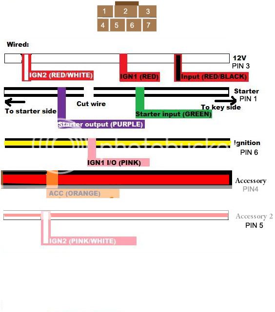
H3/1 PINK (+) IGNITION 1 INPUT/OUTPUT BLACK / YELLOW
H3/2 RED / WHITE FLEX RELAY +12V INPUT (30A FUSED) White *power for Flex relay output
H3/3 ORANGE (+) ACCESSORY OUTPUT BLACK/ Red
H3/4 VIOLET (+) STARTER OUTPUT (CAR SIDE) Black **cut for Starter Kill
H3/5 GREEN (+) STARTER INPUT (KEY SIDE) Black **cut for Starter Kill
H3/6 RED IGNITION 1 +12V INPUT (30A FUSED) White *power for IGN1 output
H3/7 PINK/WHITE (30) FLEX RELAY OUTPUT WHITE/ Red *set for ACC2, Menu3, Item 8, Opt 2
H3/8 PINK/BLACK (87a) FLEX RELAY INPUT Not Used
H3/9 RED / BLACK ACC/STARTER RELAY +12V INPUT (30A) White *power for ACC/Starter outputs
H3/10 NC No Connection
Starter Kill is optional. If you do not want this feature, do not cut the TL's Starter wire and connect only the Violet wire. Leave the H3/5 Green wire unused and insulate it.
-------------
Soldering is fun!
okay that makes sense. i was getting confused by the flex relay
btw its 2.08 firmware. any difference between the two of them
thanks for the answer
Not sure what all the Ver 2.08 to Ver 2.15 release does. The only wiring difference appears to be the Ignition1 wiring.
The vehicle has one ignition, one starter and two accessory wires at the ignition switch, all heavy gauge. The Ignition wire at the transponder immobilizer connector is thin gauge. In the Ver 2.15 Type 1 wiring guide they don't show a R/S to Ignition1 connection at the ignition switch harness, only to the thin IGN1 wire at the transponder plug. A call to DEI might be in order.
Sorry can't help too much as I prefer and use the iDatalink bypass modules.
-------------
Soldering is fun!
okay i'm confused now about the flex relay.
i try this ...
t
H3/3 ORANGE (+) ACCESSORY OUTPUT BLACK/ Red
H3/7 PINK/WHITE (30) FLEX RELAY OUTPUT WHITE/ Red *set for ACC2, Menu3, Item 8, Opt 2
but the car wouldnt start. i had the menu and everythign then i try menu 3, item 8 , opt 1
i switch PINK/WHITE to slot location H3/1 and PINK to slot H3/7...this mode is for 2nd ingition but my car starts here instead of 2nd acc....but the only thing that does work is the radio because of acc1
If I understand correctly, your new wiring that starts the car looks like this :
H3/1 PINK (+) IGNITION 1 INPUT/OUTPUT WHITE/ Red ( Cars ACC2 wire )
H3/2 RED / WHITE FLEX RELAY +12V INPUT (30A FUSED) White *power for Flex relay output
H3/3 ORANGE (+) ACCESSORY OUTPUT BLACK/ Red ( cars ACC1 wire )
H3/4 VIOLET (+) STARTER OUTPUT (CAR SIDE) Black **cut for Starter Kill
H3/5 GREEN (+) STARTER INPUT (KEY SIDE) Black **cut for Starter Kill
H3/6 RED IGNITION 1 +12V INPUT (30A FUSED) White *power for IGN1 output
H3/7 PINK/WHITE (30) FLEX RELAY OUTPUT BLACK / YELLOW *set for IGN2, Menu3, Item 8, Opt 1 ( cars IGN1 wire )
H3/8 PINK/BLACK (87a) FLEX RELAY INPUT Not Used
H3/9 RED / BLACK ACC/STARTER RELAY +12V INPUT (30A) White *power for ACC/Starter outputs
H3/10 NC No Connection
The Flex relay and its' programming seem to be fine. The Ignition1 output from the Viper H3/1 Pink wire seems to have a problem.
Check the 30A fuse on the Red wire ( H3/6 ). ( verify all fuses )
Verify that H3/6 is connected to +12V Constant ( White ) and has +12v at the Red wires connector at the Viper H3 plug. ( use a DMM and verify good power at all fused input wires, Red, RED / White, RED / Black, at the Vipers H3 connector )
Finally, put a DMM on the H3/1 Pink wire and verify +12v output during a remote start.
-------------
Soldering is fun!
If it helps this is what I made when doing my install on my 2006 TL. That connector is most likely the same too. Oh and it works!