understanding door lock schematic ford
Printed From: the12volt.com
Forum Name: Car Security and Convenience
Forum Discription: Car Alarms, Keyless Entries, Remote Starters, Immobilizer Bypasses, Sensors, Door Locks, Window Modules, Heated Mirrors, Heated Seats, etc.
URL: https://www.the12volt.com/installbay/forum_posts.asp?tid=128821
Printed Date: March 11, 2026 at 6:55 AM
Topic: understanding door lock schematic ford
Posted By: boulderguy
Subject: understanding door lock schematic ford
Date Posted: October 12, 2011 at 1:50 PM
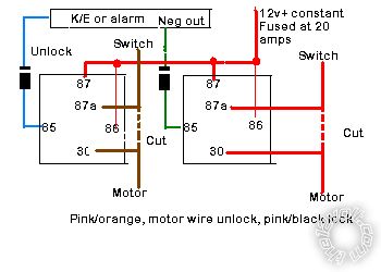
I'm doing the door locks for a keyless entry on a 2002 Ford Econoline E-350 diesel. The wires mentioned in the chart are brown & red at the kick panel which I've located. When tested, it looks like a low-voltage type C. This schematic below appears accurate but I don't understand schematics very well.
The system can do either + or - triggers for lock/unlock. Can anyone read this schematic & guide me thru?

Replies:
Posted By: howie ll
Date Posted: October 12, 2011 at 6:51 PM
Looks like a 5 wire reversing polarity to me.
Use this diagram and 2 relays and diodes or a DEI 451 module, set your system for NEG outputs:- 5_wire_locks.bmp
Passenger side, either in door or more conveniently, the passenger kick well, where those cables go into the interior; note the colour changes, brown to pink/light green and red to pink / YELLOW. ------------- Amateurs assume, don't test and have problems; pros test first. I am not a free install service.
Read the installation manual, do a search here or online for your vehicle wiring before posting.
Posted By: boulderguy
Date Posted: October 12, 2011 at 8:00 PM
Got it, thanks, and the diagram's perfect. I figured I needed some relays & ordered a handful today, I'm already up to 3 in this remote starter - damn diesel!
I located where the brown & red become pink etc in the passenger kick & tested, I get +12v on each for unlock or lock, as I would expect. But then I tried to test by feeding +12v directly into them (fused that test wire at 10a) & immediately cooked the fuse - does this sound right?
Posted By: blanx218
Date Posted: October 12, 2011 at 9:24 PM
They are 5wire reverse polarity and you need to use relays
Posted By: Ween
Date Posted: October 12, 2011 at 9:31 PM
yes, the fuse will blow. if you look at the passenger front door switch in the schematic, the brown and red leads rest at ground. we know what happens when you connect +12 volts directly to ground. the relays, wired in properly, will isolate the grounds, allowing the door lock motors to operate.
Posted By: boulderguy
Date Posted: October 12, 2011 at 11:05 PM
OK, I see the isolation in the relay layout now. Wiring up the relays is simple enough but one question, the diagram lists motor side & switch side of the wire. Since I'm cutting into the wires at the passenger kick, this sounds like a dumb question, but since the switch & motor are both in the passenger door I'm a little confused. Can someone dummy-proof this for me?
Does
"motor" = "passenger door" and
"switch" = "towards engine"
in this case, or reversed?
Also, are the diodes significant? I don't see how it's needed with two separate lock/unlock leads from the KE.
Posted By: howie ll
Date Posted: October 13, 2011 at 12:55 AM
Blast you Mr. Ween and the 5 (6 over the next couple of weeks, we go out of summer time 2 weeks before). You're always getting the correct answers in before me. 
As for the original poster; cut those leads once you found them, then test each side by toggling that passenger door switch. The cut ends that show live on the two are the switch sides.
The diodes are there to protect your K/E from relay on-rush or back voltage shut down spike. Unless your K/E has built in relays*...in which case you won't need external relays anyway, use them, better safe than sorry.
*If you have 6 lock wires you have built in relays and you won't need external relays. ------------- Amateurs assume, don't test and have problems; pros test first. I am not a free install service.
Read the installation manual, do a search here or online for your vehicle wiring before posting.
Posted By: boulderguy
Date Posted: October 13, 2011 at 2:26 AM
^^ With 7000+ posts I'd say you're winning the war Howie :)
Anyone got a good trick for connecting inline diodes that doesn't involve solder? 'cos I suck at solder. I've crimped them between a couple butt connectors before. Whoa, that sounds weird...
Thanks all for the input, I think I'm all set.
Posted By: howie ll
Date Posted: October 13, 2011 at 2:41 AM
Yes it does doesn't it but 12 years ago I used to do the same thing, butt butt butt. Sorry poor Peter Sellars joke.
This is my trick:-
Treat the leads as wire and twist them together with the bare wire (i.e. stripped 1/4-1/2"), then solder. You need 3/16" or 3.2 mm heat shrink or a good tape such as Scotch 33+. Heat shrink is better and neater.
Remember the trick is to apply the heat to the joint and then let the solder flow into it.
-------------
Amateurs assume, don't test and have problems; pros test first. I am not a free install service.
Read the installation manual, do a search here or online for your vehicle wiring before posting.
Posted By: groundzero2010
Date Posted: October 13, 2011 at 8:04 AM
boulderguy wrote:
OK, I see the isolation in the relay layout now. Wiring up the relays is simple enough but one question, the diagram lists motor side & switch side of the wire. Since I'm cutting into the wires at the passenger kick, this sounds like a dumb question, but since the switch & motor are both in the passenger door I'm a little confused. Can someone dummy-proof this for me?
Does
"motor" = "passenger door" and
"switch" = "towards engine"
in this case, or reversed?
Also, are the diodes significant? I don't see how it's needed with two separate lock/unlock leads from the KE.
You may not have to remember this but I always remember the relay configuration by the "switch" side of the cut wire goes in the "center". Kind of silly because neither start with the same letter they just have the "s" sound. And yes your diodes are perfect. You want the ground to travel from the alarm through to the relays, the line being closest to your (-) output on your alarm/keyless entry allows the pass through of (-) output. However the negative can't travel back upstream from the relay to the alarm. Positive (+) travels the exact opposite through a diode.
|