remote start, 07 tacoma
Printed From: the12volt.com
Forum Name: Car Security and Convenience
Forum Discription: Car Alarms, Keyless Entries, Remote Starters, Immobilizer Bypasses, Sensors, Door Locks, Window Modules, Heated Mirrors, Heated Seats, etc.
URL: https://www.the12volt.com/installbay/forum_posts.asp?tid=133430
Printed Date: May 28, 2024 at 7:54 PM
Topic: remote start, 07 tacoma
Posted By: clemsonscj
Subject: remote start, 07 tacoma
Date Posted: January 25, 2013 at 11:29 PM
Putting a remote start/security system in my 07 Tacoma. What is the dome light supervision? Is it worth hooking up?
Replies:
Posted By: howie ll
Date Posted: January 25, 2013 at 11:58 PM
No. If the vehicle's dome light stays on for up to a minute after you shut the door but shuts down immediately you lock it then like most Toyotas you already have it and you connect the alarm NEG door trigger to the wire marked dome supervision.
-------------
Amateurs assume, don't test and have problems; pros test first. I am not a free install service.
Read the installation manual, do a search here or online for your vehicle wiring before posting.
Posted By: clemsonscj
Date Posted: January 26, 2013 at 12:04 AM
So I can hook the door trigger to the dome light wire as a door monitor?
Posted By: howie ll
Date Posted: January 26, 2013 at 12:13 AM
Yes, providing it already works as I described above.
-------------
Amateurs assume, don't test and have problems; pros test first. I am not a free install service.
Read the installation manual, do a search here or online for your vehicle wiring before posting.
Posted By: clemsonscj
Date Posted: January 26, 2013 at 12:18 AM
That is how it works, but I thought the door trigger is a neg input and the dome light is positive. Maybe it's neg though idk
Posted By: howie ll
Date Posted: January 26, 2013 at 12:27 AM
No such thing as maybe, TEST, OK I'm winding you up.
Blue (-) NEG dash fuse box, black 13 pin plug (1E), pin 9.
-------------
Amateurs assume, don't test and have problems; pros test first. I am not a free install service.
Read the installation manual, do a search here or online for your vehicle wiring before posting.
Posted By: clemsonscj
Date Posted: January 26, 2013 at 12:37 AM
Ok I just didn't have the manual in front of me here. But I'll be metering everything when I do it tomorrow.
Posted By: howie ll
Date Posted: January 26, 2013 at 12:51 AM
Good, with out trying to sound facetious, patronising or condescending please please re-read my signature line. 
We get more problems arising from people assuming and not testing than anything else. ------------- Amateurs assume, don't test and have problems; pros test first. I am not a free install service.
Read the installation manual, do a search here or online for your vehicle wiring before posting.
Posted By: clemsonscj
Date Posted: January 26, 2013 at 7:50 AM
I'm in the middle of hooking up a remote start on my 07 Tacoma. I'm getting confused by the wording on the Viper harness diagram, so I need some quick help. Can you take a look at these 2 links, one being the wiring for my Tacoma and the other being the install instructions for the Viper unit, and let me know which wires go to which between the 2 (only for the 10-pin heavy-gauge remote start harness):
https://www.bulldogsecurity.com/bdnew/vehiclewiringdiagrams.asp (you'll have to select "Toyota" and then scroll down to where it says "2005-2008" under Tacoma)
https://www.12voltdistributors.com/wp-content/uploads/2012/09/Viper_5904V_Installation_Guide.pdf
Thanks in advance.
Posted By: kreg357
Date Posted: January 26, 2013 at 8:09 AM
H3/1 PINK (+) IGNITION 1 INPUT/OUTPUT BLACK/ red (+) ignition switch, white 8 pin plug, pin 6
H3/2 RED / WHITE (+) FUSED (30A) IGNITION 2 WHITE/ red (30A) (+) ignition switch, white 8 pin plug, pin 5
H3/3 ORANGE (+) ACCESSORY OUTPUT WHITE/ green + ignition switch, white 8 pin plug, pin 2
H3/4 VIOLET (+) STARTER OUTPUT (CAR SIDE) GREEN/ black + ignition switch, white 8 pin plug, pin 7
H3/5 GREEN (+) STARTER INPUT (KEY SIDE) GREEN/ black + ignition switch, white 8 pin plug, pin 7
H3/6 RED (+) FUSED (30A) IGNITION 1 INPUT WHITE/ red (30A) (+) ignition switch, white 8 pin plug, pin 5
H3/7 PINK/WHITE (+) IGNITION 2 / FLEX RELAY OUTPUT blue / YELLOW + ignition switch, white 8 pin plug, pin 1 *** Set to IGN2
H3/8 PINK/BLACK (+) FLEX RELAY INPUT 87A
H3/9 RED / BLACK (+) FUSED (30A) ACC/STARTER INPUT WHITE/ red (30A) (+) ignition switch, white 8 pin plug, pin 5
H3/10 NC (no connection)
You will need an additional 30/40 Amp SPDT relay with 20 Amp fuse to power the Tacoma's Starter2 circuit. Wire as follows :
Relay Pin 85 to Viper Purple (-) 200mA Starter Output ( thin wire )
Relay Pin 86 and 87 to +12V constant ( WHITE/ red (30A) (+) ignition switch, white 8 pin plug, pin 5 ) thru 20 Amp fuse
Relay Pin 30 to Tacoma BLACK/ white (+) ignition switch, white 8 pin plug, pin 3
Relay P{in 87A not used - insulate ------------- Soldering is fun!
Posted By: howie ll
Date Posted: January 26, 2013 at 8:17 AM
Here's an over view NOTE colours may not be the same, not sure which Toyota I did it for. E83_tacoma_wiring.bmp------------- Amateurs assume, don't test and have problems; pros test first. I am not a free install service.
Read the installation manual, do a search here or online for your vehicle wiring before posting.
Posted By: andeyhall
Date Posted: January 26, 2013 at 8:37 AM
Thanks guys! tons of help!
Posted By: clemsonscj
Date Posted: January 26, 2013 at 8:48 AM
kreg357 wrote:
H3/1 PINK (+) IGNITION 1 INPUT/OUTPUT BLACK/ red (+) ignition switch, white 8 pin plug, pin 6
H3/2 RED / WHITE (+) FUSED (30A) IGNITION 2 WHITE/ red (30A) (+) ignition switch, white 8 pin plug, pin 5
H3/3 ORANGE (+) ACCESSORY OUTPUT WHITE/ green + ignition switch, white 8 pin plug, pin 2
H3/4 VIOLET (+) STARTER OUTPUT (CAR SIDE) GREEN/ black + ignition switch, white 8 pin plug, pin 7
H3/5 GREEN (+) STARTER INPUT (KEY SIDE) GREEN/ black + ignition switch, white 8 pin plug, pin 7
H3/6 RED (+) FUSED (30A) IGNITION 1 INPUT WHITE/ red (30A) (+) ignition switch, white 8 pin plug, pin 5
H3/7 PINK/WHITE (+) IGNITION 2 / FLEX RELAY OUTPUT blue / YELLOW + ignition switch, white 8 pin plug, pin 1 *** Set to IGN2
H3/8 PINK/BLACK (+) FLEX RELAY INPUT 87A
H3/9 RED / BLACK (+) FUSED (30A) ACC/STARTER INPUT WHITE/ red (30A) (+) ignition switch, white 8 pin plug, pin 5
H3/10 NC (no connection)
You will need an additional 30/40 Amp SPDT relay with 20 Amp fuse to power the Tacoma's Starter2 circuit. Wire as follows :
Relay Pin 85 to Viper Purple (-) 200mA Starter Output ( thin wire )
Relay Pin 86 and 87 to +12V constant ( WHITE/ red (30A) (+) ignition switch, white 8 pin plug, pin 5 ) thru 20 Amp fuse
Relay Pin 30 to Tacoma BLACK/ white (+) ignition switch, white 8 pin plug, pin 3
Relay P{in 87A not used - insulate
Thanks for all the help man! Last question just to clarify 2 things...H3/8 is not used right? And also, the guy that posted after you about the relay indicated a diode between pins 86 and 85 of the relay. Is the diode necessary in this case? Hopefully not lol, as I had having to fool with those damn things.
Posted By: howie ll
Date Posted: January 26, 2013 at 8:53 AM
Do you want to tell him why it should be mandatory Kregg?
-------------
Amateurs assume, don't test and have problems; pros test first. I am not a free install service.
Read the installation manual, do a search here or online for your vehicle wiring before posting.
Posted By: kreg357
Date Posted: January 26, 2013 at 9:01 AM
Yes, H3/8 is not used for your install.
The diode ( code name IHOH Quencher  ) is for quenching spikes generated by the relays coil. It is a wise safety precaution if your R/S unit's output is not designed to safely drive a relay. While I haven't read anything that specifically states the Vipers outputs are designed and protected for relay use, they do state in the install guide that they are for relay use. Other installers have posted that they never use the coil diode and have not had any problems. The 1N4004 or 1N4007 diodes are available at RadioShack in 3 packs for less than $3 and soldering one on takes a minute or so. ) is for quenching spikes generated by the relays coil. It is a wise safety precaution if your R/S unit's output is not designed to safely drive a relay. While I haven't read anything that specifically states the Vipers outputs are designed and protected for relay use, they do state in the install guide that they are for relay use. Other installers have posted that they never use the coil diode and have not had any problems. The 1N4004 or 1N4007 diodes are available at RadioShack in 3 packs for less than $3 and soldering one on takes a minute or so. ------------- Soldering is fun!
Posted By: clemsonscj
Date Posted: January 26, 2013 at 9:05 AM
Soldering and I are like ex's...we prefer not to have anything to do with each other unless necessary, preferably an absolute emergency and no loss lol.
Posted By: clemsonscj
Date Posted: January 26, 2013 at 9:06 AM
less, not loss
Posted By: howie ll
Date Posted: January 26, 2013 at 9:15 AM
How do you intend to join your wires?
-------------
Amateurs assume, don't test and have problems; pros test first. I am not a free install service.
Read the installation manual, do a search here or online for your vehicle wiring before posting.
Posted By: kreg357
Date Posted: January 26, 2013 at 9:16 AM
Ahh, man. You're killing me.  Look at my byline. Soldering really is fun, just gotta practice a lot. Look at my byline. Soldering really is fun, just gotta practice a lot.  Ideally, you should solder all your connections. Those T-Taps and Scotch-Locks are nothing but trouble down the road. Ideally, you should solder all your connections. Those T-Taps and Scotch-Locks are nothing but trouble down the road.
More info on relay coil quenching diodes : https://www.bcae1.com/relays.htm About half way down the page.
Quenching Diodes:
Anytime that a relay coil is driven by a circuit that is not specifically designed to drive a relay, you should use a quenching/suppression
diode connected in parallel with the relay coil. The diagram below will show the connection of the diode. Initially, you may think the diode
serves no purpose because the voltage applied to the relay cannot pass through the diode. This is true when the relay is energized. The
diode comes into play when the power source is removed from the relay coil. When power is applied to the relay coil, a magnetic field is
created and energy is stored in the coil. When power is removed, the magnetic field collapses causing a reverse voltage to be generated
(it's called inductive kickback or back EMF). The back EMF can easily reach 200 volts. The diode will absorb the reverse voltage spike.
This voltage, if not absorbed by the diode, will cause premature failure of switch contacts and may cause the failure of power switching
transistors. You can use virtually any type of rectifier or switching diode (i.e. 1N4001, 1N4002, 1N400x... or Radio Shack part #s 276-1101,
276-1102, 276-1103, 276-1104).
Very cheap insurance for your very expensive Viper system. ------------- Soldering is fun!
Posted By: howie ll
Date Posted: January 26, 2013 at 9:32 AM
First point I did once about 5 months ago tell someone to use diodes on a Viper he "forgot" and lost his lock/unlock and aux. He was begging for the next month for anyone to come up with a work around, obviously his supplier found out and told him where to go.
IMO diodes on trigger wires to relays should be mandatory.
In fact had you read your Viper instructions owners' manual, they actually tell you to diode aux and NEG start ignition and ACC wires from plug H2 when feeding relays.
In the General Section are three lengthy but informative threads on "how to" and "why" you should solder.
The back EMP on a relay shut-down from the coil generates about 250 volts.
1N4004 has an inverse value of 400 volts so it should work fine.
Using T-Taps = inferior electrical joint with a higher contact resistance if it even makes the join.
Vibration shakes them apart.
Moisture induced corrosion will finally kill them off after about 3 months.
If you can't solder or test properly don't even try this install.
-------------
Amateurs assume, don't test and have problems; pros test first. I am not a free install service.
Read the installation manual, do a search here or online for your vehicle wiring before posting.
Posted By: clemsonscj
Date Posted: January 26, 2013 at 11:02 AM
kreg357 wrote:
Ahh, man. You're killing me. Look at my byline. Soldering really is fun, just gotta practice a lot. Ideally, you should solder all your connections. Those T-Taps and Scotch-Locks are nothing but trouble down the road.
More info on relay coil quenching diodes : https://www.bcae1.com/relays.htm About half way down the page.
Quenching Diodes:
Anytime that a relay coil is driven by a circuit that is not specifically designed to drive a relay, you should use a quenching/suppression
diode connected in parallel with the relay coil. The diagram below will show the connection of the diode. Initially, you may think the diode
serves no purpose because the voltage applied to the relay cannot pass through the diode. This is true when the relay is energized. The
diode comes into play when the power source is removed from the relay coil. When power is applied to the relay coil, a magnetic field is
created and energy is stored in the coil. When power is removed, the magnetic field collapses causing a reverse voltage to be generated
(it's called inductive kickback or back EMF). The back EMF can easily reach 200 volts. The diode will absorb the reverse voltage spike.
This voltage, if not absorbed by the diode, will cause premature failure of switch contacts and may cause the failure of power switching
transistors. You can use virtually any type of rectifier or switching diode (i.e. 1N4001, 1N4002, 1N400x... or Radio Shack part #s 276-1101,
276-1102, 276-1103, 276-1104).
Very cheap insurance for your very expensive Viper system.
Alright I took a trip to RadioShack and bought me a diode and some solder and have been slaving ever since lol. But I have another issue. I guess I thought I knew what all the wires went to on the other H1 and H2 harness. The only wires I'm not sure about on the H1 harness as far as what they need to be hooked up to are the 2 parking light wires. On the H2 harness, the easiest thing to do would probably be if you could tell me which ones I don't need, and if I have questions from there I can ask on a wire-by-wire basis. Much much appreciated! Thanks guys!
Posted By: kreg357
Date Posted: January 26, 2013 at 11:21 AM
See, soldering is fun!
Which model Viper do you have? There are some differences with the H1 and H2 harnesses ( the wire colors and names usually stay the same ).
For your Tacoma, I would set the Viper's internal jumper/fuse to (-) Parking Light Output and connect to this wire.
Use the Viper's White Parking Light Output wire. The other WHITE/ Brown Parking Isolation wire is unused.
Parking Lights (-) green (-) @ headlight switch, white 20 pin plug, pin 18 ------------- Soldering is fun!
Posted By: clemsonscj
Date Posted: January 26, 2013 at 11:27 AM
Viper 5904. What you just said covers the H1 harness. All I have left is the H2 harness and the same bypass module.
Posted By: howie ll
Date Posted: January 26, 2013 at 11:49 AM
And what was the by-pass module?
I can't seem to find any mention of one so far.
Without that knowledge here are your H2 connections.
H2/1 N/A
H2/2 Grounded if auto, parking brake switch (wire) if manual.
H2/3 Keysense, to GREEN/ black (-) ignition key switch, white 2 pin plug, pin 1
H2/4 Use key sense
H2/5 N/A
H2/6 Door trigger input to blue as my earlier post.
H2/7 N/A
H2/8 If required join to GREEN/ red dash fuse box, white 18 pin plug (1C), pin 10.
H2/9 to by-pass blue trigger.
H2/10 N/A
H2/11 N/A
H2/12 N/A
H2/13 N/A
H2/14 N/A
H2/15 N/A
H2/16 To blue, dash fuse box, white 13 pin plug (1D), pin 13.
H2/17 Hood pin (you install).
H2/18 to the 2nd. starter relay as above 1N4004 diode!
H2/19 trunk pin or load area sensor.
H2/20 N/A
H2/21 N/A
H2/22 N/A
H2/23 Tach, to BLACK/ white, data link connector, white 16 pin plug, pin 9.
H2/24 N/A
-------------
Amateurs assume, don't test and have problems; pros test first. I am not a free install service.
Read the installation manual, do a search here or online for your vehicle wiring before posting.
Posted By: kreg357
Date Posted: January 26, 2013 at 11:51 AM
Sorry, just noticed your link to a 5904 install guide...
Does your Tacoma have the Factory Alarm?
Also, not sure about the transponder bypass module.
H2/1 PINK/WHITE (-) 200mA IGNITION/FLEX RELAY CONTROL OUTPUT Not Used
H2/2 BLACK/ WHITE (-) NEUTRAL SAFETY INPUT Chassis Ground if Auto Trans
H2/3 BLUE/WHITE (-) 200mA 2ND STATUS /REAR DEFOGGER OUTPUT Not Used ( if Factory Alarm use for Keysense )
H2/4 GREEN/ BLACK (-) 200mA OEM ALARM DISARM OUTPUT Not Used unless you have Factory Alarm
H2/5 RED / WHITE (-) 200mA TRUNK RELEASE OUTPUT Not Used
H2/6 GREEN (-) DOOR TRIGGER INPUT (N/C* OR N/O) More diodes!!!  See Note 5 See Note 5
H2/7 BLACK / YELLOW (-) 200mA DOME LIGHT SUPERVISION OUTPUT Answered by Howard
H2/8 BROWN / BLACK (-) 200mA HORN HONK OUTPUT GREEN/ red (-) dash fuse box, white 18 pin plug (1C), pin 10
H2/9 DARK BLUE (-) 200mA STATUS OUTPUT Bypass Module GWR if going W2W
H2/10 PINK (-) 200mA IGNITION 1 OUTPUT Not Used
H2/11 WHITE/ BLACK (-) 200mA AUX 3 OUTPUT Not Used
H2/12 VIOLET (+) DOOR TRIGGER INPUT Not Used See (-) Door Trigger
H2/13 WHITE/ VIOLET (-) 200mA AUX 1 OUTPUT Not Used
H2/14 VIOLET/BLACK (-) 200mA AUX 2 OUTPUT Not Used
H2/15 ORANGE / BLACK (-) 200mA AUX 4 OUTPUT Not Used
H2/16 BROWN (+) BRAKE SHUTDOWN INPUT blue (+) dash fuse box, white 13 pin plug (1D), pin 13
H2/17 GREY (-) HOOD PIN INPUT (N/C OR N/O) Viper supplied hood pin
H2/18 VIOLET / YELLOW (-) 200mA STARTER OUTPUT To external relay Pin 85
H2/19 BLUE (-) TRUNK PIN/ INSTANT TRIGGER INPUT (N/C OR N/O) Not Used
H2/20 GREY/BLACK (-) DIESEL WAIT TO START INPUT Not Used
H2/21 WHITE/ BLUE (-) REMOTE START/ TURBO TIMER ACTIVATION INPUT Not Used
H2/22 ORANGE (-) 200mA ACCESSORY OUTPUT Not Used
H2/23 VIOLET/WHITE TACHOMETER INPUT BLACK/ white (a)c OBD2 pin 9
H2/24 GREEN / WHITE (-) 200mA OEM ALARM ARM OUTPUT Not Used unless you have Factory Alarm
NOTE #5; the DRIVERS DOOR is a GREEN/ YELLOW (-) in the 18-pin plug, pin 7, the
PASSENGER DOOR is a RED / BLACK (-) in a 22-pin plug, pin 8, the REAR DOORS
are a PINK/BLACK (-) in an 18-pin plug pin 6, when connecting to an ALARM SYSTEM,
use all (3) DOOR TRIGGER wires and DIODE ISOLATE, to connect, See DIAGRAM :
https://www.bulldogsecurity.com/diagrams/extrainfo/diagrams/14301_TACOMA_(-)%20NEGATIVE%20DOOR%20PIN%20ISOLATION%20CIRCUIT.pdf ------------- Soldering is fun!
Posted By: howie ll
Date Posted: January 26, 2013 at 12:12 PM
Did you write your answer at the same time K? Look at the time stamps!
Note we both picked up on the transponder.
N.B. since about 99 I've always gone to the dome trigger on Toyotas, never needed separate door triggers.
-------------
Amateurs assume, don't test and have problems; pros test first. I am not a free install service.
Read the installation manual, do a search here or online for your vehicle wiring before posting.
Posted By: kreg357
Date Posted: January 26, 2013 at 12:17 PM
I'm still a slow typist. Thank goodness for spell check.
Dome light delays scare me...
------------- Soldering is fun!
Posted By: clemsonscj
Date Posted: January 26, 2013 at 12:21 PM
I don't think my truck has the factory alarm system. How would I know for sure? Either way, the bypass module I'm using is the FLCAN from flashlogic. So do I use H2/3 or H2/4 for keysense?
Posted By: howie ll
Date Posted: January 26, 2013 at 12:24 PM
Why? Forget making one, the vehicle already has one. All I'm saying is connect the vehicle dome light trigger wire to the DEI green door trigger, see my first post on this thread. Yes it works that way no need for 4 extra diodes (did I really say that?).
Done it that way many many times, no probs.
-------------
Amateurs assume, don't test and have problems; pros test first. I am not a free install service.
Read the installation manual, do a search here or online for your vehicle wiring before posting.
Posted By: howie ll
Date Posted: January 26, 2013 at 12:27 PM
Either, one to the by-pass, one to the keysense, better safe than sorry.
Leave a window open so you can reach in, use the factory remote, press lock twice, wait 30 seconds then reach in and open a door. No noise = no factory alarm.
-------------
Amateurs assume, don't test and have problems; pros test first. I am not a free install service.
Read the installation manual, do a search here or online for your vehicle wiring before posting.
Posted By: kreg357
Date Posted: January 26, 2013 at 12:31 PM
The FLCAN flashed with the FLC-AL(TB)-TL firmware handles the keysense for you. Just follow the Type 2
install diagram. If you have the FLCAN to Viper DBI D2D harness, you can go D2D and not use the Vipers
Blue (-) 200mA Status Output wire.
-------------
Soldering is fun!
Posted By: clemsonscj
Date Posted: January 26, 2013 at 12:43 PM
howie ll wrote:
Either, one to the by-pass, one to the keysense, better safe than sorry.
Leave a window open so you can reach in, use the factory remote, press lock twice, wait 30 seconds then reach in and open a door. No noise = no factory alarm.
Ok so no factory alarm for me...so I only need one of those wires?
Posted By: howie ll
Date Posted: January 26, 2013 at 12:47 PM
See Kregg's last post, he's more familiar with the by-pass than me.
-------------
Amateurs assume, don't test and have problems; pros test first. I am not a free install service.
Read the installation manual, do a search here or online for your vehicle wiring before posting.
Posted By: clemsonscj
Date Posted: January 26, 2013 at 12:49 PM
kreg357 wrote:
The FLCAN flashed with the FLC-AL(TB)-TL firmware handles the keysense for you. Just follow the Type 2
install diagram. If you have the FLCAN to Viper DBI D2D harness, you can go D2D and not use the Vipers
Blue (-) 200mA Status Output wire.
Oh so with the FLCAN I don't need H2/3 or H2/4?
Posted By: kreg357
Date Posted: January 26, 2013 at 1:03 PM
Correct. If no Factory Alarm, you won't need H2/4 or H2/24. The FLCAN will connect to the Tacoma's Keysense
wire. Additionally, if you connect the Viper to the FLCAN with the D2D harness, you won't need H2/9.
No AutoHeadlights, right? ------------- Soldering is fun!
Posted By: clemsonscj
Date Posted: January 26, 2013 at 1:13 PM
No, these trucks do not have an auto headlight option. But what about H2/3? Is it out of the equation now? Because the bypass module is showing it needs a (+) ignition input from the remote start module, but I don't see a (+) ignition wire on my module diagram...
Posted By: kreg357
Date Posted: January 26, 2013 at 1:29 PM
That (+) Ignition Input that the FLCAN is looking for will be the same H3/1 Pink Ignition Output wire that you will be
connecting to the Tacoma's BLACK/ Red Ignition1 wire. I usually mate the bypass module to the R/S brain during bench
prep and make the connection then.
-------------
Soldering is fun!
Posted By: clemsonscj
Date Posted: January 26, 2013 at 1:36 PM
So I can just solder it in with H3/1?
Posted By: kreg357
Date Posted: January 26, 2013 at 1:59 PM
Yes. Here is an example, using an ADS AL CA ( same as FLCAN ) and an Ultra Start brain.
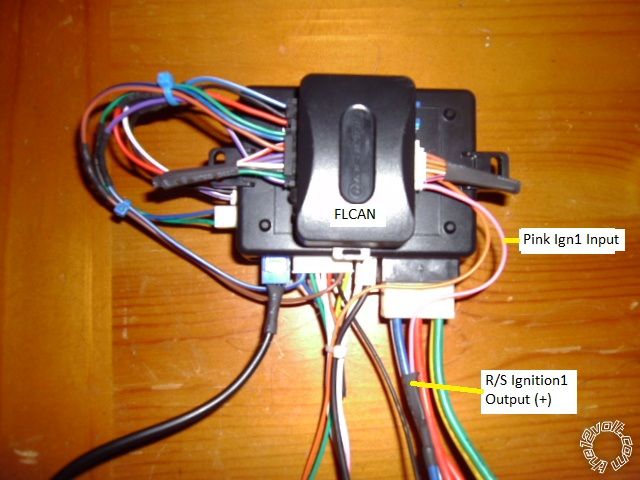
------------- Soldering is fun!
Posted By: clemsonscj
Date Posted: January 26, 2013 at 2:26 PM
Ok got everything wired up and it will lock and unlock, but will not remote start. It sends a message back to the remote saying remote start is unavailable and the lights flash 7 times.
Posted By: clemsonscj
Date Posted: January 26, 2013 at 2:49 PM
Apparently it's in manual mode and there's some error there. But I also noticed that the status LED doesn't do anything...and I still can't figure why my bitwriter won't communicate with the module. Power and ground are working fine and like I said, it locks and unlocks just fine.
Posted By: kreg357
Date Posted: January 26, 2013 at 3:26 PM
Viper 5904, eh? What Version Prom Chip in the BitWriter? Think you need at least V2.7.
-------------
Soldering is fun!
Posted By: clemsonscj
Date Posted: January 26, 2013 at 3:31 PM
It is 2.7
Posted By: kreg357
Date Posted: January 26, 2013 at 4:12 PM
Should be good to go.
-------------
Soldering is fun!
Posted By: clemsonscj
Date Posted: January 26, 2013 at 5:20 PM
kreg357 wrote:
Should be good to go.
Haven't figured out the bitwriter yet. As cheap as that are, I just went ahead and ordered the upgraded chip to see if that's the issue. But in the mean time, I got it out of manual mode and figured out how to change menu options with the antenna button so everything is working 100% right now. We'll see what happens with the bitwriter down the road. To be honest, I have that module so crammed up behind the dash, I really don't know if I wanna fish it out just for the sake of seeing if it works...
Posted By: howie ll
Date Posted: January 26, 2013 at 6:08 PM
Never needed a Bitwriter, once you get used to the manual programming it's far quicker to use that.
Why on earth would you use a Bitwriter or Eprom programmer to the uninitiated for one install.
Can't see anything you'd need it for.
-------------
Amateurs assume, don't test and have problems; pros test first. I am not a free install service.
Read the installation manual, do a search here or online for your vehicle wiring before posting.
Posted By: clemsonscj
Date Posted: January 26, 2013 at 6:25 PM
howie ll wrote:
Never needed a Bitwriter, once you get used to the manual programming it's far quicker to use that.
Why on earth would you use a Bitwriter or Eprom programmer to the uninitiated for one install.
Can't see anything you'd need it for.
Well I had originally gotten it when I had a diesel. You can program certain custom options rather than rounded defaults. But anywho, I'm having one last slight issue. It takes 2, sometimes 3 tries for it to start. I've upped the crank time to 1.2 seconds and still the same problem. It seems like it's not cranking the full amount of time before it stops. I've got a feeling it's because I did the virtual tach rather than hard wiring the tachometer. You think this is throwing some things off?
Posted By: howie ll
Date Posted: January 26, 2013 at 6:42 PM
This is where I get kicked out again Kregg but really clemsonscj, in an earlier post I stressed mistakes were made because people didn't read the instructions if you had you would have known to programme for auto and tach, open door, ign on, off hold button for three chirps press once hold, press remote, 2 chirps = auto.
Repeat, press twice, hold, push remote 3 times, 4 chirps. Tach.
I've only ever installed 2 units but I just did that from memory.
Hell I even gave you the tach wire colour and location, it's not even under the hood it's under the driver dash where you'd have done all your work!
Along with using T-Taps not wanting to use diodes, pure laziness.
Got to be one of the all time easy vehicles to do.
And 5 pages so far. I'm pretty certain that though he's more diplomatic than me Kregg agrees with what I'm saying.
-------------
Amateurs assume, don't test and have problems; pros test first. I am not a free install service.
Read the installation manual, do a search here or online for your vehicle wiring before posting.
Posted By: clemsonscj
Date Posted: January 26, 2013 at 10:12 PM
howie ll wrote:
This is where I get kicked out again Kregg but really clemsonscj, in an earlier post I stressed mistakes were made because people didn't read the instructions if you had you would have known to programme for auto and tach, open door, ign on, off hold button for three chirps press once hold, press remote, 2 chirps = auto.
Repeat, press twice, hold, push remote 3 times, 4 chirps. Tach.
I've only ever installed 2 units but I just did that from memory.
Hell I even gave you the tach wire colour and location, it's not even under the hood it's under the driver dash where you'd have done all your work!
Along with using T-Taps not wanting to use diodes, pure laziness.
Got to be one of the all time easy vehicles to do.
And 5 pages so far. I'm pretty certain that though he's more diplomatic than me Kregg agrees with what I'm saying.
Yes, you have me color and location of the tach wire. But if I could post pictures, I'd show you two WHITE/ black wires at the OBDII side-by-side. And at the time I did not have the time nor the resources to figure out which one it is. It gives the pin # but depending on which source you're reading from, they either count each slot regardless of whether it's got a wire or not, or they only count slots with wires. Then you gotta know in which direction and order they're counting in. I plan to go back and redo it I just ran out of time today. Sorry to have wasted your time.
Posted By: kreg357
Date Posted: January 26, 2013 at 10:55 PM
You can use a Digital Multi Meter to locate / verify your Tach wire. Set the DMM to 20V AC, connect the Red test lead to the suspect wire and the Black test lead to chassis ground. With the engine running, you should see around 1 to 2 Volts and that will rise with RPM's. Hooking the Vipers Tach wire to the wrong wire won't hurt the car, you just won't get a successful Tach learn. Running in Tach Mode is definitely the way to go, especially in cold climates ------------- Soldering is fun!
Posted By: howie ll
Date Posted: January 27, 2013 at 1:48 AM
Your not wasting my time and you've explained perfectly well to me why you have a Bitwriter.
Look down on that OBD ll socket from the wire end.
Pin 9 will be to the right on its own.
Again Toyotas show more consistency with wire locations than virtually any other manufacturer, just about every Toyota, Lexus and some others, BMW my Rover, Range Rover all use the same pin 9 convention.
The colour may vary but the position is always the same.
Again you weren't prepared to test and Kregg had to explain how.
-------------
Amateurs assume, don't test and have problems; pros test first. I am not a free install service.
Read the installation manual, do a search here or online for your vehicle wiring before posting.
Posted By: clemsonscj
Date Posted: January 27, 2013 at 12:31 PM
kreg357 wrote:
You can use a Digital Multi Meter to locate / verify your Tach wire. Set the DMM to 20V AC, connect the Red test lead to the suspect wire and the Black test lead to chassis ground. With the engine running, you should see around 1 to 2 Volts and that will rise with RPM's. Hooking the Vipers Tach wire to the wrong wire won't hurt the car, you just won't get a successful Tach learn. Running in Tach Mode is definitely the way to go, especially in cold climates
None of the wires in my OBD-II read less than 6 volts on AC and none of them would fluctuate with throttle either...
Posted By: howie ll
Date Posted: January 27, 2013 at 1:36 PM
An earlier installation by Kregg showing the wire position, colour will vary.
Look at Car Security and Convenience Pictorials, Toyota Yaris by Kregg, last photo.
-------------
Amateurs assume, don't test and have problems; pros test first. I am not a free install service.
Read the installation manual, do a search here or online for your vehicle wiring before posting.
Posted By: kreg357
Date Posted: January 27, 2013 at 4:11 PM
Worse case scenario, you can always use the non-common color wire at any F.I. Same DMM procedure.
-------------
Soldering is fun!
Posted By: clemsonscj
Date Posted: January 27, 2013 at 5:12 PM
kreg357 wrote:
Worse case scenario, you can always use the non-common color wire at any F.I. Same DMM procedure.
Well I finally figured out which wire it was and did the proper tach learn procedure and everything. It still doesn't want to fire up in the first try. It'll keep turning over without ever starting until I finally deactivate it, then when I activate it right back it fires right up. Why would it not want to fire the first time?
Posted By: howie ll
Date Posted: January 27, 2013 at 5:55 PM
To start with OBD II convention protocols make pin 16 a constant 12V+ NONE of the others will read above 5V so check out your DMM.
Pin 9 is a manufacturer choice, part of the EOBD (enhanced) system, it just so happens that certain pins aren't used in the protocols and BMW and Toyota by co-incidence both use that pin.
Certain pins, 6 and 12 are for ISO CAN, others for J CAN and GM single wire.
There are 5 CAN data systems in use with about 3 million lines of code on a modern car. For comparison, the tank turret on any of the modern western tanks, M1, Leo Challie or Merkaba have about 30 million lines of code.
Now test all of your starter outputs, I think you've missed an ignition output somewhere.
-------------
Amateurs assume, don't test and have problems; pros test first. I am not a free install service.
Read the installation manual, do a search here or online for your vehicle wiring before posting.
Posted By: clemsonscj
Date Posted: January 27, 2013 at 7:36 PM
howie ll wrote:
To start with OBD II convention protocols make pin 16 a constant 12V+ NONE of the others will read above 5V so check out your DMM.
Pin 9 is a manufacturer choice, part of the EOBD (enhanced) system, it just so happens that certain pins aren't used in the protocols and BMW and Toyota by co-incidence both use that pin.
Certain pins, 6 and 12 are for ISO CAN, others for J CAN and GM single wire.
There are 5 CAN data systems in use with about 3 million lines of code on a modern car. For comparison, the tank turret on any of the modern western tanks, M1, Leo Challie or Merkaba have about 30 million lines of code.
Now test all of your starter outputs, I think you've missed an ignition output somewhere.
I made sure I hooked everything up exactly as both you and Kreg listed. The only left out the one wire we said didn't need to be hooked up (on the heavy gauge harness). Do you think I missed a wire on the remote start side or the truck side?
Posted By: clemsonscj
Date Posted: January 27, 2013 at 7:38 PM
But I just tried the remote start again and it went through two 4-second crank cycles without starting, and then started within the first half second of the 3rd crank cycle. I don't get it...
Posted By: kreg357
Date Posted: January 27, 2013 at 7:58 PM
Think I would put a meter on each of the H3 output wire ( plus Pin 30 of the external relay ) and monitor them during a R/S attempt. Something isn't right. Are all connections soldered?
-------------
Soldering is fun!
Posted By: clemsonscj
Date Posted: January 27, 2013 at 10:18 PM
kreg357 wrote:
Think I would put a meter on each of the H3 output wire ( plus Pin 30 of the external relay ) and monitor them during a R/S attempt. Something isn't right. Are all connections soldered?
I guess I'll pull the panel off and test each wire with the key and then make sure it's doing the exact same thing with the remote start. I just don't understand why if it will start on the 2nd or 3rd attempt, why not the first? When I use the key it fires right up? You would think if there was something wrong with the remote start it just wouldn't start at all...
Posted By: clemsonscj
Date Posted: January 28, 2013 at 10:06 AM
Ok here's what the local shop is telling me. They seem to think that it sounds like the bypass module didn't program to the key correctly, and that it isn't telling the fuel pump to turn on. He said the way to test it is to unplug the bypass module, put the key in and turn it to run, and then use the remote start to start the engine. He said if it starts first try, that's a very good indication I need to reprogram the key. So I'm gonna try that this afternoon.
Posted By: kreg357
Date Posted: January 28, 2013 at 12:58 PM
Anything is possible, but that doesn't sound quite right to me. Almost sounds like he is thinking
Passlock2. Your Tacoma has a transponder based ignition immobilizer system. Once the bypass
module is programmed to the car, it handles the bypass thru "Data". There is no transponder chip
involved at that point. Additionally, turning the ignition key to the ON position actually does a lot
of the work the remote start H3 wiring does, so tends to prove nothing.
Here are a few tests you can to do see if it is a transponder bypass issue.
1. Wrap the ignition key's head area with many layers of aluminum foil and try a regular key start.
The engine should crank but shouldn't start. There should be some type of "Security" or Engine
Check light on the instrument panel during the start attempt.
2. Start the engine with a key ( no foil ) and try going into PitStop mode with the Viper. If this works OK most
of the H3 wiring is OK.
3. Unplug the bypass modules connectors ( as per the Factory Reset procedure ) and try a remote
start. You should get the same symptoms as #1 above.
4. Hold a working ignition key very close to the ignition switch and try a remote start. The engine
should start, no lights on the instrument panel.
5. Complete the rest of the bypass module Factory Reset procedure. Then set the Installation Mode
and lock it in. Then do the bypass to vehicle programming. Make sure that you get the correct,
expected response at each step.
Try another remote start with no key near the ignition switch.
The bypass module's wire connections to the Tacoma are critical and must be properly soldered and
well insulated. Are you going W2W or D2D between the Viper and the FLCAN? Are you sure the FLCAN
is flashed with the FLC-AL(TB) TL firmware? ------------- Soldering is fun!
Posted By: howie ll
Date Posted: January 28, 2013 at 1:18 PM
I'm excluding myself from any further posts on this thread, I don't need any more exiles!
-------------
Amateurs assume, don't test and have problems; pros test first. I am not a free install service.
Read the installation manual, do a search here or online for your vehicle wiring before posting.
Posted By: clemsonscj
Date Posted: January 28, 2013 at 1:27 PM
kreg357 wrote:
Anything is possible, but that doesn't sound quite right to me. Almost sounds like he is thinking
Passlock2. Your Tacoma has a transponder based ignition immobilizer system. Once the bypass
module is programmed to the car, it handles the bypass thru "Data". There is no transponder chip
involved at that point. Additionally, turning the ignition key to the ON position actually does a lot
of the work the remote start H3 wiring does, so tends to prove nothing.
Here are a few tests you can to do see if it is a transponder bypass issue.
1. Wrap the ignition key's head area with many layers of aluminum foil and try a regular key start.
The engine should crank but shouldn't start. There should be some type of "Security" or Engine
Check light on the instrument panel during the start attempt.
2. Start the engine with a key ( no foil ) and try going into PitStop mode with the Viper. If this works OK most
of the H3 wiring is OK.
3. Unplug the bypass modules connectors ( as per the Factory Reset procedure ) and try a remote
start. You should get the same symptoms as #1 above.
4. Hold a working ignition key very close to the ignition switch and try a remote start. The engine
should start, no lights on the instrument panel.
5. Complete the rest of the bypass module Factory Reset procedure. Then set the Installation Mode
and lock it in. Then do the bypass to vehicle programming. Make sure that you get the correct,
expected response at each step.
Try another remote start with no key near the ignition switch.
The bypass module's wire connections to the Tacoma are critical and must be properly soldered and
well insulated. Are you going W2W or D2D between the Viper and the FLCAN? Are you sure the FLCAN
is flashed with the FLC-AL(TB) TL firmware?
I'm doing D2D. And yes I'm sure it's got the proper firmware because I reset it and reloaded it myself. But when programming the key it didn't seem to do like the directions said it would. So that's kinda why I'm leaning towards that method. But if turning the key to the "run" position doesn't determine anything, couldn't I just put the key in the ignition and not turn it at all and try it?
Posted By: clemsonscj
Date Posted: January 28, 2013 at 1:35 PM
Update:
Truck has been sitting for approximately 7 hours or more, put the key in the ignition, didn't turn it, just put it in. Hit the remote start button and started up like a champ. I'm gonna start with reprogramming the bypass module.
Posted By: soundnsecurity
Date Posted: January 28, 2013 at 2:51 PM
if the bypass wont program as per the instructions then most likely you have a misplaced wire. bad power, loose ground, missing ignition inputs, etc.
-------------
Posted By: clemsonscj
Date Posted: January 28, 2013 at 3:06 PM
soundnsecurity wrote:
if the bypass wont program as per the instructions then most likely you have a misplaced wire. bad power, loose ground, missing ignition inputs, etc.
Reset and reprogrammed the bypass and all is working flawlessly! Thanks again for all your help I know this has been way more complicated than it ever should have been.
|