ford 2008 f 350 avital 4103 , pkall
Printed From: the12volt.com
Forum Name: Car Security and Convenience
Forum Discription: Car Alarms, Keyless Entries, Remote Starters, Immobilizer Bypasses, Sensors, Door Locks, Window Modules, Heated Mirrors, Heated Seats, etc.
URL: https://www.the12volt.com/installbay/forum_posts.asp?tid=134651
Printed Date: April 27, 2024 at 5:11 PM
Topic: ford 2008 f 350 avital 4103 , pkall
Posted By: tim051
Subject: ford 2008 f 350 avital 4103 , pkall
Date Posted: August 02, 2013 at 5:38 PM
Hi Folks,
Newbie here with a 2008 Ford F-350. The truck has auto locks, electric windows, etc, but was not ordered with a keyless entry system.
I have just received an Avital 4103LXL and a PKALL data immobilizer override. I have also downloaded the applicable vehicle wire colors/locations for the truck and the installation manual for the 4103.
1. Is the PKALL a standalone unit that interfaces only with the Ignition key wires? (it appears so, but wanted to make sure that it's not connected to the 4103).
2. How do I remove the plastic under the steering wheel to gain access to the wiring harness? (not wanting to break any plastic tabs making entry)!
I have a lot of years doing electronics (>40), and many 2-way radio installations, but this will be my first keyless entry. (I know the basics, but not the tricks)!
It seems that the proper sequence to installation is to first compare the required signals of the 4103 with those in the Ford document, using the names and multimeter to confirm their function.
Next, I would connect those like named wires to the Ford's harness/kickplate/wherever. I have noticed that some signals have a +, and some have a -. Are these complements of each other? (one would go high, and one would go low for the same function)?
I'm going to start slow!!
Thanks,
Tim ------------- Tim
Replies:
Posted By: kreg357
Date Posted: August 02, 2013 at 7:49 PM
The PKALL will make a few connections to the Avital 4103, one directly and three for convenience ( going W2W ).
The PKALL Blue/White (-) While Running wire goes to the 4103's Dark Blue (-) 200mA Status Output wire.
You can also connect the PKALL's Pink Ignition wire to the 4103's thick Pink Ignition wire. The 4103 thick Pink wire
will continue to the F350's WHITE/ Orange Ignition wire.
The power for the PKALL can also be connected to the 4103. PKALL Blue to 4103 thick Red and PKALL Black to the
4103 H1/8 Black Chassis Ground wire. Each of these 4103 wires will continue to the F350.
Basically, most people will "bench prep" the two units prior to installation. This allows all the interconnections to be
made under ideal conditions.
Here is some more info on the F350's transponder wires.
TX = Pin 3 Yellow/Orange
RX = Pin 4 Violet/Gray
You will need two, working, non-clone keys to program the PKALL.
I have found that it is easier / safer to make some of the R/S connections at the SJB. The SJB is in the passenger
kick panel. You will have to extend the 4103's wires to reach. You should get the locks and the Parking Light (+)
wires at the SJB. ( Do not use the (-) Parking Light wire at the Headlight switch.)
As you mentioned, there are multiple places to get the necessary vehicle wires and sometimes the wire guides will
show both a (+) and a (-) wire. You will use only one, whichever is most logical / convenient / supported.
There are several sources for vehicles wiring. Download them all and compare. There will be differences. Make
up a "cheat sheet" and use that to locate / test / verify the wires. Use your Digital Multi Meter. Here is a list of wire
guide sources :
Here is a link to Bulldog Security : https://www.bulldogsecurity.com/bdnew/vehiclewiringdiagrams.asp
Here is a link to Ready Remote : https://www.readyremote.com/main.asp
Here is a link to AudioVox : https://techservices.audiovox.com/AccessRequest.aspx Sign-up & info is free.
The truck is pretty straight forward to do. Get everything prepped first, then the actual install should take a few
hours.
-------------
Soldering is fun!
Posted By: tim051
Date Posted: August 02, 2013 at 11:36 PM
Thanks Kreg,
Those links are a lot of help - I'm going to put together a TO/FROM sheet & see how things line up.
Interesting about having 2 keys (fortunately I do have 2)... will probably have to do some additional research on the way to do the 'programming'.
Thanks again!
Tim ------------- Tim
Posted By: kreg357
Date Posted: August 03, 2013 at 5:56 AM
Thorough planning is always a wise choice. Last minute surprises aren't fun.
The PKAL programming is detailed on the right side of the install guide. It is similar to programming a replacement
transponder key. ( Which you might think about doing. Chipped keys are around $7 and having an extra key can come
in handy.) Here is a link to the PKALL / 2008 F350 guide :
https://www.xpresskit.com/DocumentDownload.aspx?documentid=6065&productid=196&firmwareid=1636
Additional info :
The Avital 4103 H2/1 BLACK/ WHITE (-) NEUTRAL SAFETY SWITCH INPUT is connected to Chassis Ground on vehicles
with automatic transmissions.
Ensure that the Avital 4103's Parking Light jumper is set to (+).
Connect the Avital 4103's thick Pink/White to the F350's Accessory2 wire. Change the Avital 4103's programming to
reflect this connection ( Menu 2, Item 6 to Option 2 ).
My personal preference is to run in Tach Mode. This requires connecting the Avital 4103's H2/2 VIOLET/WHITE
TACHOMETER INPUT WIRE to a good Tach source, changing Menu 2, Item 1 to Option 4 and performing the Tach Learn
procedure. This will ensure reliable remote starts and provide Over-Rev protection. There are several sources for the
Tach wire, depending on the engine. Here is a link to a picture of the Tach wire on a diesel engine :
https://documents.audiovox.com/701218.pdf The wire guides list Tach wire sources and a F.I. is always good with a
gasoline engine.
If the F350 has a diesel engine, change the Avital 4103's Menu 2, Item 10 to Option 2 for a 15 second Wait To Start delay.
After all your connections are made and before programming the PKALL, you can test things by unplugging the PKALL's
4 Pin power plug, then insert the Avital 4103's two power fuses. Make any required programming changes to the Avital
4103, perform the Tach Learn ( if using Tach Mode ) then verify that the F350 can successfully remote start by inserting a
key in the ignition switch ( but left at OFF, don't turn the key ). If everything is OK, then continue the install by programming
the PKALL.
-------------
Soldering is fun!
Posted By: tim051
Date Posted: August 04, 2013 at 8:35 PM
Hi Kreg,
Just about got the spread sheet done - looks pretty straight forward. Just a couple more questions (for now)!
The dual high current inputs - should I take these from the battery, or into the harness? (I already have some wires going through the big grommet in the firewall, so it would be pretty easy to do a couple of more).
On the PKAL- looks like the only wires that I need to connect are the TX/RX from the ignition barrel to the PKAL 6 pin connector, and +12 & GND on the adjacent 4 pin connector. Correct?
How to remove the plastic under the steering wheel to gain access?
Thanks again... might start the 'real' work this week, work permitting.
Tim ------------- Tim
Posted By: kreg357
Date Posted: August 04, 2013 at 9:20 PM
If I remember correctly the vehicles ignition wires are thin gauge. I believe I went to the SJB and the thick Red wire at
Plug H with a fused down single 20 Amp wire. Of course you can always go directly to the battery.
Think we covered the PKALL's connections earlier. Besides the 4 wires you just mentioned...
The PKALL Blue/White goes to the 4103's Dark Blue Status Output.
The PKALL Pink goes to the 4103's think Pink IGN1 wire ( which goes to the F350's ORANGE / White Ignition wire ).
I can't remember the steering column too well either ( been doing a lot of Subaru's and GM's recently ). I believe Ford
used a small 6mm bolt in the newer trucks but your 2008 should be fairly basic. There will be some fasteners in the
bottom panel, then gently squeeze in at the side seams to separate to two halves. Don't think the key cylinder is like the
older Taurus, either. You might not have to remove the steering column cover if you can find the wires in the harness
as it leaves the column and goes under the dash.
Be careful while testing for the Horn wire ( if you decide to use it ). Ford has a bad habit of including it in the Air Bag
harness / connector. Always test with a Digital Multi Meter.
-------------
Soldering is fun!
Posted By: tim051
Date Posted: August 05, 2013 at 2:32 PM
Got the TO/FROM spreadsheet complete, and am now 'looking' for wires!
Got the shroud/plastic away from the steering wheel easily, and looking for the two ignition barrel data wires.
There are several connectors on and around the steering wheel, and all feed down into a large harness. However, I don't see a 4pin connector near the ignition, nor do I see any YELLOW/ORANGE wires in the large harness. I do see a VIOLET/GREY.
Coming out of what looks to be the backside of the ignition switch is a 16 pin connector, the bottom two are VIOLET/GREY & YELLOW/RED.
I don't like messing around with anything colored yellow!!
------------- Tim
Posted By: kreg357
Date Posted: August 05, 2013 at 4:19 PM
For the transponder connector, here is a link to an install guide for another brand bypass module :
https://cdncontent2.idatalink.com/corporate/Content/Manuals/TB-KO/ADS-TB-KO-EN_20130604.pdf
Page 8 has a diagram of the ignition barrel and the description of the transponder connector ( Black 4 Pin ).
While I haven't ever seen one, maybe your truck might not have a transponder immobilizer system. Did you
ever try a plain $1.99 hardware store copy of your key to see if it starts the truck?
-------------
Soldering is fun!
Posted By: tim051
Date Posted: August 05, 2013 at 5:24 PM
The picture of the ignition switch in the link doesn't look at all like the one in the truck. (it's a generic drawing)
This one is about 6" long, and that 16 pin connector is at the backside of it.
I talked to a guy at a dealership's parts department, and he did say that there were some 2008's that didn't have the transponder, and perhaps this was one. He asked about the thickness of the key - he said that if it was about 1/4" thick, then it did have the chip in it. When I suggested trying a non-chip key, he said that I'd have one shot at it before it locked up.
Wonder if that also includes trying to use the 4103 to start it without the PKAL... I was thinking about just hooking up the 4103 & see if it works.
I have a friend that has access to the alldata bank.. I'll go hit him up to have a look at the wiring diagram of the ignition switch/steering wheel. Maybe that will explain where the Yellow/Orange wire went!
in the mean time, I will post a different subject here asking about 2008's that don't have the transponder system.
Thanks!
------------- Tim
Posted By: tim051
Date Posted: August 05, 2013 at 5:38 PM
In the process of trying to find all of the wires to put in the 4103 & PKAL module in my truck, I can't find the Yellow/Orange wire from the ignition switch module. It is also not in the harness of wires that goes from the steering wheel back into the bowels of the dashboard.
The entire ignition switch module is about 6" long, and the only connector I can see that has anything to do with the actual switch is a 10 pin connector that evidently senses OFF, ACC, ON, START, etc.
At first I saw a 16 pin connector on the casting that might be something, but these are signals from the steering wheel - cruise, horn, etc.
So the question is, does this truck have an immobilizer built into it? It certainly looks like an 'old-school' type of ignition switch.
One parts guy I spoke with said that if the keys were 1/4" thick, then they had a chip inside. I wonder if Ford would use a separate key for a non-transponder vehicle, or just use the 'standard' key.
I'd appreciate it if anybody has some info to respond.
Thanks! ------------- Tim
Posted By: tim051
Date Posted: August 05, 2013 at 7:00 PM
Hmm, looks like the message was moved to this thread.
Figured it would be more visible & of more importance to other folks with a separate thread.
Oh well.
Thanks Trini for the reply (you got it to me before it moved). That's the problem... there's no Yellow/Orange wire!!
Thanks ------------- Tim
Posted By: kreg357
Date Posted: August 05, 2013 at 9:09 PM
Here is the Plug you are looking for ( Type E, 4 Pin ). This is from a 2012 Lincoln MKZ and they did swap the Pin 3 & 4 colors.

You should be able to get a plain metal key and give it a try. Watch the dash for the security light. Only crank once and if it fails to start, then use a working key next and start the engine to clear everything. ------------- Soldering is fun!
Posted By: tim051
Date Posted: August 06, 2013 at 2:28 PM
Hi Kreg,
No joy on the key here in podunks'ville! Well, it's not really necessary at this point... if it doesn't work, then I'll 'tape' the key close until I figure out the DATA lines issue.
Going through the harnesses to test wires - this is a FYI for those in my boat. If you try and ground the GRAY line on the Headlamp switch to turn on the Parking lights, it won't work the way you'd think. Ground it and wait 6 seconds. Then the parking lights will come on. Not really adequate for blink-blink signalling!
The issue is that in the 'off' position, there is a line that goes to a micro & parking lamp relay at the SJB (per Fords wiring diagram). When you turn on the parking lamps, the switch wiper goes off of the 'OFF' position, then grounds the 'PARK' connection. Guess it doesn't like two lines grounded at the same time!
Looking at the 4103s installation manual, it says that the H1/9 connection (LIGHT FLASH OUTPUT), is configured for a + output, meaning that it will provide +12v whenever it is 'on'. It also says in a note at the bottom of the page that ... for parking light systems that draw 10 amps or more... add a relay... Does that mean if my parking lamps only draw between 4 and 5 amps that I can use this line directly? I'd hate to smoke some FET inside the 4103 if it's not rated for up to 10 amps.
If it's not good for the 5 amps, I'll probably put a small relay behind the Headlamp switch and do it that way as opposed to running wires to the SJB & putting a relay there. (This old man can more easily access the headlamp switch than the SJB)! :-)
Thanks ------------- Tim
Posted By: tim051
Date Posted: August 06, 2013 at 3:36 PM
Disregard the last question about how much current the parking lamp line can handle.
There is a 10A fuse in line with the white wire! Didn't see till I started the installation!
Thanks ------------- Tim
Posted By: kreg357
Date Posted: August 06, 2013 at 5:28 PM
From Page 1
"I have found that it is easier / safer to make some of the R/S connections at the SJB. The SJB is in the passenger
kick panel. You will have to extend the 4103's wires to reach. You should get the locks and the Parking Light (+)
wires at the SJB. ( Do not use the (-) Parking Light wire at the Headlight switch.)"
Sure hope you didn't fry the Headlight switch with your testing / grounding of that Gray (-) Parking Light wire.
I can't remember how many people have destroyed that switch installing a R/S and using that wire. Think that
part was on national backorder for a while. Anyway, like I suggested, it is best to use the (+) Parking Light
wire at the SJB. And yes, the 10 Amp (+) Parking Light output is more than enough to handle that circuit.
-------------
Soldering is fun!
Posted By: tim051
Date Posted: August 06, 2013 at 10:07 PM
HI Kreg,
Success! Got all the wires placed - used the lock/unlock at the driver's kickplate, and took the parking lights from over at the SJB.
No, didn't mess up the switch, although not sure how it could get fried.. It's basically a 3 or 5 pole rotary with the wiper connected to ground. It just grounds out the appropriate input line to the micro. Looks like they have pullups on the lines internally to +12v. But, not really knowing what's inside the 'micro' block, anything is possible!!
Other than the ignition switch stuff that I took right from the lines from the connector, there really wasn't much to connect to the SJB. The horn I got from the steering column harness, brake shutdown from the connector above the brake switch & the lock/unlock from the driver's side kick panel.
Couldn't find the tach line - looked at that BLUE wire that's in the pictorial, but didn't find any signal on it, so for right now, it's unconnected.
First tried the lock/unlock & worked ok with lights blinking. Then went for broke & pushed the * button. After some amount of delay, the truck started. Will check the delay & make sure it's 15 seconds. Think it might be. Cranked right up. Brake cancelled it, and pushing the * again also cancelled it.
Guess I can surmise that there is no transponder immobilizer on the truck, as there was no key anywhere near the vehicle.
Thanks a lot for the help!! Not sure if I can upload a .PDF, but have a spread sheet done with the TO/FROM that might be of help to other folks.
------------- Tim
Posted By: kreg357
Date Posted: August 06, 2013 at 11:50 PM
Could be you didn't have the correct DMM set-up for the Tach wire. Set the DMM to +20V AC. Connect the Black test
lead to a solid chassis ground and connect the Red test lead to the suspect wire. With the engine running, you should
see around 2V AC and it will rise slightly with added RPM's.
 ------------- Soldering is fun!
Posted By: tim051
Date Posted: August 07, 2013 at 12:27 AM
I checked both AC and DC... But I may have been on the wrong wire... The blue wire that I found in the bundle was really big.. A lot larger than I thought a tach wire should be. I ran out of time this afternoon, but will I'll look again in the morning and see if there is another blue wire in the bundle
-------------
Tim
Posted By: kreg357
Date Posted: August 07, 2013 at 7:38 AM
Glad everything else is working well. Running in Virtual Tach might be fine in a warm climate, up north where it's below freezing most of the winter, I prefer the reliability of Tach Mode.
-------------
Soldering is fun!
Posted By: tim051
Date Posted: August 07, 2013 at 10:04 AM
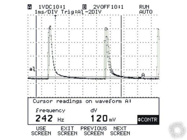
Went out & looked again on AC, and did see some activity, although it didn't appear to vary with the speed of the engine. Took out the scope & took a pix (below). When I press on the accelerometer, neither the pulse width nor the space between changes.
Last night I was looking at some other posts, and there was mention about a different tach line (I think it was a GREEN/ xxx wire somewhere near the hood release lever). Is this still valid, or was it for an earlier version of the truck? (I believe the post was for a 2007).
Thanks
------------- Tim
Posted By: tim051
Date Posted: August 07, 2013 at 1:59 PM
HA!
Sometimes even a blind squirrel finds a nut!
Found the tach line - it wasn't in the actual harness directly under the steering wheel, it was part of a group of wires that had heatshrink on them from the factory. (on the left hand side).
We're good to go now!
Thanks again for the help!!! ------------- Tim
Posted By: kreg357
Date Posted: August 07, 2013 at 6:44 PM
Good deal!  Enjoy the new toy. ------------- Soldering is fun!
Posted By: ponchantos3
Date Posted: April 14, 2014 at 7:57 AM
Hi Kreg,
It seems you are an installer. I have 2008 F350 Diesel, 5704 Viper and PKALL.
I've installed my previous alarms and now I'm working on my new truck and having issues
I'm getting the remote start error and the pkall is not programing
Now my remote start harness seems fine as I tested all the voltage coming through
TX and RX seems to be going to the correct, yel/orange and PURPLE / gray
ignition pink I connected to ignition 1 which is WHITE/ orange (same as where the remote start harness wire went to)
and as for ground I took straight to chassis.
Now is this all right?
tHANKS
-------------
DenKat
|