python 5706 door locks
Printed From: the12volt.com
Forum Name: Car Security and Convenience
Forum Discription: Car Alarms, Keyless Entries, Remote Starters, Immobilizer Bypasses, Sensors, Door Locks, Window Modules, Heated Mirrors, Heated Seats, etc.
URL: https://www.the12volt.com/installbay/forum_posts.asp?tid=136185
Printed Date: May 10, 2024 at 3:27 AM
Topic: python 5706 door locks
Posted By: hoe_nah808
Subject: python 5706 door locks
Date Posted: February 28, 2014 at 12:47 AM
2014 tacoma base model. wired in my alarm no problems. added dei 524f door locks. using only the green and blue off the actuators tho. wired them into some relays like this
87 fused 12v
85/86 to fused relay
87a ground
86 alarm lock ouput
85 alarm unlock output
30 to actuators
now when i stick my fuse in after i have everything wired up the actuators receive power immediately and either lock or unlock. i hit my remote unlock or lock and nothing happens. the actuators still have power, i pull the fuse out and i can hear the actuator lose power.
any help? not sure what im doing wrong.
Replies:
Posted By: blanx218
Date Posted: February 28, 2014 at 3:26 PM
Get rid of the ground on 87a
Posted By: freqsounds
Date Posted: February 28, 2014 at 7:07 PM
Those relays don't sound right at all.
For 5 pin relays:
Pin 85 - ground
Pin 86 - +12V
Pin 30 - Output
Pin 87a - Normally Closed Input
Pin 87 - Normally Open Input
What is the pinout on these actuators? I'll see if I can draft up a diagram for you. I just need to know which color does what on each actuator. The manual for the actuators should have this info.
-------------
No question is stupid or not worth asking. You were once a noob, right? :)
Posted By: hoe_nah808
Date Posted: February 28, 2014 at 7:24 PM
its a 5 wire actuator but im just using the blue and green. they have a brown, white, and black but those are for central locking.
also when i click the lock on my alarm one of the wires shows positive voltage not negative. then when i unlock the other wire shows the voltage.
i tried to use the relay wiring diagram on this site but it wasnt working.
Posted By: hoe_nah808
Date Posted: February 28, 2014 at 7:46 PM
https://www.the12volt.com/doorlocks/page3.asp#3wp
using this as a reference, if my alarm outputs are + then could i ground the (87)s instead of feeding them 12v?
Posted By: hoe_nah808
Date Posted: February 28, 2014 at 7:55 PM
https://www.the12volt.com/relays/relaydiagram49.html
tried this also didnt work
Posted By: freqsounds
Date Posted: February 28, 2014 at 8:03 PM
The relay diagram under "Actuators / Reverse Polarity" on that page is exactly what you need.
The 5706 puts out a (-) pulse, so this particular diagram is the exact one you should use.
The circuit would be completely different if you have (+) outputs.
-------------
No question is stupid or not worth asking. You were once a noob, right? :)
Posted By: freqsounds
Date Posted: February 28, 2014 at 8:04 PM
One more thing! Always make sure your (+) inputs are fused at the correct rating!
-------------
No question is stupid or not worth asking. You were once a noob, right? :)
Posted By: freqsounds
Date Posted: February 28, 2014 at 8:07 PM
Your second link is the one for (+) outputs. It won't work for this system.
-------------
No question is stupid or not worth asking. You were once a noob, right? :)
Posted By: hoe_nah808
Date Posted: March 01, 2014 at 3:51 AM
freqsounds wrote:
The relay diagram under "Actuators / Reverse Polarity" on that page is exactly what you need.
The 5706 puts out a (-) pulse, so this particular diagram is the exact one you should use.
The circuit would be completely different if you have (+) outputs.
so if I put a dmm to the wires coming off the harness what should it read when unlocking and locking?
Posted By: freqsounds
Date Posted: March 01, 2014 at 9:23 AM
With your red probe on a +12V constant source, and the black probe on the lock or unlock wire from the alarm, you should see it spike to 12V. The output duration of the pulse is usually .4 seconds by default.
After the relays are hooked up, both wires going to the actuator should be ground when not being sent a signal. When a lock or unlock signal is sent from the alarm, the relay should output a +12V pulse on one of the wires to the actuator.
Hope that makes sense!
-------------
No question is stupid or not worth asking. You were once a noob, right? :)
Posted By: hoe_nah808
Date Posted: March 01, 2014 at 2:07 PM
freqsounds wrote:
With your red probe on a +12V constant source, and the black probe on the lock or unlock wire from the alarm, you should see it spike to 12V. The output duration of the pulse is usually .4 seconds by default.
After the relays are hooked up, both wires going to the actuator should be ground when not being sent a signal. When a lock or unlock signal is sent from the alarm, the relay should output a +12V pulse on one of the wires to the actuator.
Hope that makes sense!
okay thanks that makes a lot of sense to me know haha..thanks for the help..going to try this out before i head off to work today
Posted By: hoe_nah808
Date Posted: March 01, 2014 at 3:01 PM
okay went out and found this.
using my dmm red wire on a constant 12v black wire to the alarm it will read 12v. when I click the lock/unlock button voltage drops.
on the relay
87 reads 12v
86/85 12v
86/85 going to the alarm reads 9v
30 reads 0.
when I lock/unlock from my remote pin 30 doesnt recieve any power at all. tried grounding 87a and still nothing on both of my relays.
Posted By: freqsounds
Date Posted: March 01, 2014 at 4:02 PM
85 and 86 are not the same terminals. They are the coil terminals. To make the relay trip, one needs ground and the other needs +12V. If they're both reading the same, disconnect the wires from the relay then meter. Pin 85 should have the ground feed from the alarm, and 86 should have the (+) constant feed with a diode connected from 85 to 86 with the band side on pin 86.
If your relays have diodes, this is probably why it's not working. The diagram at https://www.the12volt.com/doorlocks/page3.asp#arp has no diodes in the diagram. If both of your relays have diodes, switch 85 and 86 on relay 1.
You're using the blue and green wires from the alarm, right? The ones on the 3 pin connector?
It may be easier at this point to tear down the relays and use the diagram in the link above. Pay special attention to what I said about relay 1.
-------------
No question is stupid or not worth asking. You were once a noob, right? :)
Posted By: hoe_nah808
Date Posted: March 01, 2014 at 4:14 PM
yup green and blue from the alarm. gonna spend my day at work trying to figure out this relay situation.
Posted By: hoe_nah808
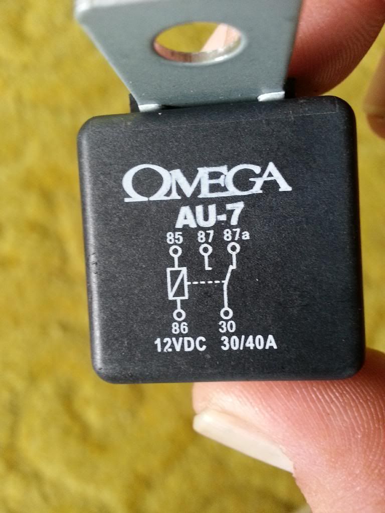
Date Posted: March 01, 2014 at 4:19 PM
Posted By: freqsounds
Date Posted: March 01, 2014 at 4:23 PM
Yea, there's a diode built in. That's what that zigzag line is across 85 and 86.
-------------
No question is stupid or not worth asking. You were once a noob, right? :)
Posted By: freqsounds
Date Posted: March 01, 2014 at 4:24 PM
Correction:that's a resistor. Not a diode.
-------------
No question is stupid or not worth asking. You were once a noob, right? :)
Posted By: freqsounds
Date Posted: March 01, 2014 at 4:32 PM
So this has a similar effect of a diode without the unidirectional effect of the voltage.
Try this: take just the (-) trigger and put it on pin 85. Connect 86 to +12V and leave the other terminals connected. Press the lock or unlock button and listen for a click from the relay. If it doesn't click, you'll probably need different relays.
-------------
No question is stupid or not worth asking. You were once a noob, right? :)
Posted By: hoe_nah808
Date Posted: March 03, 2014 at 5:17 PM
okay the relays work thats for sure. I put 12v to the 85 and grounded the 86 via chassis ground and the relay clicks. BUT im still not getting anywhere
85 constant 12v
86 ground from alarm GREEN/ blue harness
when I get my multimeter and put the red wire to the 86 pin and black wire to chassis ground I get a reading of 9volts. when I hit my lock button it jumps to 10volts. when I hit unlock itll drop to 7v.
doing this the relay DOES NOT click on or off. all the other wires are not connected
87 pin 12v
87a ground
with my dmm and the 85/86 pins hooked up the 30 pin turns into a ground on both of my relays. when I click the lock or unlock on my remote for my alarm nothing happens no jump/spike in pin 30. when I remove 87a from being grounded, nothing happens to the 30pin. its not a ground and no jump#spike in voltage.
these are all new relays...not sure where to go from here
Posted By: harryharris
Date Posted: March 03, 2014 at 5:27 PM
ER anyone thought to connect 87a on your relays to ground?
85 lock or unlock outputs
86 and 87 12V+ constant fused at 25 amps for 4 locks, 15 for two.
30s are lock outputs
87a ground
freqsounds I was going to pull you up on the diode answer but you were too fast.  ------------- Test before boxing up.
Posted By: freqsounds
Date Posted: March 03, 2014 at 5:27 PM
I'm not sure these relays are going to work. It seems that resistor is making things difficult. I would recommend trying relays that do not have a resistor. While you're at it, pick up some diodes (1N4004) too. These will be used for spike suppression.
-------------
No question is stupid or not worth asking. You were once a noob, right? :)
Posted By: hoe_nah808
Date Posted: March 03, 2014 at 8:17 PM
I have one relay without the resistor emblem on it that I bought today and that one isnt working either.
from the main harness of the alarm what needs to be plugged in for the door locks pin to work? just the main 12v and chassis ground right?
Posted By: freqsounds
Date Posted: March 03, 2014 at 8:28 PM
Yea, pin 85 should be ground, and +12V on pin 86. You can test one of these relays on a car battery. If it clicks, it should be working.
Remember, pin 30 is your output (i.e. to your actuator) and pin 87 is your input (i.e. your +12V constant that you want to send to your actuator).
But I think there might be an issue because your relays for the switches are sending ground on both legs of the actuators.
Try to unplug those relays before trying your alarm relay set. If it works, we've found the problem!
-------------
No question is stupid or not worth asking. You were once a noob, right? :)
Posted By: hoe_nah808
Date Posted: March 03, 2014 at 8:40 PM
okay so start from the beginng cause this is weird. the door pin on my alarm if I take my meter and put the black wire to any part of the alarm blue or green and I take my red wire to a 12v it reads on my meter 12v. same as if I took the meter to the chassis ground and a hot 12v.
when I put the 12v to pin 85 pin 86 reads 12v also.when I put a chassis ground to 86 the relay clicks. BUT when I put my alarm blue or green which technically is a ground the relay doesnt click. is that how its supposed to be? sorry ive been reading a lot and im really a newb woth relays
Posted By: smokeman1
Date Posted: March 03, 2014 at 9:35 PM
harryharris has laid out the answer for you. I just did his wiring on a bench setup I have and it works perfectly.
Go to the downloads section of this site. Search for Viper 5701. Download the install manual for the older style. On page 38 is a diagram for aftermarket actuators. Two relays needed or a DEI 451M.
Piece of cake.  ------------- When all else fails, Read the Instructions
Support the12volt.com Make a Donation
Posted By: hoe_nah808
Date Posted: March 03, 2014 at 9:50 PM
gonna return my relays. bought some online from a car audio website maybe they are different after all??
where do you guys get your relays from? man these things arent cheap. the ones i just got online are a lot cheaper than the ones i buy from napa n checkers
Posted By: hoe_nah808
Date Posted: March 06, 2014 at 7:42 PM
got this in the mail today...hopefully they work
Posted By: freqsounds
Date Posted: March 06, 2014 at 10:20 PM
Those should do it, don't forget to wire a diode from 85 to 86 on that one. White stripe toward 86.
-------------
No question is stupid or not worth asking. You were once a noob, right? :)
Posted By: hoe_nah808
Date Posted: March 07, 2014 at 5:45 PM
freqsounds wrote:
Those should do it, don't forget to wire a diode from 85 to 86 on that one. White stripe toward 86.
what do you mean by 85 to 86? how would u do that?
Posted By: freqsounds
Date Posted: March 07, 2014 at 7:54 PM
Connect the diode - the side without the strip to 85. The other end to 86. 85 and 86 are pins on the relay.
-------------
No question is stupid or not worth asking. You were once a noob, right? :)
Posted By: smokeman1
Date Posted: March 07, 2014 at 8:36 PM
Link to a pictorial that includes adding a diode to a relay.
Posted by kreg357.
https://www.the12volt.com/installbay/forum_posts.asp?tid=133810&KW=quenching+diode+on+relay
-------------
When all else fails, Read the Instructions
Support the12volt.com Make a Donation
Posted By: hoe_nah808
Date Posted: March 07, 2014 at 11:32 PM
smokeman1 wrote:
Link to a pictorial that includes adding a diode to a relay.
Posted by kreg357.
https://www.the12volt.com/installbay/forum_posts.asp?tid=133810&KW=quenching+diode+on+relay
thanks needed that pic...also I need one for both relays or just one?
Posted By: freqsounds
Date Posted: March 08, 2014 at 12:04 AM
Both relays should have a diode since they are connected to the alarm.
-------------
No question is stupid or not worth asking. You were once a noob, right? :)
Posted By: hoe_nah808
Date Posted: March 09, 2014 at 4:52 PM
im officially frustrated. I plugged in everything correctly and the relays still dont click on/off
I have 12v going to pin 86, when I check pin 85 on the relay with my dmm I get a 12v reading.
when I plug in my wire from the alarm harness to pin 85 it then reads 9v.
when I click the remote unlock/lock depending on which wire green or blue the pin 85 will jump up to10v. but it will NEVER get a ground signal.
no ground means the relay wont function correct? this is where im at so far..
any other suggestions?
Posted By: smokeman1
Date Posted: March 09, 2014 at 5:01 PM
Take the relay out. Attach a wire to the 86 pin, attach a different wire to the 85 pin. Put the wire for the 86 on the POSITIVE side of a 12 volt source, (ie, the battery). Then touch the wire from the 85 pin to the ground, (NEG battery). The relay should click, and the click again when the wire to ground is removed. Relay works?!
What are all of your wire connections to the relay?
-------------
When all else fails, Read the Instructions
Support the12volt.com Make a Donation
Posted By: harryharris
Date Posted: March 09, 2014 at 6:09 PM
Oh smokeman I thought you were going to quote that famous Idiot post which ends with "but it's surely only 12 volts?"
That apart x 2.
Relays are manufactured to work about 16 million times, ever seen a faulty one?
I'm 67 and in 40 odd years in this business I've seen 2 both Bosch fuel pump primer relays, on a Ford and a Porsche.
Could the OP please list complete wiring to the relays?
-------------
Test before boxing up.
Posted By: hoe_nah808
Date Posted: March 09, 2014 at 6:42 PM
the relay works when I put a constant 12v to 86 and a chassis ground on 85. it will click
87 - 12v
86 - 12v
85 - blue/green to alarm
30 - to actuators
87a I tried grounding it and not grounding, still nothing
Posted By: harryharris
Date Posted: March 09, 2014 at 6:47 PM
2 relays not one.
Lock relay:-
87 and 86 12V+ constant fused at 15 amps per 2 actuators.
87a ground
85 green from 5706
Diode 1N4004 across relay coil, 85 and 86, band to 86.
Unlock as above, except blue from 5706 to 85.
-------------
Test before boxing up.
Posted By: hoe_nah808
Date Posted: March 09, 2014 at 6:53 PM
yes im using 2 relays with diodes.
Posted By: harryharris
Date Posted: March 09, 2014 at 6:58 PM
Just test the blue and green lock outputs at the 5706 forget a DMM, it's much easier to use a 12 Volt test light e.g. Snap-On CT4F*.
Bet you originally didn't use diodes or tried wiring those wires to the actuators and you've fied the circuits.
*The best and fastest test going...when you know what you're doing.
In truth very few experienced old school installers will use DMMs.
-------------
Test before boxing up.
Posted By: harryharris
Date Posted: March 09, 2014 at 6:59 PM
In fact the only times I will ever use one are tach testing and continuity or to test suspect CAN wiring where I'm looking for 1-3 volts rather than 12 but there a scope is even better.
-------------
Test before boxing up.
Posted By: smokeman1
Date Posted: March 09, 2014 at 7:02 PM
The 30 pin should go to ONE of the colors of the actuators. 30 pin to the blue of the actuator. The other relay 30 pin to the green of the actuator.
In other words, tie both of the blue actuators wires to one of the relays 30 pin. Tie both of the green actuators to the other relay 30 pin.
The 85 pin is from the Python unit. Green to one of the relays. Blue to the other 85 pin.
-------------
When all else fails, Read the Instructions
Support the12volt.com Make a Donation
Posted By: smokeman1
Date Posted: March 09, 2014 at 7:15 PM
1st relay:
pin 86 and 87 to 12 volts
pin 87 to ground (chassis)
pin 85 to green wire from python unit (lock?)
pin 30 to green wire of both actuators
2nd relay:
pin 86 and 87 to 12 volts
pin 87 to ground (chassis)
Pin 85 to blue wire from python unit (unlock)
pin 30 to blue wire of both actuators
If they lock when they should unlock, swap the green and blue wires
-------------
When all else fails, Read the Instructions
Support the12volt.com Make a Donation
Posted By: harryharris
Date Posted: March 09, 2014 at 7:19 PM
X2 either blue or green at either 30 or 85.
-------------
Test before boxing up.
Posted By: the12volt
Date Posted: March 09, 2014 at 7:48 PM
smokeman1 wrote:
...
If they lock when they should unlock, swap the green and blue wires
I can see where this statement might be confusing to some, so just to clarify, if they lock when they should unlock, swap the green and blue actuator wires on terminal 30 of each relay OR swap the green and blue Python wires on terminal 85 of each relay, but not both sets of green and blue wies. -------------  the12volt Support the12volt.com the12volt Support the12volt.com
Posted By: smokeman1
Date Posted: March 09, 2014 at 8:00 PM
Yes indeed. I should have clarified that last line.
-------------
When all else fails, Read the Instructions
Support the12volt.com Make a Donation
Posted By: freqsounds
Date Posted: March 09, 2014 at 8:01 PM
The ground from the switches are interfering. The ground needs to be cut first.
-------------
No question is stupid or not worth asking. You were once a noob, right? :)
Posted By: freqsounds
Date Posted: March 09, 2014 at 9:18 PM
Sorry for the short reply, I had my hands full and my phone was acting like it was going to explode!
Your relays are probably correct. Let me explain what I mean.
You have the door switches, which are putting out a ground signal to the actuators at all times to both leads.
When your alarm relays are activated, they are sending that 12V from 87 to a wire that's grounded -- your actuator wire.
So we need to interrupt the ground on one of the leads going to the actuator. I'm going to reply again with a diagram to show what I mean.
-------------
No question is stupid or not worth asking. You were once a noob, right? :)
Posted By: freqsounds
Date Posted: March 09, 2014 at 9:30 PM
Wait, you do have door switches for these right? Or am I mixing this up with another thread? :)
-------------
No question is stupid or not worth asking. You were once a noob, right? :)
Posted By: hoe_nah808
Date Posted: March 09, 2014 at 9:53 PM
no door switches
Posted By: freqsounds
Date Posted: March 09, 2014 at 10:23 PM
My apologies! It's been a long night.
Are you seeing ground from the outputs on the 5706? Just to explain harryharris's test if you don't have a test light -- if you disconnect the blue and green wires from the relays (the outputs of the 5706), attach the black lead from the DMM to the blue wire, attach the red lead from the DMM to +12V and hit LOCK. You should see a spike in voltage on your DMM. The green wire is your unlock; try the same test with this wire. If you're not seeing this, there's something wrong with the 5706.
-------------
No question is stupid or not worth asking. You were once a noob, right? :)
Posted By: hoe_nah808
Date Posted: March 09, 2014 at 10:42 PM
I'll try again but I think I did try this once before and my voltage would drop a bit
Posted By: freqsounds
Date Posted: March 09, 2014 at 10:50 PM
You shouldn't be seeing any voltage on these wires at rest (i.e. when no lock/unlock commands are sent to the unit). And to clarify, you want to make sure the wires aren't connected to anything except the DMM at the time of testing.
-------------
No question is stupid or not worth asking. You were once a noob, right? :)
Posted By: harryharris
Date Posted: March 10, 2014 at 3:17 AM
Sorry to clarify no switches for the locks, right?
-------------
Test before boxing up.
Posted By: hoe_nah808
Date Posted: March 10, 2014 at 6:01 AM
so with my dmm black to 5706 unit and red to 12v my meter should read zero???
cuz I get a reading of 12v. and when I hit lock/unlock the voltage drops
no switches
Posted By: smokeman1
Date Posted: March 10, 2014 at 6:32 AM
A correction pointed out to me by freqsounds:
The 2nd line for each relay should be 87A to ground (chassis)
New layout below. My apologies for any confusion.
1st relay:
pin 86 and 87 to 12 volts
PIN 87 A to ground (chassis)
pin 85 to green wire from python unit (lock?)
pin 30 to green wire of both actuators
2nd relay:
pin 86 and 87 to 12 volts
PIN 87 A to ground (chassis)
Pin 85 to blue wire from python unit (unlock)
pin 30 to blue wire of both actuators
-------------
When all else fails, Read the Instructions
Support the12volt.com Make a Donation
Posted By: freqsounds
Date Posted: March 10, 2014 at 7:11 AM
That's correct. You shouldn't see any voltage without hitting lock or unlock.
-------------
No question is stupid or not worth asking. You were once a noob, right? :)
Posted By: hoe_nah808
Date Posted: March 10, 2014 at 2:19 PM
freqsounds wrote:
That's correct. You shouldn't see any voltage without hitting lock or unlock.
im definitely getting 12v. does this mean the 5706 is faulty?
Posted By: smokeman1
Date Posted: March 10, 2014 at 6:49 PM
Have you connected the relays as discribed above?
-------------
When all else fails, Read the Instructions
Support the12volt.com Make a Donation
Posted By: hoe_nah808
Date Posted: March 10, 2014 at 9:47 PM
smokeman1 wrote:
Have you connected the relays as discribed above?
yes numerous times with no results
Posted By: smokeman1
Date Posted: March 11, 2014 at 8:09 PM
All right, let's try this.
Take the blue and green leads from the actuators and attach one of the leads to a ground. Take the other lead and BREIFLY apply 12 volts to it. Does the actuator move? Lock or unlock? Yes? No?
Now switch the leads and see if the actuator moves in the other direction.
Remember BREIFLY apply the 12 volts. You are only trying to see if the actuators are working/moving.
If they work then connect your relays:
87 and 86 of both relays to 12 volts
87A of both relays to ground
the 30 pin of one relay to the green actuator lead and the 30 pin of the other relay to the blue actuator lead.
This should leave the 85 pin of both relays unconnected.
Take ONE of the 85 pin wire and touch/release it to ground.
Does the actuator lock or unlock?
Now do the same thing,(touch/release),with the OTHER 85 pin wire.
Does the actuator lock or unlock?
-------------
When all else fails, Read the Instructions
Support the12volt.com Make a Donation
|

