2015 subaru wrx cvt remote start ca6553
Printed From: the12volt.com
Forum Name: Car Security and Convenience
Forum Discription: Car Alarms, Keyless Entries, Remote Starters, Immobilizer Bypasses, Sensors, Door Locks, Window Modules, Heated Mirrors, Heated Seats, etc.
URL: https://www.the12volt.com/installbay/forum_posts.asp?tid=137045
Printed Date: April 29, 2024 at 4:05 AM
Topic: 2015 subaru wrx cvt remote start ca6553
Posted By: hvt8080
Subject: 2015 subaru wrx cvt remote start ca6553
Date Posted: August 03, 2014 at 11:38 AM
Hello everyone!
I attempting to install code alarm CA6553 requires two FLCANs.
1. Anyone with info on 2015 WRX automatic wiring please help.
I understand that this vehicle needs two FLCAN(one for immobil,one for door locks). I'll connect first FLCAN(program for immobilizer) as D2D to CA6553 and the second FLCAN(program for doors) as "hardwire."
According to immobilizer diagram, it doesn't show that the remote starter is requiring 12V
https://cdncontent2.idatalink.com/corporate/Content/Manuals/TB-SUB/FLC-AL(TB)-SUB-EN_20140604.pdf
https://cdncontent2.idatalink.com/corporate/Content/Manuals/DL-SUB/FLC-AL(DL)-SUB-EN_20140620.pdf
2. Do I need to connect 12V from vehicle to remote starter?
2b. both FLCANs needs to tap into 12V also?
According to the diagram the standard wires from remote starter are
IGN,ACC, and Start.
3. are there more than just those three standard wires?
4. Do I need to connect tach wire from vehicle to remote starter?
any help is greatly appreciated, thank you in advanced.
Replies:
Posted By: kreg357
Date Posted: August 03, 2014 at 4:27 PM
Ready Remote has the wiring info on your 2015 WRX. Here is a link :
https://www.readyremote.com/main.asp?make=Subaru&model=WRX
The FLCAN install diagrams do not show all the necessary R/S connections, only those applicable to the bypass
modules needs. As such, you will follow the Type 3 Install diagrams for both the transponder bypass module and
the DL module. As noted on the TB FLCAN diagram, standard ignition connections are still required. Use the Ready
Remote wire listing as your guide. Your car does have two Ignition circuits and two Starter circuits. Those should
be isolated and powered separately. Not familiar with your CA6553 R/S but I would assume an external relay will be
required.
The TB FLCAN that is going D2D with the CA6553 will get it's power & ground from the D2D harness. The W2W
DL FLCAN will need +12V, ground and GWR hardwired on it's 4 Pin connector. Remember to set the "Install Type" properly
on the two FLCAN modules after the F/W flash and prior to programming to the car.
The DL FLCAN will supply the Tach signal in W2W mode if properly connected to the CA6553's Tach Input wire.
Running in Tach mode usually provides the best engine start reliability.
In reviewing the CA6553 Install Guide, it looks like you can program the thick Pink/White IGN2 wire as Starter2.
Program Bank 4, Item 10 to Opt 3. Use this wire for the WRX White (+) wire @ ignition switch, white 8 pin plug, pin 7.
Then program the 4 Pin Alt Output BLACK / YELLOW wire as IGN2. Connect that wire to control an external relay for the
car's IGN2 circuit. Here is the wiring using the BLACK / YELLOW output wire :
Relay Pin 85 to CA6553 BLACK / YELLOW on 4 Pin ALT harness ( program Bank 5, Item 4 to Opt 3 )
Relay Pins 86 and 87 to +12V constant through 20 Amp fuse
Relay Pin 30 to WRX Blue (+) @ ignition switch, white 8 pin plug, pin 6
Relay Pin 87a not used - insulate ------------- Soldering is fun!
Posted By: hvt8080
Date Posted: August 08, 2014 at 2:24 PM
thank you for your quick reply Kreg357!
I'll attempt the install this weekend.
1. How many relays do I need?
2. Type of relay?model?
3. please explain what benefit of having the relay on IGN2 circuit.
Posted By: kreg357
Date Posted: August 08, 2014 at 6:26 PM
Just one relay for the extra ignition circuit. The most readily available relay is a Bosch automotive 30/40 Amp SPDT
relay. They can be found at better auto supply stores and possibly RadioShack. You can even get a SPST type being
as you don't need Pin 87a. Getting the relay 5 Pin harness will make things easier.
RadioShack appears to only keep the SPST style in store stock.
https://www.radioshack.com/product/index.jsp?productid=3020762&filterName=Type&filterValue=SPST
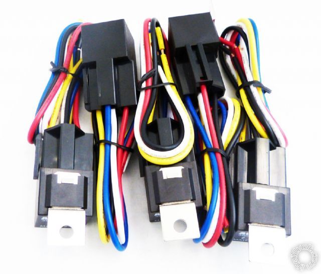
Here is a photo of SPDT relays and the harness :
The reason for using the external relay for IGN2 and the CA6553 for Starter2 has to do with the CA6553 programming
option limitations. You can't program the BLACK / YELLOW output wire to Starter2, only IGN2 and ACC2. You can program
the thick Pink/White IGN2 wire as Starter2. Just trying to make things easier for you. All ignition circuits should be
powered and isolated. ( Again, CodeAlarm is not my brand, but that is the way I'm interpreting the manual...) ------------- Soldering is fun!
Posted By: howie ll
Date Posted: August 09, 2014 at 4:28 PM
Simple rule, what tests out as a second starter may not be a starter wire at all. It may be a cold start enrichment device, a fuel pump primer etc. Joining the two lead to all sorts of engine management problems, DTCs and $$$ out of your pocket, hence separate isolated circuit via relays.
That unit is pretty basic, they sent me one here in the UK some months ago, it works well as an entry level Viper 5704/6.
-------------
Amateurs assume, don't test and have problems; pros test first. I am not a free install service.
Read the installation manual, do a search here or online for your vehicle wiring before posting.
Posted By: hvt8080
Date Posted: September 05, 2014 at 7:57 PM
Ok I will definitely make time tomorrow to do this, been so busy.
some questions I have:
1. Looking at the transponder bypass PDF, the 'IGNITION(+)OUTPUT'
where is this wire on the r/s?(I only see pink IGNITION1(+) and Pink/white IGNITION2(+)).
2. looking at the Doorlock PDF, it shows the same 'IGNITION(+)OUTPUT',
does this wire connects to BOTH FLCANs and then to what wire is 'VEHICLE IGNITION?'
3. when you say 'program bank 4, item 10 opt 3,' option 3 are you referring to the third column under '3 LED flash?'
4. 'Running in Tach mode usually provides the best engine start reliability' Looking at same program bank 4 item 4, seems like its defaulted to tach mode?
5. from the r/s PURPLE is STARTER OUTPUT - MOTOR SIDE(+), where do I connect this wire?
6. if I am using BLACK / YELLOW as IGN2, I'm guess I do not need the 'PULSE DURING CRANK' feature?
7. where is the best area to mount this r/s?
8. where do I mount the shock sensor?
thank you again for clearing up with the relay, the r/s did come with a relay.
|