Python 5303, 2001 Dodge Intrepid
Printed From: the12volt.com
Forum Name: Car Security and Convenience
Forum Discription: Car Alarms, Keyless Entries, Remote Starters, Immobilizer Bypasses, Sensors, Door Locks, Window Modules, Heated Mirrors, Heated Seats, etc.
URL: https://www.the12volt.com/installbay/forum_posts.asp?tid=137803
Printed Date: May 06, 2024 at 3:54 AM
Topic: Python 5303, 2001 Dodge Intrepid
Posted By: sportsfreaked
Subject: Python 5303, 2001 Dodge Intrepid
Date Posted: November 26, 2014 at 12:48 PM
Hello again; I am a newbie and started a new post now that I have decided on a unit. I do have a few questions to make sure I get everything I need for the install.
I have decided to go with the Viper 5303P. I am installing it on a 2001 Dodge Intrepid with out the skim (I have the black key). From what I understand I will need the following:
1 DEI 451M door lock kit. It's my understanding that this comes with resistors BUT does it have the ones I need a 600 ohm and 2700 ohm resistor? Should I buy a 600 ohm resistor and a 2700 ohm resistor?
I am going to use the + wire for the parking lights so I can eliminate a relay.
Is there anything else I need in order to install this unit? Any tips or tricks that I should know about?
Thanks for your time and input it is greatly appreciated! Have a blessed and wonderful holiday season!
ED
-------------
As always thanks for the information and help! It's greatly appreciated
Replies:
Posted By: kreg357
Date Posted: November 26, 2014 at 5:52 PM
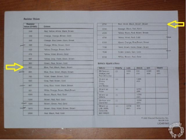
It's actually a 620 ohm resistor for Unlock, but yes, the 451M lit includes both of the needed resistors.
Here is a photo of the listed resistor values included in the 451M kit :
------------- Soldering is fun!
Posted By: sportsfreaked
Date Posted: November 26, 2014 at 7:04 PM
Kreg Thanks again for the information. I'm excited to do this project. Hopefully next weekend I can get it done. It should arrive nest Tuesday or Wednesday.
-------------
As always thanks for the information and help! It's greatly appreciated
Posted By: sportsfreaked
Date Posted: November 28, 2014 at 10:24 AM
Ok so I do have a question in regards to the door locks. I understand it's a single wire door lock/unlock. With the DEI 451m is it best to tap the single wire twice and then run a wire to the resistor then the other end of the resistor to the 451m wire for unlock and then do the same thing for lock? As always thanks in advance for the knowledge.
Also if I find the wire for + parking lights @kick panel I can just wire directly to that for the parking lights.
-------------
As always thanks for the information and help! It's greatly appreciated
Posted By: kreg357
Date Posted: November 28, 2014 at 11:59 AM
For the locks with the DEI 451M, just follow the Type H diagram. You can insert the appropriate resistor anywhere in the GREEN/ Black
and Blue/Black output wires. You can also combine them into one wire ( after the added resistors ) and then run just one wire to the
vehicles "one-wire" lock wire.
As for the (+) Parking Lights, just set the Pythons' jumper/fuse to (+) and connect the H1/11 White Parking Light wire to the correct wire in
the DKP. Parking Lights(+) BLACK / YELLOW (+) in driver kick panel
-------------
Soldering is fun!
Posted By: sportsfreaked
Date Posted: November 28, 2014 at 1:28 PM
Kreg once again thanks for the information. With being disabled and all the medication I am on I'm not as sharp as I once was. I like to think out loud and be prepared as I can be. Thanks again for your patience and time. I will let you know how the install goes.
Ed
-------------
As always thanks for the information and help! It's greatly appreciated
Posted By: sportsfreaked
Date Posted: November 28, 2014 at 1:31 PM
Sorry for the misinformation. It's a Python 5303P not a Viper. I said Viper above so sorry for the miscommunication.
-------------
As always thanks for the information and help! It's greatly appreciated
Posted By: sportsfreaked
Date Posted: November 30, 2014 at 10:00 AM
The other question that I have is for the parking lights. In researching this some say DO NOT use the + wire @ kick panel and only use - wire with relay. Others say you can use the + wire. I would like to use the + wire because that will eliminate a resistor and relay.
I'm looking for opinions on this. Again this unit is a Python 5303. Thanks. ED
-------------
As always thanks for the information and help! It's greatly appreciated
Posted By: kreg357
Date Posted: November 30, 2014 at 4:42 PM
I usually go with the (-) Parking Light wire and a 110 ohm resistor through a relay. I have these nice little +12V mini-relays
that are less that $.60 each ( in qty's of 50 ). That being said, you try a locate the (+) Parking Light wire in the DKP or with
this info below. Once you have located the wire & verified it with a DMM, you could take a fused jumper wire ( 5 Amp fuse )
and try it manually. If all is well, then connect the Python's Parking Light wire ( jumper set to + ).
Parking Lamp (+) BLACK / YELLOW (+) AT BODY CONTROL MODULE *
* Body Control Module (BCM) Located Behind Fuse Box. ------------- Soldering is fun!
Posted By: sportsfreaked
Date Posted: December 01, 2014 at 5:31 PM
Kreg your insight and patience and ability to help others is a true blessing! I can't express enough how much I appreciate your responses to what may seem dumb questions!
In my research to do this project it's my understanding that my car 2001 Intrepid has 2 ignition wires and also 2 accessory wires. Now I don't have the unit yet it should be here Thursday but will I need to run relays for the 2nd ignition and 2nd accessory wire?
I have tried to find a install manual for the Python 5303 but I do not see one on the site. Would an Avital 5303 be the same thing for the most part? As always thanks for the answers.
Ed
-------------
As always thanks for the information and help! It's greatly appreciated
Posted By: kreg357
Date Posted: December 01, 2014 at 6:01 PM
Good news and bad news. First the bad news - I don't use Python products so I am not sure if the Avital 5303 is the same.
Assuming they are similar ( DEI seems to follow the same color coding on most all of the wires ), here are the answers.
The 5303 can directly support the Interpid's one Starter wire, two Igniton wires and one of the Accessory wires. This is
shown below :
➤ Heavy gauge relay satellite wiring diagram
H/1 PURPLE STARTER OUTPUT TO STARTER (STARTER SIDE) Yellow (+) @ ignition harness \ cut wire
H/2 GREEN STARTER INPUT FROM IGNITION (KEY SIDE) Yellow (+) @ ignition harness /
H/3 RED (+) HIGH CURRENT 12V INPUT Pink/Black (+) @ ignition harness
H/4 ORANGE OUTPUT TO ACCESSORY CIRCUIT BLACK/ Orange (+) @ ignition harness
H/5 PINK OUTPUT TO PRIMARY IGNITION CIRCUIT Dark Blue/white (+) @ ignition harness
H/6 RED (+) (30A) HIGH CURRENT 12V INPUT Red (+) @ ignition harness
H/7 PINK/WHITE OUTPUT TO SECOND IGNITION CIRCUIT GREEN/ Red (+) @ ignition harness * Default is IGN2
H/8 RED / WHITE (+) (30A) HIGH CURRENT 12V INPUT Red (+) @ ignition harness
The second Accessory wire will require some extra parts. You will need a 30/40 Amp SPDT Bosch style automotive relay
and an in-line fuse holder with 20 Amp fuse. The wiring is shown below :
Relay Pin 85 to Python 5303 Remote start ribbon harness, Pin 4 ORANGE (-) 200mA ACCESSORY RELAY TURN ON
Relay Pins 86 & 87 to +12V constant through 20 Amp fuse ( Pink/Black (+) @ ignition harness )
Relay Pin 30 to Intrepid Second Accessory BLACK/ White (+) @ ignition harness
Relay Pin 97a not used
Looks like you will have to do some delicate surgery on the Remote start ribbon harness to make your nice, soldered,
connection to the Orange wire. ------------- Soldering is fun!
Posted By: sportsfreaked
Date Posted: December 01, 2014 at 7:03 PM
Kreg thanks for the info. Looks like I have plenty of relays For this project. You're full of good news lol. I will wait until I have the unit as I think I have everything I need for this. The wife will be happy for sure as it was pretty cold tonight.
I will probably wait until Saturday to start this as I have a procedure that I have to have done on Friday morning. If it goes OK I may be able to start Friday afternoon. I will do a write up of the project so that it may help someone else when I am done.
ED
-------------
As always thanks for the information and help! It's greatly appreciated
Posted By: kreg357
Date Posted: December 01, 2014 at 7:20 PM
Cool, a write-up with pictures on the Intrepid would be a welcome addition to the forum. Bulldog Security has some photo's of a few of the wires and trim removal : https://www.bulldogsecurity.com/bdnew/vehiclewiringdiagrams.aspx ( If you do take pictures, go with VGA mode. They are the right size for posting and have enough detail. )
Hope all goes well on Friday morning.  ------------- Soldering is fun!
Posted By: sportsfreaked
Date Posted: December 01, 2014 at 8:34 PM
I will probably use cannon digital camera to take the pics. Not sure how to get them to VGA but I will cross that bridge when I come to it LOL.
ED
-------------
As always thanks for the information and help! It's greatly appreciated
Posted By: sportsfreaked
Date Posted: December 02, 2014 at 6:30 PM
Well there was a delay in shipping the Python so it won't be here until next Wed 12/10. I will start on the project Thursday 12/11 and do a write up when I'm done. Hopefully I'll have pics as well.
-------------
As always thanks for the information and help! It's greatly appreciated
Posted By: sportsfreaked
Date Posted: December 02, 2014 at 7:17 PM
I do have one more question. I think this will be the last one I have but please don't hold me to it. It looks like I'm going to need like 4 relays. Can I power all 4 relays with one 12v fused wire since the relays will not all be in use at the same time? As always thanks for the time in answering.
Ed
-------------
As always thanks for the information and help! It's greatly appreciated
Posted By: kreg357
Date Posted: December 02, 2014 at 7:46 PM
Yes, but if you use a fuse rated at the highest relay's current draw, then it would not really protect the other circuits properly.
-------------
Soldering is fun!
Posted By: tedmond
Date Posted: December 02, 2014 at 9:06 PM
You should only need one additional relay for the second accessory circuit. everything else can be provided by the remote start unit.
-------------
Ted
2nd Year Tier 1 Medical School
Still installing as a hobby...pays for groceries
Compustar Expert
Posted By: sportsfreaked
Date Posted: December 03, 2014 at 1:38 PM
I need a relay for the trunk release, and don't I need a relay for the rear window defogger, and a starter kill switch and the parking lights?
-------------
As always thanks for the information and help! It's greatly appreciated
Posted By: tedmond
Date Posted: December 03, 2014 at 3:03 PM
in that case only 2 are required.
one for 2nd acc, one for trunk release. looking at the wiring guide there is a starter kill built into the satellite relay.
rear window defogger is negative so no need for a relay there. parking lights like i said you can adjust the polarity on the unit and connect accordingly.
-------------
Ted
2nd Year Tier 1 Medical School
Still installing as a hobby...pays for groceries
Compustar Expert
Posted By: sportsfreaked
Date Posted: December 06, 2014 at 2:47 PM
Ok Folks I have the unit and it has arrived. The only real questions I have is this. On the relay Satellite there is a 4 pin connector. it's labeled as such: Relay satellite Port
1. Blue.....(-)200mA Status output
2. Orange...(-)200mA Accessory relay turn on
3. Purple...(-)200mA Starter relay turn on
4. Pink.....(-)200mA Ignition relay turn on
The other question I have is the main harness:
H1/7 Blue.....(-)Instant trigger input zone 1 (What does this get hooked up to?)
H1/10 WHITE/ blue..... (-) Remote start activation input (What does this hook up to?)
H1/12 Orange..... (-)500mA ground when armed output (does this just go to ground?)
Once again I can't thank you all enough for your help and willingness to help others. It is GREATLY appreciated. Thanks
Ed
-------------
As always thanks for the information and help! It's greatly appreciated
Posted By: kreg357
Date Posted: December 06, 2014 at 3:01 PM
You will be using the Pin 2. Orange...(-)200mA Accessory relay turn on for the external relay that powers the ACC2 circuit in the car. Wiring was listed earlier. The other wires in that port won't be used.
H1/10 and H1/12 are not used for your application. Not sure on H1/7, the Avital 5303 install guide I'm using has it listed differently.
------------- Soldering is fun!
Posted By: sportsfreaked
Date Posted: December 07, 2014 at 5:47 PM
Ok so I lied. I have one last question that I can't seem to find the answer to. I currently have progressive locks on the Intrepid. If I wire the DEI 451m door kit for the lock and unlock with the proper resistors will it keep the progressive locks? On the unit I have a wire that say's it's for (-)200mA output for progressive locks in which the driver door unlocks first and the remaining locks unlock with the second press. Do I need to do additional wiring or will it keep the factory progressive locks? As always I GREATLY appreciate the input. Thanks.
ED
-------------
As always thanks for the information and help! It's greatly appreciated
Posted By: kreg357
Date Posted: December 07, 2014 at 6:11 PM
I can't remember, my my best guess is that you will loose the progressive unlock using the one-wire lock wire. If that
happens and it's really important to have progressive unlock, there is a way to do it with a relay and both unlock
wires from the Python. Second Unlock would go to the 451M and the primary unlock would go to a relay. The relay
would be connected to the unlock motor wire with the "5 wire" mode wiring. Here is the info on the drivers door unlock
motor wire : Unlock Motor Dark Blue @ BCM
------------- Soldering is fun!
Posted By: vane0804
Date Posted: December 08, 2014 at 12:06 AM
I just uploaded installation manual for Python 5303...look for it..
-------------
~It's me!
Posted By: sportsfreaked
Date Posted: December 08, 2014 at 6:01 PM
Ok I have a question please. It's going ok although I don't know how people do this for a living. I'm having issues finding the door trigger wire. One publication says it's brown and yet this site states yellow. I believe I'm correct in testing for it that it's a neg trigger. So I have my positive lead to constant power and neg lead on the suspected door trigger wire. With the door open it should read 12 volts and with the door closed 0 volts. Is this correct? Thanks as always.
-------------
As always thanks for the information and help! It's greatly appreciated
Posted By: kreg357
Date Posted: December 08, 2014 at 6:11 PM
That is the correct DMM set-up when for testing a (-) signal.
More info from ReadyRemote: Door Trigger Tan and Tan/Red (-) @ BCM ( plus diode isolation )
------------- Soldering is fun!
Posted By: sportsfreaked
Date Posted: December 09, 2014 at 4:44 PM
YEA Success!! I want to thank everyone for their help and patience with this newbie! I don't know how anyone does this for a living but I guess with experience they get faster and better. I will try to do a write up soon. I forgot to take any darn pictures:(. Thanks again to everyone and have a great Christmas and New year!
-------------
As always thanks for the information and help! It's greatly appreciated
Posted By: choperz
Date Posted: December 11, 2014 at 5:10 AM
Hello, I try to install a Pyhon 5303 in my toyota yaris 2007..
I bought th Xball2
I have read all your post, but I am no sure if I have to do the same in my car. can you give me any recomendation.
------------- choperz
Posted By: sportsfreaked
Date Posted: December 11, 2014 at 8:32 AM
Well I am not the one to really ask as I am a novice. My car did not have the skim system so I didn't need a by pass module for my car.
Have you looked on the site for a wiring guide for your car? That would be the place to start. I will say if you don't have a lot of experience in splicing and soldering and stripping wires I would not attempt it and I would have an expert install it.
I would search for wiring for your car and see if there is info out on the web for your car. Good luck.
-------------
As always thanks for the information and help! It's greatly appreciated
Posted By: sportsfreaked
Date Posted: December 11, 2014 at 8:34 AM
Check out this site https://www.yarisworld.com/forums/showthread.php?t=24860
-------------
As always thanks for the information and help! It's greatly appreciated
Posted By: sportsfreaked
Date Posted: December 11, 2014 at 8:37 AM
This is better to use it's here on the site https://www.the12volt.com/installbay/forum_posts.asp?tid=81694
-------------
As always thanks for the information and help! It's greatly appreciated
Posted By: kreg357
Date Posted: February 09, 2015 at 8:58 AM
As promised, here is a link to the install write-up with photo's, wiring and much detailed info on the 2001 Dodge Intrepid :
https://www.the12volt.com/installbay/file.asp?ID=1317 ------------- Soldering is fun!
|