4113 and dlpk on 08 impala
Printed From: the12volt.com
Forum Name: Car Security and Convenience
Forum Discription: Car Alarms, Keyless Entries, Remote Starters, Immobilizer Bypasses, Sensors, Door Locks, Window Modules, Heated Mirrors, Heated Seats, etc.
URL: https://www.the12volt.com/installbay/forum_posts.asp?tid=138002
Printed Date: May 12, 2026 at 9:40 AM
Topic: 4113 and dlpk on 08 impala
Posted By: chiefdone1
Subject: 4113 and dlpk on 08 impala
Date Posted: December 19, 2014 at 2:27 PM
Ready to install 4113 with one button remote with DLPK bypass and RFLCHGM on 08 Impala LT. Only want remote start. will use car fob for lock/unlock arm/disarm.
Here is what I believe the way I should wire it but not clear in several wiring areas.
On 4113;
HI connector only connections are on pin H1/8 to ground and H1/9 to light flash at BCM X2 pin 8 brn/wht.
H3 connector (Remote start harness)
H3/1 to toggle switch for ground
H3/3 brake shutdown to brake pedal wire
No other connections
Door Lock 3 pin connector
Pin 1 to BCM X7 pin 6 yel (unlock dr door)
Pin 3 to BCM X7 pin 7 lt grn (lock)
Heavy gauge relay 6 pin connector
Pin 1 and 3 to 12V on ignition switch wiring
Pin 4 output to blower control on Ignition switch brn
Pin 5 to starter circuit ppl wire
Pin 6 to primary ignition wire pink
Pin 2 NC
Satellite Harness 4 pin connector
No connections
On DLPK
12 pin connector
Orange NC
White /red trunk trigger NC
Violet/white tach NC will use virtual tach
Blue/white not sure does this need to go to H3/5 on 4113?
White violet gate open NC
Lt. Green Lock to Door lock conn on 4113 Pin 3.
Pink "accessory" does this go to Heavy gauge conn pin 4?
yellow "R code" to ignition switch white wire?
WHITE/ black to vehicle but where?
Grey hood trigger NC
Green trunk trigger NC
Violet/black heated seats NC
Blue unlock to BCM X7 pin 6
RED / white trunk/hatch NC
CAN data connector
Lt. green Data to transponder conn green wire?
Brown V ref. to ignition connector WHITE/ blk?
Not using D2D.
I have installed one previous RS but years ago in 98 Grand Prix.
Help appreciated.
-------------
Chiefdone
Replies:
Posted By: pentavolvo
Date Posted: December 19, 2014 at 4:54 PM
Do not hook up any lock wires as you aren't using them
Use the tach wire from dlpk it will work better then virtual tach
Posted By: chiefdone1
Date Posted: December 19, 2014 at 6:13 PM
Thanks for feedback.
Can u help on whether blue/white on DLPK has a connection to anything?
Also, any help on where blk/wht from DLPK connects at vehicle?
Appreciate your help.
-------------
Chiefdone
Posted By: kreg357
Date Posted: December 19, 2014 at 7:16 PM
The DLPK Blue/White wire does not connect to the Impala. It gos to the 4114 BLUE STATUS OUTPUT wire.
Don't see a BLACK/ White wire on the DLPK module. ------------- Soldering is fun!
Posted By: chiefdone1
Date Posted: December 19, 2014 at 7:55 PM
Thanks on the blue/white. Sorry, I meant WHITE/ black on the other question.
-------------
Chiefdone
Posted By: kreg357
Date Posted: December 19, 2014 at 9:03 PM
That goes to the transponder connector side of the cut Brown ACC wire. Here is a link to the DLPK install guide :
https://www.directechs.com/DocumentDownload.aspx?d=7314&p=122&f=1632
------------- Soldering is fun!
Posted By: chiefdone1
Date Posted: December 20, 2014 at 12:24 PM
Thanks. That helps.
-------------
Chiefdone
Posted By: chiefdone1
Date Posted: December 20, 2014 at 12:26 PM
Does the tach wire from 4113 also connect to a coil along with tach wire from DLPK?
Thanks
-------------
Chiefdone
Posted By: kreg357
Date Posted: December 20, 2014 at 12:44 PM
No, Sir. The DLPK generates a Tach from its' CAN SW connection to the Impala. The Tach output on the Violet/White
wire is strictly for use by the 4113 remote start unit and should not be connected to the Impala. The only connection is :
4113 H2/2 VIOLET/WHITE TACHOMETER INPUT WIRE to DLPK Violet/White Tach Output wire
If I not mistaken the Impala has "one-touch" starting. This is where a very quick turn and release of the key from ON to
START will start the engine ( the cars' computer takes over and cranks the starter motor the necessary amount of time
to get the engine running ). This being the case, you could set the 4113 Menu 2, Item 1 to Option 3 "OFF" and set Menu 2,
Item 4 to Option 3 and not connect any Tach wire to the 4113. ------------- Soldering is fun!
Posted By: chiefdone1
Date Posted: December 20, 2014 at 1:12 PM
Thanks for clarification and for suggestion on "one touch".
Your help is much appreciated. Will be installing Monday.
-------------
Chiefdone
Posted By: chiefdone1
Date Posted: December 21, 2014 at 12:21 PM
Can someone suggest where the antenna for the 4113 should be placed? The end piece has a sticky pad on it.
-------------
Chiefdone
Posted By: kreg357
Date Posted: December 21, 2014 at 12:28 PM
Center of windshield by rear view mirror works best.
-------------
Soldering is fun!
Posted By: chiefdone1
Date Posted: December 21, 2014 at 2:20 PM
Thanks again.
-------------
Chiefdone
Posted By: chiefdone1
Date Posted: December 22, 2014 at 10:13 AM
I am installing and expected to find ppl wire at ignition switch to connect ppl from 4113. It is not there. Is this connection needed? Or does comm thru CAN somehow make this unnecessary?
Thanks
-------------
Chiefdone
Posted By: kreg357
Date Posted: December 22, 2014 at 10:29 AM
You should not expect to find a Purple Starter wire in the ignition switch harness. The car does not have a traditional Starter wire.
The Purple Starter wire mentioned in the wire guides is under the hood, in the engine compartment, and used for "starter kill" purposes
only. The 4113's Purple (+) Starter Output wire is not used on your vehicle.
-------------
Soldering is fun!
Posted By: chiefdone1
Date Posted: December 22, 2014 at 10:42 AM
Thank you very much. This site is amazing.
-------------
Chiefdone
Posted By: chiefdone1
Date Posted: December 22, 2014 at 2:17 PM
On the heavy gauge relay wiring, the wires r like 10 ga. The wires I am supposed to connect to at ignition switch r 18 ga or so. Is this the right place to connect these heavy gauge wires?
-------------
Chiefdone
Posted By: kreg357
Date Posted: December 22, 2014 at 2:45 PM
A conditional YES. ( I am not there with my Digital Multi Meter checking and verifying each wire prior to making a nice solder connection.) Does it look like the picture posted earlier? Did you verify the wires with a DMM? It is very common for newer vehicles to have small gauge wires at the main ignition harness. Some wires on new Toyota's are like 26 gauge.
-------------
Soldering is fun!
Posted By: chiefdone1
Date Posted: December 22, 2014 at 2:53 PM
Yes and yes. Thanks
-------------
Chiefdone
Posted By: chiefdone1
Date Posted: December 22, 2014 at 3:23 PM
Ok. Brake switch says to look for 12 v when brake pedal pushed. What I see is 5 v. Does the H3 brown wire go on the light green at brake switch?
-------------
Chiefdone
Posted By: kreg357
Date Posted: December 22, 2014 at 3:30 PM
No. It should be +12V and a Light Blue wire. Here is the info from Bulldog Security :
| BRAKE |
LT. BLUE (+) |
IN DRIVER KICK or BCM, BROWN PLUG, PIN 5 | ------------- Soldering is fun!
Posted By: chiefdone1
Date Posted: December 22, 2014 at 9:06 PM
I completed installation but have problems.
One, when I plugged in DLPK CONN 1, I did not get the flash on the unit that it said I should while holding down button on unit.
Went ahead and connected the other plugs on DLPK and all plugs on 4113.
When I tried to remote start, lights came on, heard 4 clicks and then shut off with message on car to Service Theft Deterrent System. Tried sequence again and then it "freezes" until I remove ground on H3/1. Then the parking lights stay on until I open drivers door. Car still starts with key and all acts normal.
Left menu 1 as it came. Changed menu 2 feature 1 to off. Changed menu 2 feature 4 to 1 second. All others remain as it came.
I know I must have several issues but am thinking the theft deterrent message has something to do with the DLPK not flashing or programming correctly.
Where should I start? Read out diagnostics and got 7 flashes yet if I leave toggle off, it won't even try to star remotely. When I turn it on, it tries.
Thanks for any guidance.
-------------
Chiefdone
Posted By: kreg357
Date Posted: December 22, 2014 at 9:41 PM
Here is what your wiring should look like :
Avital 4113
H1/1 LIGHT GREEN/ BLACK FACTORY ALARM DISARM Not Used
H1/2 GREEN / WHITE FACTORY REARM Not Used
H1/3 YELLOW (+) IGNITION OUT (TO ALARM) Not Used
H1/4 WHITE/ BLUE (-) ACTIVATION INPUT Not Used
H1/5 ORANGE (-) GROUND WHEN LOCKED Not Used
H1/6 BROWN (-) HORN OUTPUT tan (-) @ BCM under driver dash, brown plug, pin 18
H1/7 RED / WHITE (-) TRUNK RELEASE OUTPUT Not Used
H1/8 BLACK GROUND Chassis Ground
H1/9 WHITE (+/-) LIGHT FLASH *** Set to (-) BROWN / white (-) @ BCM under driver dash, white plug, pin 8
H2/1 BLACK/ WHITE (-) NEUTRAL SAFETY SWITCH INPUT Chassis Ground
H2/2 VIOLET/WHITE TACHOMETER INPUT WIRE DLPK Violet/White
H2/3 BROWN (+) BRAKE SWITCH SHUTDOWN WIRE lt. blue (+) BCM under driver dash, brown plug, pin 5
H2/4 GRAY (-) HOOD PINSWITCH SHUTDOWN WIRE Hood Pin or DLPK Grey if Impala has Factory Hood Pin
H2/5 BLUE/WHITE (-) 200mA 2ND STATUS/REAR DEFOG Not Used
4-pin satellite harness diagram
1 BLUE STATUS OUTPUT DLPK Blue/White
2 ORANGE (-) ACCESSORY OUTPUT Not Used
3 PURPLE (-) STARTER OUTPUT Not Used
4 PINK (-) IGNITION OUTPUT Not Used
Heavy gauge relay wiring diagram
1 PINK (+) (30 AMP) OUTPUT TO IGNITION CIRCUIT Pink @ Ignition Plug
2 PURPLE (+) (30 AMP) OUTPUT TO STARTER CIRCUIT Not Used
3 ORANGE (+) (30 AMP) OUTPUT TO ACCESSORY CIRCUIT Brown @ Ignition Plug
4 RED (+) (30A) HIGH CURRENT 12 INPUT RED / white #1 @ BCM under driver dash, black plug, pin 1
5 PINK/WHITE (+) PROGRAMMABLE OUTPUT Not Used
6 RED (+) (30A) HIGH CURRENT 12V INPUT RED / white #2 @ BCM under driver dash, black plug, pin 2
Door lock harness, 3-pin connector
1 BLUE (-) UNLOCK OUTPUT DLPK Blue
2 EMPTY NOT USED
3 GREEN (-) LOCK OUTPUT Not Used
DLPK ( Follow diagram )
Violet/White to 4113 Violet/White Tach
Blue/White to 4113 Blue Status Output
Grey to 4113 H2/4 Grey ( if Impala equipped with hood pin )
Blue to 4113 Blue Unlock
Plus these 5 wires to Impala as per diagram
Yellow
WHITE/ Black
Pink
Light Green
Brown ------------- Soldering is fun!
Posted By: chiefdone1
Date Posted: December 23, 2014 at 11:32 AM
Rechecked all wiring as per your last post. The only thing I didn't hook up was hood trigger. As I understand it, this input is not active unless it sees a ground when hood opened. Other than the safety aspect of this, but does the input require to be hooked up?
Still will not remote start. Get message to "Service Theft Deterrent System".
Have never seen flash on DLPK to indicate it is active. Is it possibly bad? Any other thoughts?
I really appreciate all your input on this.
-------------
Chiefdone
Posted By: kreg357
Date Posted: December 23, 2014 at 12:15 PM
Did the DLPK program properly as per the install guide? ( page 2 of the install guide )
-------------
Soldering is fun!
Posted By: chiefdone1
Date Posted: December 23, 2014 at 12:55 PM
No, it did not. I tried several times but near saw the confirming flash on the DLPK.
-------------
Chiefdone
Posted By: kreg357
Date Posted: December 23, 2014 at 1:44 PM
Sounds like a bypass module issue. ------------- Soldering is fun!
Posted By: chiefdone1
Date Posted: December 23, 2014 at 4:22 PM
Thank you kreg357 for all your help. I believe you have helped me greatly but unfortunately, system doesn't work.
I have today ask for a replacement DLPK from my supplier. I explained all I had done and that I do believe the DLPK is the problem.
-------------
Chiefdone
Posted By: chiefdone1
Date Posted: December 23, 2014 at 7:56 PM
Maybe you can help me with this question. My supplier has agreed to exchange my DLPK. However, I have to return it before they will send a new one. Since I have wired everything (soldered and taped, when I remove the DLPK, will I have to splice any wires together to let the car run normally? I am thinking particularly of the brown wire a cut on the transponder.
Thanks
-------------
Chiefdone
Posted By: kreg357
Date Posted: December 23, 2014 at 8:49 PM
Will he let you keep the harnesses and just return the module? He could just send you a replacement module without the harnesses, they won't be of much value after they were cut & soldered. What a pain to remove all the harnesses. But yes, you must temporarily reconnect that cut brown wire. Think I would leave about an inch or two of DLPK wire at each connection and splice into that when the new one arrives. You could just strip and twist the two sides of the Brown wire connection and insulate with black tape until the replacement arrives to drive the car.
-------------
Soldering is fun!
Posted By: chiefdone1
Date Posted: December 24, 2014 at 6:29 AM
Yes, they will let me keep the wiring. (Very considerate and I appreciate that. I will just jumper between the pink and WHITE/ blk wire near the plug.
Thanks again!
-------------
Chiefdone
Posted By: chiefdone1
Date Posted: March 29, 2015 at 9:43 PM
I have installed the 4113 and DLPK with RFLGHGM loop on an 08 Impala LS.
First DLPK did not initialize (flash) when I first plugged it in per instructions. Sent it back and got a replacement. Installed it today and it too did not "flash" the LED on the DLPK when I installed it.
Went ahead and connected everything and checked programming. Car will start and run on "voltage" setting (menu 2 item 1). However, it still displays the message that Security System has a problem.
Does this tell me that the DLPK is still not initializing correctly? What else can I check.
Also, I have to key start the car first before the remote will start it once.
Thanks for any suggestions.
-------------
Chiefdone
Posted By: chiefdone1
Date Posted: March 30, 2015 at 12:07 PM
I have a new issue. In trying to work out issues, my 4113 is "stuck". The LED is flashing 1/sec and I can't clear it. Any suggestions?
-------------
Chiefdone
Posted By: kreg357
Date Posted: March 30, 2015 at 8:34 PM
Also, I have to key start the car first before the remote will start it once.
This indicates that the DLPK is not receiving constant +12V power input ( or possibly Chassis Ground ).
Here is a note from the install guide :
WARNING: Every time the DLPK is
disconnected, once reconnected the vehicle
needs to be started with the key.
Seems that both issues, bypass module programming and the needed key start prior to the one R/S, are related.
Please review and / or post your DLPK CN1 wiring. Personally, I would cut the far end of the CN1 harness and
hard wire the +12V and Chassis ground wires to the 4113 thick Red ( H2/4 or H2/6 and H1/8 Black wires ). Remember
that while the DLPK guide states the the +12V is Blue and the Chassis Ground is Black, these colors can vary, so go
by the actual pin location. ------------- Soldering is fun!
Posted By: chiefdone1
Date Posted: March 31, 2015 at 8:10 AM
My DLPK wiring on Cn1 is pin 1, blu, to large pink on 4113. Pin 2, blk, is to same wire as 4113 H1 pin 8.
As I posted later, my current problem is that the 4113 LED is flashing once per second and nothing I have tried will stop it. I have disconnected all plugs for 12 hours; tried the trouble shooting procedure; tried the programming procedure and nothing stops the 4113 LED from flashing. No response from valet button and nothing from remote.
I am stopped until I can "unfreeze" the 4113. What do I have to do to get the flashing LED to go off?
-------------
Chiefdone
Posted By: kreg357
Date Posted: March 31, 2015 at 11:53 AM
Not sure on the 4113 but the DLPK should not be getting its' constant +12 Volt power from the vehicles main Ignition wire. That is only ON when the key is in the ON position. It needs constant +12V all the time. Connect the DLPH CN1 Blue to a thick Red wire mentioned above.
-------------
Soldering is fun!
Posted By: chiefdone1
Date Posted: March 31, 2015 at 11:59 AM
Sorry, I meant large RED. So I am ok on that. I have verified that I have constant 12 v at 4113 and DLPK with a DVM.
I am still hung with the 4113 flashing LED.
-------------
Chiefdone
Posted By: chiefdone1
Date Posted: April 01, 2015 at 1:11 PM
Ok. I finally stopped flashing LED by manually starting and trying different sequences of buttons. It will start remotely one time. Second time, it says "check theft security system". New information is it will start remotely IF I leave key in ignition in off position. I can then take over by turning key to ON and pressing brake.
I do have 12 VDC at Cn 1 on DLPK. Have never yet seen flash on DLPK when powering it up per instructions. Therefore, I don't believe it is functioning and the RFLCHGM loop is not able to fool the system to think there is a key there.
This is second DLPK module and both act the same.
Any other suggestions?
Thanks
-------------
Chiefdone
Posted By: chiefdone1
Date Posted: April 01, 2015 at 8:03 PM
Latest update. I found on another blog that some of these had the power wire color incorrect for the DLPK. My paper said blue was 12v, in another book, it showed red was 12v so I tied the red to the 12v large red wires of the 4113 and then followed the instuctions. When I depressed the button and inserted Con 1, I got the LED on the DLPK!
NExt step was to start the car with the key and that would program the DLPK. Now the car will not start with the key.
LED is still lit on DLPK but since the car won't start, it never goes to flashing which would indicate it programmed. That is the only thing I changed. What should I try next? If I reconnect the brown wire from the transponder, it may start but may not program. That seems to be the next step and may mean I am close to solving this whole installation.
Thanks for any thoughts.
-------------
Chiefdone
Posted By: kreg357
Date Posted: April 01, 2015 at 8:51 PM
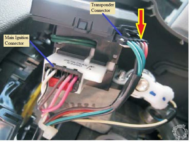
Well, I'm slightly confused. A few things to re-state.
There are two connectors at the ignition switch that are used in the install. One is the Main Ignition connector. The other is the
Transponder connector. This is shown in the photo on Page 1. While some of the wires in these connectors have the same name
and color, for the purposes of the install, you must follow the DLPK install guide very closely.
On the Main Ignition connector the Pink Ignition wire and the Brown Accessory wire are used. They will have connections from
the Avital 4113 thick wires. The DLPK Yellow wire will connect to the White V Data wire on this same plug.
On the Transponder connector, no 4113 direct connections are made. Only the wires shown in the DLPK install guide are connected
to this plug. Additionally the cut Brown ( or possibly Yellow ) wire and it's connections are important. the DLPK WHITE/ Black must go
to the connector side on this cut wire and the DLPK Pink wire must go to the car side of this cut wire.
As mentioned earlier :
Seems that both issues, bypass module programming and the needed key start prior to the one R/S, are related.
Please review and / or post your DLPK CN1 wiring. Personally, I would cut the far end of the CN1 harness and
hard wire the +12V and Chassis ground wires to the 4113 thick Red ( H2/4 or H2/6 and H1/8 Black wires ). Remember
that while the DLPK guide states the the +12V is Blue and the Chassis Ground is Black, these colors can vary, so go
by the actual pin location.
The DLPK is actually a Fortin CAN-SL2 module OEM'd to Xpresskit. Here is a link to the CAN-SL2 install guide :
https://fortin.ca/download/1179/can-sl2_chevrolet_impala_(2006-2009).rev-a.pdf
While there are wire color differences, the pin locations remain the same. So, go by the pin location ( not the wire color ) for the
CN1 wires.
I'm not sure exactly where the problem is but the wiring chart given on Page 3 should be accurate and the DLPK ( CAN-SL2 )
install guide should be followed exactly. ------------- Soldering is fun!
Posted By: tedmond
Date Posted: April 01, 2015 at 8:57 PM
The 4 pin data plug is where your power is. It's pin 1 either red or blue depending on the revision. are you using it in d2d mode?
i've used the fortin can-sl2 many times before (dlpk is a rebranded fortin) and the white 14pin plug can be plugged in backwards. If so the car will not start.
-------------
Ted
2nd Year Tier 1 Medical School
Still installing as a hobby...pays for groceries
Compustar Expert
|