2004 ford f150 lariat remote start 5706v
Printed From: the12volt.com
Forum Name: Car Security and Convenience
Forum Discription: Car Alarms, Keyless Entries, Remote Starters, Immobilizer Bypasses, Sensors, Door Locks, Window Modules, Heated Mirrors, Heated Seats, etc.
URL: https://www.the12volt.com/installbay/forum_posts.asp?tid=138062
Printed Date: April 27, 2024 at 1:59 AM
Topic: 2004 ford f150 lariat remote start 5706v
Posted By: willy1094
Subject: 2004 ford f150 lariat remote start 5706v
Date Posted: December 26, 2014 at 2:36 PM
Hello,
This is my first post to the forum. I found this forum during my research for a remote start for my truck. I've installed many stereos through the years in many different makes of vehicles but still apprehensive about the remote start. I originally intended to purchase and have it installed by BestBuy. After talking to the installers a few times I wasn't sure they were the best people to trust for this task. Since they were my only option locally I started looking into DIY installation and think I have found some really great information. I actually enjoy DIY projects even if they are challenging. I'm basically at the point were I want to be sure that I have all my information correct before proceeding.
I received the viper 5706V as a gift and plan on purchasing Xpresskit PKALL for the bypass module. This bypass has the D2D and should just plug into the viper system. I also have two factory keys for programming so that shouldn't be an issue. I also know I will need to get diodes for the door locks and a relay to use the courtesy light feature when I disarm the system (I may opt to just disregard the courtesy light because I cannot find any real wiring help for that).
I found the wiring info for my truck here:
https://www.bulldogsecurity.com/diagrams/diagram.asp?ModelID=18264&MakeID=18&link=Bulldog
I found what appears to be a nice install guide on this forum:
https://www.f150forum.com/f4/viper-5706v-alarm-keyless-remote-start-install-pics-256484/
I've also located the wiring guide pdf for the viper 5704v on this site
My question is, if I use the above information, should I be able to complete this install? Does anyone have any other tips they can provide? Also, I would like to activate my heated seats via to remote. I read somewhere that this would also require a relay but cannot find the site I read that on. Anyone have any pointers on that?
Thanks for any help!
Replies:
Posted By: st1nky
Date Posted: December 26, 2014 at 5:07 PM
hey bud,I am also new here but there is a relay section here that explains about relays https://www.the12volt.com/relays/relays.asp
Posted By: smokeman1
Date Posted: December 27, 2014 at 6:42 AM
Here is a link to a pictorial on my 2004 F150 Super Cab I did back in April.
https://www.the12volt.com/installbay/forum_posts.asp?tid=136387
-------------
When all else fails, Read the Instructions
Support the12volt.com Make a Donation
Posted By: willy1094
Date Posted: December 27, 2014 at 12:07 PM
Thanks st1nky. I have a very basic understanding of relays and have found the relay I'll need if I decide to hook up the courtesy light.
smokeman1, thank you for your link/post. That will help a lot. I think I'm going to go the route of installing next to my BCM since most of the wires are all right there together. It looks like the bypass you used is no longer available or it is marked under a different name.
I'd rather not have to leave a key in the truck so I'm looking at the PKALL. According the their website, I will not have to hook it up to anything to program it. The instructions I pulled off the web seem pretty vague and it does not look like there is a wire to wrap around the ignition barrel. Do these type bypassed not require that wire? The PKALL also utilizes the D2D connector that the Viper RS has so that was another reason I am leaning toward it. Please, any input on this bypass would be great. Another option is the XK04.
I would ultimately like to turn on my heated seats via AUX. I'm not sure how that circuit operates so I'm not sure what direction I should be looking in for that. It could be a simple as finding the correct wire to attach to but I thought I read a relay was needed. I could really use help with this area of the install.
Thanks again for any help
Posted By: willy1094
Date Posted: December 27, 2014 at 1:14 PM
Another question: What is the "door trigger in" for? I see the lock and unlock but then there is the door trigger in that has to be connected for all 4 doors. Is this just the door switch that indicates if the doors are closed?
Thanks again
Posted By: davep.
Date Posted: December 28, 2014 at 1:49 AM
In the mid-2000's F150 you can connect the blk/yel Domelight supervision directly to the Ford orn/grn at the rear of the light switch. No relays, no diodes. The orn/grn is the control for the Ford's dome light relay. Ground the orn/grn = domelights ON.
Posted By: davep.
Date Posted: December 28, 2014 at 2:06 AM
willy1094 wrote:
I would ultimately like to turn on my heated seats via AUX. I'm not sure how that circuit operates so I'm not sure what....
willy1094 wrote:
What is the "door trigger in" for?
I suggest you study the Install Guide, and find and study factory wiring diagrams for your truck until you are 100% confident in your understanding of how basic installs are executed, and you have a VERY good understanding of the terms and definitions used in the Install Guides. (DEI documentation is fussy and clunky, and prone to errors regarding pin-outs. Good Luck).
After you understand "Door Trigger" and which polarity to use, and how to diode-isolate the F150, or use the dome lights with appropriate programing to avoid "door-open chirps", you can move on to more advanced features such as heated seats.
We had a guy on here last week that fried his Ford's light switch because he messed up the light-flash connection. Ford requires special treatment. Cost him $100 for a new switch.
Best Buy wouldn't be my choice of installers either, but they probably are further up the learning curve than you appear to be at this point. Be very careful. You're at that classic point where you know just enough to get yourself into trouble and do some real damage to your truck.
Keep reading, keep learning. Burn up a BCM with a dumb mistake, and you'll be out several hundred bucks plus a visit to the Stealer for a $150 reprogram. That Best Buy Install would look like a bargain in comparison.
:02cents: Take it or leave it.
PS, Do It Yourselfer's such as yourself are why DEI doesn't honor a warranty unless it's installed through one of their dealers. There are too many ugh-knowns that can let the smoke out when installed by individuals that really shouldn't be doing it by themselves yet.
Posted By: willy1094
Date Posted: January 02, 2015 at 11:09 AM
I have studied the install guide, I purchased a complete service manual for my truck and am very comfortable making electrical connections. As far as execution, I have three different installation guides that are very detailed that I can follow. I've gone threw the install and understand all the aspects of their installation (other than the questions I posted here). I came to the forum in an attempt to find knowledgeable people that might assist with a few questions I might have in regards to DEI terminology as well as adapting this install to fit my needs. The ENTIRE reason I would not go to Best Buy is because they said heated seats could NOT be activated via remote despite me telling them that DEI/Viper says it can. There is also a youtube video showing it can be done. I know, from my service manual, that the heated seats are activated my a momentary negative signal. I could figure this out but thought someone would have some input to save some time.
I'm not just trying to save some money with this install. I WANT to do the install. I am an avid DIY'er in almost every aspect of my life. I am making every attempt to not just take a stab at and make sure I KNOW everything I need to know. How else am I going to do this without asking questions? DEI is not help withholding information. As you noted, their "install guide" if pretty vague and I doubt anyone could say that they don't do this on purpose. They can run their business as they see fit, but had I known their utter dis-contempt for end users it would have chosen a product from a company that offers more support. Again, this was a gift and am looking forward the installing it. If you can help, help. If you can't or don't want to, thanks any way.
I really am thankful to anyone that has helpful information. It does bother me when someone comes along and basically tells you to eat it. After all, forums of this nature thrive because people know information that other people need. I don't know electrical at an engineering level, but for an install, I don't need to.
Thanks again
Posted By: willy1094
Date Posted: January 02, 2015 at 11:11 AM
davep. wrote:
In the mid-2000's F150 you can connect the blk/yel Domelight supervision directly to the Ford orn/grn at the rear of the light switch. No relays, no diodes. The orn/grn is the control for the Ford's dome light relay. Ground the orn/grn = domelights ON.
This was very helpful! I will look into this as I've only ever heard that a relay was needed, but it makes sense.
Posted By: oldandtired
Date Posted: January 02, 2015 at 9:12 PM
Willy1004: I too have recently purchased a remote start for my ford F150 truck and eagerly awaiting its delivery. These forums are a great tool for resource as there are many skilled trades people and and avid DIY'ers. Please post your results with your install as I was curious as well regarding the dome light. Happy new year.
Posted By: willy1094
Date Posted: January 08, 2015 at 2:55 PM
Is there any down side to attaching the door sense to the dome light instead of at the BCM? Just seems easier than messing with isolating 4 wires. I will go the normal route if there is ANY reason connecting to the dome wire is not advisable.
Thanks
Posted By: kreg357
Date Posted: January 09, 2015 at 6:22 AM
Depending on the after-market alarm system, Dome light delay / fade can cause issues. Compustar units have this programming option :
3-03 Dome Light Delay This option is used when connecting the door trigger input to the vehicles dome light circuit. It
delays the door trigger input to prevent the door open icon displaying on 2 Way remotes upon
lock/arm.
Can't remember if the 2004 F150 has dome light delay and not sure about your Viper 5706v capabilities. ------------- Soldering is fun!
Posted By: tedmond
Date Posted: January 09, 2015 at 7:50 AM
The viper has the door chirp error off. It ignores the door pin for ~10 seconds I believe.
-------------
Ted
2nd Year Tier 1 Medical School
Still installing as a hobby...pays for groceries
Compustar Expert
Posted By: willy1094
Date Posted: January 09, 2015 at 11:51 AM
First, I want to thank everyone that has already helped with the questions I had up to this point. Ive searched countless forums and read anything I could find about installing the remote start in my truck. I feel like I am at a point where I can get this installed. I plan on mounting the remote start next to the BCM (behind the rear seat) since most connections can be made here and ease of access. I do still have a few questions where I either found conflicting information and/or feel like I could go another route.
My first area of concern is the (+) 12V connections. One person says they made the connections at the BCM. His connections where: 6-pin harness pin 1 (Red) to BCM (Tan/Wht), 10-pin harness pin 2 (RED / Blk) and pin 5 (Red) to BCM (Lt Grn/Yel). Another person made all three of these connections at the amplifier (+)12V constant. My concern is whether or not the BCM wire can carry the extra load. If there was an overload, I would hate for it to be at the BCM. Are there any real concerns using these connections? How about the alternative of using the Amp wire? My thought was to go ahead and run an independent 8 gauge wire from the battery back to remote start. I know some of this load is momentary but not sure how heavy that load is.
My second question is for my heated seat connections. I plan on using the Blu/Wht (24-pin harness pin 2) (-) 200mA Rear defogger to switch the relay for the drivers heated seat. I would make this connection behind the switch o the Wht/Red (high/low, on/off signal). This is a negative switch but would I need a relay or is this lead enough to power this option? My service manual wiring diagram either does not show if this is a relay or Im missing it. I wanted to use the defogger since it is supposed to trigger automatically when the temp is less than 55 degrees. I plan to do the same type of connection for the passenger side via the AUX1 Wht/Vio to the Wht/Yel behind the switch. No need to have both seats come on every time. Again, this is a (-)200mA ouput. I would set both to pulse.
I do not plan on using the dome light feature since, as I understand it, the only difference it makes it that I will not get a courtesy light when I hit unlock. The light would still function the same in every other aspect, correct? I also plan on omitting the hood pin but do plan on putting both warning stickers in the engine compartment. One on the battery and the other near the hood latch. My other dealer installed remote start does not have a hood pin shutdown. Im not dead set on this though. What are your thoughts?
My follow-up question about attaching the door sense to the dome light wire. My dome light stays on until I lock the doors. Once I lock the doors, the light immediately fades off. Is this considered a delay or will the viper delay allow for this. I just read about this suggestion yesterday so I have not had a lot of time to see if this has been answered so I apologize if it has. I know that most of what Ive asked has been answered in some form but Im finding conflicting information (or different opinions). I just wanted to check in with people in the know before proceeding.
My last question is about programming the system to learn the tach. Should I do this with a cold start so that the tach revs high or do this at operating temp? My truck (most older cars)can take a lot more cranking in these cold temps we are getting so I want to make sure the system can adjust for that with the tach wire.
Sorry for the super long post! I did fill out the excel spreadsheet for my wiring plan that another member created but not sure how to attach it here. I would be more than happy to share that if anyone wants to look at it and tell me how to post it.
Thanks again!
Posted By: willy1094
Date Posted: January 09, 2015 at 12:27 PM
I captured my excel spreadsheet to post here. Hope this helps.

Posted By: kreg357
Date Posted: January 09, 2015 at 1:25 PM
Personally, I keep the R/S system and the bypass module under the drivers side dash area. The majority of the wires
can be found in that area. You could grab the door trigger wires at the BCM, diode isolate into one wire and pull that
one wire up to the front. Running thick ignition wires that distance could be problematic if not executed perfectly.
If your truck currently has RKE, do the interior lights come on with an Unlock command? If yes, you might not need
dome light supervision.
Can't help with the heated seats, sorry.
For the Tach, you might have to play around / trail and error to find what engine RPM at Learn works best for all
situations.
Not sure what your objection is to a hood pin. It is a nice safety feature. You are already running a wire into the
engine compartment for the Tach, so another wire for the hood pin shouldn't be an issue. I don't like drilling holes
for the hood pin, too much chance for rust, etc. My solution is using a mercury tilt switch mounted to an existing
hood hinge bolt. Like this :
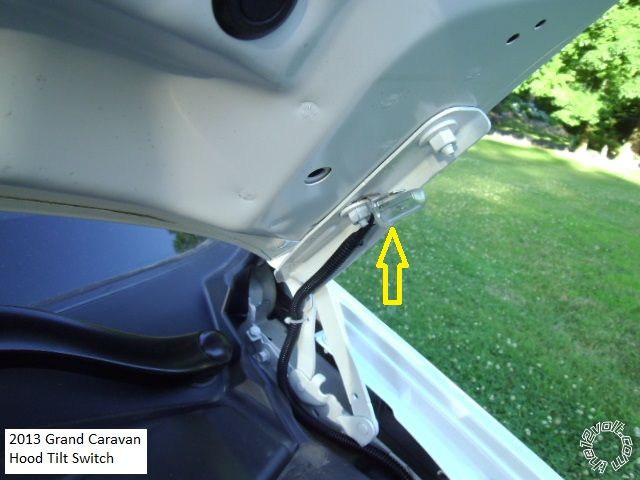
------------- Soldering is fun!
Posted By: willy1094
Date Posted: January 09, 2015 at 4:35 PM
I really like the idea of a mercury switch. How would it do parking on an incline? Is it a pretty drastic on off differ?
Thanks
kreg357 wrote:
Personally, I keep the R/S system and the bypass module under the drivers side dash area. The majority of the wires
can be found in that area. You could grab the door trigger wires at the BCM, diode isolate into one wire and pull that
one wire up to the front. Running thick ignition wires that distance could be problematic if not executed perfectly.
If your truck currently has RKE, do the interior lights come on with an Unlock command? If yes, you might not need
dome light supervision.
Can't help with the heated seats, sorry.
For the Tach, you might have to play around / trail and error to find what engine RPM at Learn works best for all
situations.
Not sure what your objection is to a hood pin. It is a nice safety feature. You are already running a wire into the
engine compartment for the Tach, so another wire for the hood pin shouldn't be an issue. I don't like drilling holes
for the hood pin, too much chance for rust, etc. My solution is using a mercury tilt switch mounted to an existing
hood hinge bolt. Like this :
<IMG src="https://www.the12volt.com/installbay/uploads/D9E_2013_gc_hood_pin_switch.jpg">
Posted By: kreg357
Date Posted: January 09, 2015 at 7:41 PM
You caught the main issue with the mercury tilt switch. When adjusted properly, the switch will only trigger with the hood
raised to 30 degrees, or so. If you lived in San Francisco and parked facing uphill, it might prevent a R/S. In most instances,
if you park on a somewhat level surface, it should work fine. The other issue is using mercury tilt switches in alarm applications.
An alarm should trigger before the hood is raised enough to get at any wiring and the 30 degrees opening provided by a tilt
switch is way too much. They are move expensive but provide a much longer service life compared to the standard pin switch.
-------------
Soldering is fun!
Posted By: willy1094
Date Posted: January 09, 2015 at 8:03 PM
I will go ahead and run the wire for the switch and try to work out a mounting method that will work for me. What are your thoughts on a labeled manual switch?
This post https://www.the12volt.com/installbay/forum_posts.asp?tid=136501 seems to indicate that I can use the dome for the door sense.
Posted By: willy1094
Date Posted: January 09, 2015 at 8:13 PM
Sorry, forgot to ask, what are your thoughts on the (+)12V connections? I think I go with the rear install running 14 gauge wire to the front. Nothing against your preference, I really like how installs turned out with other people's installations. Can you offer any insight with the amp vs BCM (+)12V connections?
Does the rest of my wiring connections listed work? Any good way to test negative current draw from a momentary switch?
Thanks for taking the time to reply.
Posted By: kreg357
Date Posted: January 09, 2015 at 8:32 PM
A manual switch for service mode can be done inside the vehicle, too. The Vipers Neutral Safety Switch provides this for you.
Another way to get an instant hood trigger is with a magnetic reed switch. Here is an example of a current listing on EBay :
https://www./itm/Normally-OPEN-NO-Magnetic-Contact-door-window-reed-switch-BLACK-2pairs-/301466010233?pt=LH_DefaultDomain_0&hash=item4630c64279
These could be secured in place with HotGlue. No rust, no holes and improved life span ( they are slightly more fragile ).
As for door triggers, I like using the actual door trigger wires, if they are the N.O. type. Less issues and more logical to me.
Here is a link to a wire gauge to amps and distance calculator : https://www.bulkwire.com/wireresistance.asp
You can use it to estimate the needed wire gauge for your runs to the steering column. Might also consider additional fuses. ------------- Soldering is fun!
Posted By: willy1094
Date Posted: January 09, 2015 at 8:46 PM
Thanks Kreg! Any thoughts or input on the (+)12V connections? Mainly, it it too much of a load to add to the amp wire or BCM? I'm leaning toward the amp since it is not a critical component. I could easily replace the amp. I'm just used to running new feeds for heavy load audio (amplifiers) and Leary of adding additional load to a circuit that may already be toward it's limit. The amp seems to be a pretty heavy wire for a factory amp.
Posted By: kreg357
Date Posted: January 10, 2015 at 2:15 AM
Sorry, I have never looked at / evaluated wires found at the BCM for use with R/S systems and ignition wires. As mentioned, I keep the R/S under the dash and draw supply power from the main ignition harness. It can handle the load and all the high amp wires are short.
-------------
Soldering is fun!
Posted By: willy1094
Date Posted: January 10, 2015 at 6:17 AM
kreg357 wrote:
Sorry, I have never looked at / evaluated wires found at the BCM for use with R/S systems and ignition wires. As mentioned, I keep the R/S under the dash and draw supply power from the main ignition harness. It can handle the load and all the high amp wires are short.
Thanks again. I may have to rethink my install location. Thinks for the link also. I've used voltage drop calculators for AC before but haven't used one for DC.
If anyone can offer input on the heated seats, that would be very helpful. I guess I could play it safe and use relays.
Posted By: willy1094
Date Posted: January 10, 2015 at 7:11 AM
Kreg, do you typically combine the 12V constant, 12V accessory/starter input, Fused 12V ignition 1 input and connect them to light GREEN/ purple at the ignition harness? If not, what would the best connection for these be if installing under the dash? I'm thinking I could install under the dash to keep these heavy wires short and then run the smaller wires back to the BCM if needed.
Posted By: willy1094
Date Posted: January 10, 2015 at 7:21 AM
willy1094 wrote:
Kreg, do you typically combine the 12V constant, 12V accessory/starter input, Fused 12V ignition 1 input and connect them to light GREEN/ purple at the ignition harness? If not, what would the best connection for these be if installing under the dash? I'm thinking I could install under the dash to keep these heavy wires short and then run the smaller wires back to the BCM if needed.
Sorry, I can't edit my posts yet but I just saw that I would connect the fused 12V ignition 1 input to the ignition 1 dark blue/light green at the ignition harness. So I guess my questions would be if I would combine the 12v constant and the 12v accessory/starter input?
Posted By: willy1094
Date Posted: January 10, 2015 at 7:32 AM
Scratch that last post. Both of those are for the relays. Sorry, I'm still working out these new (under dash) connections. Boy, I wish I could edit 
Posted By: willy1094
Date Posted: January 10, 2015 at 8:23 AM
OK, I think I have it worked out. I've got red 12V constant input to light GREEN/ purple, fused 12v accessory/starter input to light GREEN/ purple, fused 12v ignition 1 input to light green purple and ignition 1 input/output to dark blue/light green.
Do you have a preference of attaching the tach wire to the coil or fuel injector, or does it make a difference?
Posted By: kreg357
Date Posted: January 10, 2015 at 11:20 AM
My rule of thumb : Ford = F.I. and Chrysler = Coil
------------- Soldering is fun!
Posted By: willy1094
Date Posted: January 10, 2015 at 12:13 PM
This may be a stupid question...would it be better to grab one of the injectors at the rear of the engine as opposed to the front? Is there any concern about signal interference if I run it through too much of the engine compartment?
Posted By: kreg357
Date Posted: January 10, 2015 at 1:21 PM
I usually go for the F.I. that is easiest to get at the wires with a soldering iron. Never had any issues with interference due to the length of the run but I also protect the wire in 1/4" split tube loom.
-------------
Soldering is fun!
Posted By: willy1094
Date Posted: January 10, 2015 at 1:54 PM
kreg357 wrote:
I usually go for the F.I. that is easiest to get at the wires with a soldering iron. Never had any issues with interference due to the length of the run but I also protect the wire in 1/4" split tube loom.
Thanks for all your help! I've got everything planned out and I'm ready to do the install. I'll have to find a garage or a day that is not in the single digits.
Posted By: davep.
Date Posted: January 10, 2015 at 2:24 PM
When contemplating an installation where the Module will be a long distance from the Ignition Switch, another solution is to use the relay outputs instead of the on-board relays, and locate cube relays adjacent to the Ignition switch. Or find a "Satellite Relay" package from a circa 2008-2010 DEI RS system.
Then you can use light gauge wires for the relay triggers. No concerns about power draw from BCM wiring, etc. The one drawback on a Ford is that there are 4 IGN or ACCY to power up if you want everything to work during RS. I've found it easier to power them all instead of figuring out which ones do what, and don't have to be powered in an unoccupied car. So you'll have 5 relays. Still better /easier than running all those heavy wires from the rear of the cab.
Posted By: kreg357
Date Posted: January 10, 2015 at 6:08 PM
The drivers door sill has a very thick bundle of wires that can makes things easier :
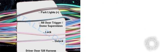
------------- Soldering is fun!
Posted By: willy1094
Date Posted: January 12, 2015 at 6:07 PM
Ok, good news! I did some playing around today with the wht/red wire. I used a logic probe and confirmed that the wire went to ground when you push the button. Then I used the multimeter to check out what kind of current went through the wire when the button was hit. This was the most troublesome area of my testing. It would range from 6 volts down to .09 volts.
I'm not sure I was doing the multimeter testing correctly. I put the red probe to a hot wire and then the black to the wht/red wire and would hit the button (this was awkward to do by myself). I'm not sure if this test really told me if the 200mA is enough or now since it was probably just trying to read the full 12V current for the wire I had the red probe to. If you or anyone else can clue me into how to test this, that would be great. Maybe red to ground and black to the wht/red???
Anyway, to the good news. I very cautiously/nervously used a jumper wire and grounded the wire and sure enough, high heat. I grounded it again and it went to low and then to off. I am inclined to think that this is hitting a relay and trigger the seats but unless someone can help me figure it out, I guess I relay both of these wires. I'm just happy that I will have a remote function for my heated seats.
These wires are something like 24 AWG and I'm thinking of using taps here instead of soldering. I know taps are the devil but these are not a "critical connection and will not have constant current. I will cheat though. I plan on cutting back the insulation and sliding the wire into the prongs to make sure they don't get cut and that I have good contact. I'm going to solder everything else.
I just have to say, for now, I'm VERY happy that I decided to do this install DIY.
Posted By: willy1094
Date Posted: January 12, 2015 at 6:29 PM
It just dawned on me that I should have been checking amps, not volts, when testing this wire. I'm still not 100% sure I know how this is done. Do I just switch my (+) probe to the AMPs plug and put it to ground, then the (-) probe to the wire and hit the button?
Thanks
Posted By: willy1094
Date Posted: January 13, 2015 at 8:46 PM
I got out to locate all the wires and have a couple questions. The horn wire is a lot heavier wire than the one one the RS ( a lot might be an exaggeration) Second question is for the parking lights. I have two brown wires behind the switch. According to my test probe, they both go positive when I turn the switch on. Which one do I use? I'll check my wire schematic but wanted to ask in case I can't figure it out.
Thanks
Posted By: willy1094
Date Posted: January 15, 2015 at 12:10 PM
Well, I got the remote start installed and it unlocks, locks and starts but I did notice a couple issues today. Since getting the RS installed, my high beam indicator does not come on. I will have to check to make sure the high beams themselves come on when I get home (noticed this on my lunch break). I will try investigating this more but could use some tips. Any reason why installing a RS would cause this? Also, sometime the computer display lights up when remote started and sometimes it does not. It does come on once I turn the key to run and hit the brake.
Posted By: willy1094
Date Posted: January 25, 2015 at 1:15 PM
Hello
I just thought I'd give an update. The remote start is installed and everything is working well. My "issues" all came from my use of the dome light as the door sense. I switched to the the 4 wires at the BCM and everything is fine. I even got the heated seats to come on remotely. Thanks for the help
|