Remote start for Tundra 2009
Printed From: the12volt.com
Forum Name: Car Security and Convenience
Forum Discription: Car Alarms, Keyless Entries, Remote Starters, Immobilizer Bypasses, Sensors, Door Locks, Window Modules, Heated Mirrors, Heated Seats, etc.
URL: https://www.the12volt.com/installbay/forum_posts.asp?tid=138706
Printed Date: May 03, 2024 at 2:08 AM
Topic: Remote start for Tundra 2009
Posted By: jacky_needhelp
Subject: Remote start for Tundra 2009
Date Posted: March 23, 2015 at 6:47 AM
How do I connect this part? Question in the diagram in blue ink. Tundra 2009 standard key and 4706V with Dball2

Replies:
Posted By: kreg357
Date Posted: March 23, 2015 at 7:00 AM
The actual, power supplying, ignition source during a remote start is the R/S brain, not the DB-ALL2. You would use the Vipers
thick Pink/White IGN2 output wire to power the Tundra's IGN2 wire. The DB-ALL2 uses that ignition feed shown as an input only.
So, Viper thick Pink to Tundra IGN1 and DB-ALL2. Viper Pink/White to Tundra IGN2. ------------- Soldering is fun!
Posted By: jacky_needhelp
Date Posted: March 23, 2015 at 7:06 AM
According to what I understand:
Viper thick Pink connecting to DB-Ball 2 and then to the Tundra IGN 1 as shown in the diagram.
The Pink/White go directly to the Ign 2 of the Tundra with no connection to the Dball2
Posted By: jacky_needhelp
Date Posted: March 23, 2015 at 7:11 AM
Confirm please
Posted By: kreg357
Date Posted: March 23, 2015 at 7:12 AM
That is correct. The diagram is somewhat generic. Some Toyota's will have two Starter wires and only one Ignition wire, some have two of each, etc.
-------------
Soldering is fun!
Posted By: jacky_needhelp
Date Posted: March 23, 2015 at 7:23 AM
Terrific.
What about his one in the red Ink? I know second starter will need a relay. Is the one that I circled with the red circle consider the second starter connection?
I haven't got the RS unit or the DBALL2 nor looking at the car yet.

Posted By: jacky_needhelp
Date Posted: March 23, 2015 at 7:26 AM
Or Is that for Manual Transmission only?
Posted By: kreg357
Date Posted: March 23, 2015 at 7:31 AM
The 2009 Tundra has two Ignition wires, one Starter wire and one Accessory wire. That connection to the clutch interlock switch is only necessary if you have a manual transmission.
-------------
Soldering is fun!
Posted By: jacky_needhelp
Date Posted: March 23, 2015 at 7:41 AM
Sorry one more question: In the light blue circle.

Posted By: howie ll
Date Posted: March 23, 2015 at 8:10 AM
Yes. On your diagram the solid wires only when using D2D, all the wires shown solid and dotted when using W2W.
-------------
Amateurs assume, don't test and have problems; pros test first. I am not a free install service.
Read the installation manual, do a search here or online for your vehicle wiring before posting.
Posted By: jacky_needhelp
Date Posted: March 25, 2015 at 6:27 AM
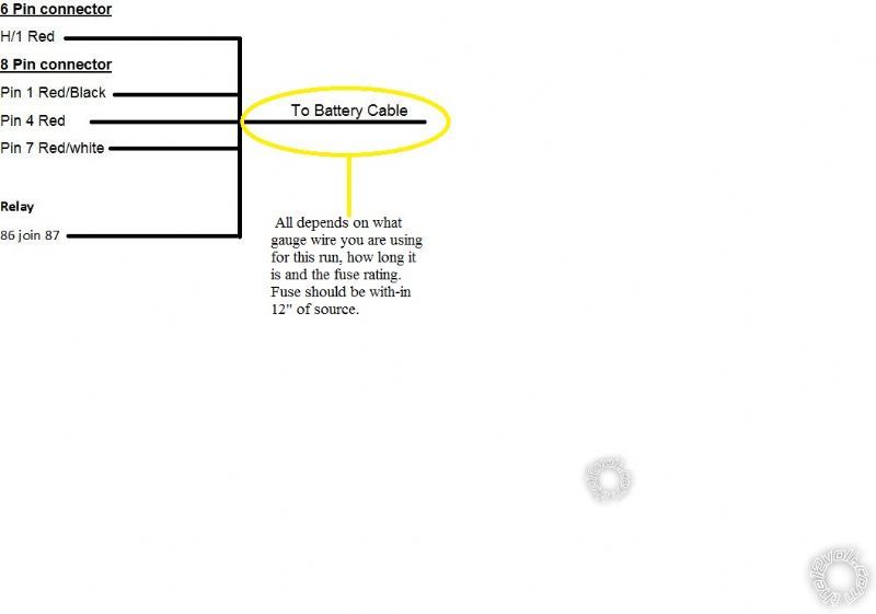
When connecting the 12V DC, can all the 12VDC wires from the viper join together including the one that connects to the 86+87 of the relay to the 12VDC of the BCM. Or the one that goes to the relay has to be connect to a different 12VDC like at the key switch.
Posted By: jacky_needhelp
Date Posted: March 25, 2015 at 6:50 AM
Here is the plan to connect all the wires to the 12VDC Battery Cable.

Posted By: kreg357
Date Posted: March 25, 2015 at 7:14 AM
 ------------- Soldering is fun!
Posted By: kreg357
Date Posted: March 25, 2015 at 7:19 AM
What's the extra relay for? The Viper can directly handle the trucks four ignition wires.
-------------
Soldering is fun!
Posted By: jacky_needhelp
Date Posted: March 25, 2015 at 7:40 AM
I'm not sure what gauge is the battery cable to the fuse box, but the one from the Viper must be around 20-24 gauge.
When you are talking about the distance from the source and the fuse, can you clarify which of the below is right?

Posted By: jacky_needhelp
Date Posted: March 25, 2015 at 7:40 AM
The relay is for the second starter
Posted By: howie ll
Date Posted: March 25, 2015 at 7:48 AM
This is very similar, either a black or white thick wire as your source going to either fusebox or BCM, then you need only use the existing fuses.
183_tacoma_wiring.bmp
It's for a Tacoma but essentially similar provided this isn't a PTS. ------------- Amateurs assume, don't test and have problems; pros test first. I am not a free install service.
Read the installation manual, do a search here or online for your vehicle wiring before posting.
Posted By: jacky_needhelp
Date Posted: March 25, 2015 at 8:19 AM
That diagram shows 30 and 50 amp fuses. Does it matter if I use 20amp fuse. What is the difference?
Posted By: howie ll
Date Posted: March 25, 2015 at 8:24 AM
Sorry it's supposed to mean battery to OEM fuses to ignition switch.
Take your two reds, 15 and 30 amp fuses, RED / black, RED / white and extra 30 amp fused feed for second starter from the thick feed cable.
-------------
Amateurs assume, don't test and have problems; pros test first. I am not a free install service.
Read the installation manual, do a search here or online for your vehicle wiring before posting.
Posted By: jacky_needhelp
Date Posted: March 25, 2015 at 8:35 AM
You meant
Take the two reds, 15 and 30 amp fuses, RED / black, RED / white and extra wire with a 30 amp fuse that's for the second starter to feed into the thick feed cable (fusebox or BCM).
Posted By: jacky_needhelp
Date Posted: March 27, 2015 at 4:07 PM
Do I need to install a relay for a second starter, since my truck has two 12VDC. Planning to have it install tomorrow. Appreciate if anyone can respond.
Posted By: howie ll
Date Posted: March 27, 2015 at 4:59 PM
Already explained. Look at my link on the previous page.
-------------
Amateurs assume, don't test and have problems; pros test first. I am not a free install service.
Read the installation manual, do a search here or online for your vehicle wiring before posting.
Posted By: smokeman1
Date Posted: March 27, 2015 at 5:10 PM
Test and Verify all wires with a DMM prior to making any connections
From you heavy gauge connector:
RED / Black, Red, RED / White, and the Red from the main harness as well as the DB-ALL, Pin 13, Red on the 14 pin connector, to 12 Volts constant...Black @ Dash Fuse Box
Pink to Ignition 1....Black @ Ignition Harness
Pink/White Ignition 2.....Light Green @ Ignition Harness
Violet Starter.....Green @ Ignition Harness
Orange Accessory.....Gray @ Ignition Harness.
https://www.bulldogsecurity.com/bdnew/vehiclewiringdiagrams.aspx
If Tundra is an automatic, ground the BLACK/ White(pin 13 from 24 pin harness) along with the Black from the 6 pin main harness.
I don't see anything that indicates the Tundra has a second starter so no relay needed.
-------------
When all else fails, Read the Instructions
Support the12volt.com Make a Donation
Posted By: kreg357
Date Posted: March 27, 2015 at 5:40 PM
Ah, Mr. Smoke, you beat me to the post.  But I spent so much time making a swell diagram, here goes anyway. But I spent so much time making a swell diagram, here goes anyway.
( It's just a rehash of your excellent info.)
Info from Bulldog Security :
12 VOLT CONSTANT BLACK (+) @ DASH FUSE BOX, WHITE 1-PIN PLUG (DA), Pin 1
STARTER GREEN (+) @ IGNITION SWITCH HARNESS, WHITE 8-PIN PLUG, PIN 7
IGNITION 1 BLACK (+) @ IGNITION SWITCH HARNESS, WHITE 8-PIN PLUG, PIN 6
IGNITION 2 LT. GREEN (+) @ IGNITION SWITCH HARNESS, WHITE 8-PIN PLUG, PIN 1
ACC/HEATER BLOWER 1 GRAY (+) @ IGNITION SWITCH HARNESS, WHITE 8-PIN PLUG, PIN 2
Info from ReadyRemote :
12volts black (140A or 150A) + dash fuse box, white 1 pin plug (DA), pin 1
Starter green + ignition switch, white 8 pin plug, pin 7
Ignition black + ignition switch, white 8 pin plug, pin 6
Second Ignition lt. green + ignition switch, white 8 pin plug, pin 1
Accessory gray + ignition switch, white 8 pin plug, pin 2
Info from Omega :
Constant 12 volts BLACK AT FUSE BLOCK
Ignition 12 volts BLACK @ IGNITION SWITCH HARNESS
Starter GREEN @ IGNITION SWITCH HARNESS
Ignition #2 LT GREEN @ IGNITION SWITCH HARNESS
Accessory GRAY @ IGNITION SWITCH HARNESS
Audiovox has the exact same info :
All of the general wiring sources agree and that is exactly what I have found on the 2009 - 2010 Tundra's that I have done. So, with
that info and your chosen Viper system, this is how I would make the ignition connections :
Remote Start, 8-pin connector
1 RED / BLACK (+) 12VDC CONSTANT BLACK (+) @ DASH FUSE BOX, WHITE 1-PIN PLUG (DA), Pin 1
2 PINK/BLACK (+) FLEX RELAY INPUT 87A not used
3 PINK/WHITE (+) IGNITION 2 / FLEX RELAY LT. GREEN (+) @ IGNITION SWITCH HARNESS, WHITE 8-PIN PLUG, PIN 1
4 RED (+) 12VDC CONSTANT INPUT BLACK (+) @ DASH FUSE BOX, WHITE 1-PIN PLUG (DA), Pin 1
5 VIOLET (+) STARTER OUTPUT GREEN (+) @ IGNITION SWITCH HARNESS, WHITE 8-PIN PLUG, PIN 7
6 ORANGE (+) ACCESSORY OUTPUT GRAY (+) @ IGNITION SWITCH HARNESS, WHITE 8-PIN PLUG, PIN 2
7 RED / WHITE (+) 12VDC CONSTANT INPUT BLACK (+) @ DASH FUSE BOX, WHITE 1-PIN PLUG (DA), Pin 1
8 PINK (+) IGNITION 1 INPUT/OUTPUT BLACK (+) @ IGNITION SWITCH HARNESS, WHITE 8-PIN PLUG, PIN 6
plus DB-ALL2 black 10 Pin plug, Pin 9 Pink
As mentioned before, all the ignition wires at the ignition switch harnesses are 16 - 18 gauge so you could fuse down the three
H3 Red, RED / xxx +12V constant input wires. Personally, I would position the Viper near the fuse box and do it this way :
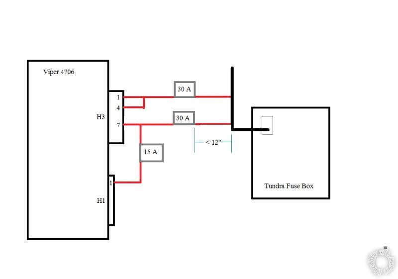
------------- Soldering is fun!
Posted By: tedmond
Date Posted: March 27, 2015 at 6:20 PM
I will add the diagram is not to scale  x2 with kreg though for a detailed post. ------------- Ted
2nd Year Tier 1 Medical School
Still installing as a hobby...pays for groceries
Compustar Expert
Posted By: smokeman1
Date Posted: March 27, 2015 at 6:49 PM
Well Kreg, You always do the extensive research on these posts which is way more detailed then my post.
Nice diagram though. It's not often I beat you to a post. 
Anyway, I was just putting out enough info to get the guy started.
------------- When all else fails, Read the Instructions
Support the12volt.com Make a Donation
Posted By: howie ll
Date Posted: March 27, 2015 at 6:58 PM
Those diagrams got me to thinking.
The earlier Clifford stuff, AG3/4/5 had separate fuses and much longer feed wires.
You could place the fuse correctly, that is within 4" of your source. The current DEI stuff has the fuses at the brain, WRONG!.
Apart from which the wire quality is awful on current product.
Sorry I listed a diagram with two starters, it was one I did a couple of years ago in another post, bloody heck I've never seen a bloody Tacoma.
Only ever done 1 Land Cruiser and what a PITA, PTS and you have to open up the BCM to get at TX and RX, not pre-wired as on North American versions.
-------------
Amateurs assume, don't test and have problems; pros test first. I am not a free install service.
Read the installation manual, do a search here or online for your vehicle wiring before posting.
Posted By: tedmond
Date Posted: March 27, 2015 at 7:13 PM
I rarely use the entire length of the constants. Often times I'm trimming off 3-6 inches if the wires go to the ignition. I have to agree that the current generation 5x0x series brains can use some work. Although an improvement on form factor, the colour coding system has gone to the gutter. Multiple wires of the same colour, no shading between them! I had benched prep a unit brought to me, and during the install; I was forced to cut open my prep just to trace my wires. This is only on the 5706/5906. The older 5901/2 early 5904/6 didn't have these problems.
Then again, I don't touch DEI flagships (viper/python/clifford) often.
-------------
Ted
2nd Year Tier 1 Medical School
Still installing as a hobby...pays for groceries
Compustar Expert
Posted By: jacky_needhelp
Date Posted: March 27, 2015 at 7:21 PM
My tundra does come with two starters and two 12VDC constant, 2 Ignitions, and an ACC. Testing with DMM this afternoon. This is why I am wondering if I need a relay for the second starter. I am sure I will need one relay if I have two starters. Asking you guys because I just want to be more than sure.
Posted By: jacky_needhelp
Date Posted: March 27, 2015 at 7:26 PM
Thanks kreg357 for the suggested wiring diagram
Posted By: howie ll
Date Posted: March 27, 2015 at 7:33 PM
If you think it has two starters, then for the THIRD time use this link.
Shows you how to use the relay, diode etc.
183_tacoma_wiring.bmp
-------------
Amateurs assume, don't test and have problems; pros test first. I am not a free install service.
Read the installation manual, do a search here or online for your vehicle wiring before posting.
Posted By: smokeman1
Date Posted: March 27, 2015 at 7:59 PM
Only you can determine if you have a second starter with your DMM. All of the wire guides only list one starter. If you need the second starter,yes a relay willbe required. Follow Howies advice on the setup.
-------------
When all else fails, Read the Instructions
Support the12volt.com Make a Donation
Posted By: howie ll
Date Posted: March 28, 2015 at 4:08 AM
Ted's post got me to thinking, how's about separating those violet, violet/black, WHITE/ black and WHITE/ violet H2 wires underdash and a dark day, I'll say no more.
-------------
Amateurs assume, don't test and have problems; pros test first. I am not a free install service.
Read the installation manual, do a search here or online for your vehicle wiring before posting.
|