2014 Toyota Camry Viper 5706v with Fortin EVO-Al
Printed From: the12volt.com
Forum Name: Car Security and Convenience
Forum Discription: Car Alarms, Keyless Entries, Remote Starters, Immobilizer Bypasses, Sensors, Door Locks, Window Modules, Heated Mirrors, Heated Seats, etc.
URL: https://www.the12volt.com/installbay/forum_posts.asp?tid=138953
Printed Date: May 02, 2024 at 4:44 AM
Topic: 2014 Toyota Camry Viper 5706v with Fortin EVO-Al
Posted By: wramsey12
Subject: 2014 Toyota Camry Viper 5706v with Fortin EVO-Al
Date Posted: May 11, 2015 at 8:39 AM
I was searching for installs with my car and the Viper 5706v and Fortin Evo-All and didn't see anything listed. I did see this post https://www.the12volt.com/installbay/forum_posts.asp?tid=138166 which is talking about D2D between the 5706V and the Evo-All where someone said you just had to use the D2D wire between them and wire the Evo-All correctly. I was just curious if this is true for the Camry because the wiring instructions I have from the Evo-All shows that you have to have the Data-Link cable between the Evo-All and the 5706v as well as the while running ground wire and other wires from the 5706V to different pins on the ignition harness but the documentation does not match up with the 5706v wiring documentation I got from here. For instance, the Evo-All shows Remote Start 1 as Ground when it's actually the Main Harness pin 2 for ground for the 5706V. I know this doesn't really matter for this one but I'm also not sure on others. For example, the main harness pin 1 goes to 12vdc constant input which I'm understanding to be 12v battery from Pin 5 on the Ignition Harness but Remote start 2 is an input for 12v accessory/starter on the 5706v which I'm showing should be an output according to the evo-all documentation. From my understanding output on the 5706v should go out to the car while inputs should come in from the carbut the evo-all paperwork only shows one input and that's the 12v ground so which is correct? All help is greatly appreciated. I also uploaded the Evo-All manual I have to the downloads/manuals if that would help.
Replies:
Posted By: wramsey12
Date Posted: May 12, 2015 at 6:24 PM
After looking at my Viper system once I got it and looking at the install document I have for the EVO-All this is what I came up with wiring wise. The ones with the ?'s I wasn't sure where they connected or if they did at all. I'm attaching a screen grab of the Excel wiring diagram that is listed here with my connections. Any help would be much appreciated

Posted By: kreg357
Date Posted: May 12, 2015 at 8:30 PM
Viper 5706 2014 Camry regular key ignition EVO-ALL flashed with DBI 6.79.25
Main Harness, 6-pin connector
1 RED (+)12VDC CONSTANT INPUT GREEN (+) @ IGNITION SWITCH HARNESS, WHITE 8-PIN PLUG, PIN 5
2 BLACK (-) CHASSIS GROUND Chassis Ground
3 BROWN (+) SIREN OUTPUT Viper siren
4 WHITE/ BROWN PARKING LIGHT ISOLATION - PIN 87a not used
5 WHITE PARKING LIGHT OUTPUT *** Set to (-) BLACK (-) @ 20 Pin Headlight Switch Plug
6 ORANGE (-) 500mA GROUND WHEN ARMED OUTPUT not used
Door Lock, 3-pin connector
1 BLUE (-) 500mA UNLOCK OUTPUT Via D2D
2 EMPTY NOT USED
3 GREEN (-) 500mA LOCK OUTPUT Via D2D
Remote Start, 10-pin heavy gauge connector
1 NC No Connection
2 RED / BLACK (+) FUSED 12V ACC/STARTER INPUT GREEN (+) @ IGNITION SWITCH HARNESS, WHITE 8-PIN PLUG, PIN 5
3 PINK/BLACK (+) FLEX RELAY INPUT 87A not used
4 PINK/WHITE (+) IGNITION 2 / FLEX RELAY OUTPUT PINK (+) @ IGNITION SWITCH HARNESS, WHITE 8-PIN PLUG, PIN 1 * set to IGN2
5 RED (+) FUSED 12V IGNITION 1 INPUT GREEN (+) @ IGNITION SWITCH HARNESS, WHITE 8-PIN PLUG, PIN 5
6 GREEN (+) STARTER INPUT (KEY SIDE) BLUE (+) @ IGNITION SWITCH HARNESS, WHITE 8-PIN PLUG, PIN 7
7 VIOLET (+) STARTER OUTPUT (CAR SIDE) BLUE (+) @ IGNITION SWITCH HARNESS, WHITE 8-PIN PLUG, PIN 7
8 ORANGE (+) ACCESSORY OUTPUT not used - according to EVO-ALL diagram
9 RED / WHITE (+) FUSED 12V IGNITION 2 GREEN (+) @ IGNITION SWITCH HARNESS, WHITE 8-PIN PLUG, PIN 5
10 PINK (+) IGNITION 1 INPUT/OUTPUT BLACK (+) @ IGNITION SWITCH HARNESS, WHITE 8-PIN PLUG, PIN 6
Auxiliary/Shutdown/Trigger Harness, 24-pin connector
1 PNK/WHITE (-) 200mA Ignition 2/Flex OUTPUT not used
2 BLUE/WHITE (-) 200mA 2ND STATUS /REAR DEFOG not used
3 RED / WHITE (-) 200mA TRUNK RELEASE OUTPUT Via D2D
4 BLACK / YELLOW (-) 200mA DOME LIGHT OUTPUT not used
5 DARK BLUE (-) 200mA STATUS OUTPUT to EVO-ALL A8
6 WHITE/ BLACK (-) 200mA AUX 3 OUTPUT not used
7 WHITE/ VIOLET (-) 200mA AUX 1 OUTPUT not used
8 ORANGE / BLACK (-) 200mA AUX 4 OUTPUT not used
9 GRAY (-) HOOD PIN INPUT (NC OR NO) Via D2D if vehicle has factory hood pin
10 BLUE (-) TRUNK PIN (N/C OR N/O) Via D2D
11 WHITE/ BLUE ACTIVATION INPUT not used
12 VIOLET/WHITE* TACHOMETER INPUT Via D2D
13 BLACK/ WHITE** (-) NEUTRAL SAFETY Via D2D
14 GREEN/ BLACK (-) 200mA FACTORY ALARM DISARM Via D2D
15 GREEN* (-) DOOR INPUT Via D2D
16 BROWN / BLACK (-) 200mA HORN HONK OUTPUT optional
17 PINK (-) 200mA IGNITION 1 OUTPUT not used
18 VIOLET* (+) DOOR INPUT not used
19 VIOLET/BLACK (-) 200mA AUX 2 OUTPUT not used
20 BROWN (+) BRAKE SHUTDOWN INPUT Via D2D
21 VIOLET / YELLOW (-) 200mA STARTER OUTPUT to Pin 85 of external relay
22 GRAY/BLACK (-) DIESEL WAIT TO START INPUT not used
23 ORANGE (-) 200mA ACCESSORY OUTPUT not used
24 GREEN / WHITE (-) 200mA FACTORY ALARM ARM Via D2D
Extra 30/40 Amp SPDT relay
Relay Pin 85 to Viper 21 VIOLET / YELLOW (-) 200mA STARTER OUTPUT
Relay Pins 86 and 87 to Yellow @ Pin 4 of Ignition Switch Harness through 7.5 Amp fuse
Relay Pin 30 to lt. green + ignition switch, white 8 pin plug, pin 3
Relay Pin 87a not used - insulate
Better yet, for all the +12V constant power connections, look for a very thick Black wire at the front of the fuse box. ------------- Soldering is fun!
Posted By: wramsey12
Date Posted: May 12, 2015 at 9:05 PM
Kreg, thank you very much for the reply. This will help tremendously, I will post if I need anymore help.
Posted By: howie ll
Date Posted: May 13, 2015 at 8:50 AM
You also made a glaring error on your Excel sheet and you may not have noticed that Kreg gave you the right answer.
You have TWO starter wires.
Cut the BLUE, vehicle starter wire #1
H3 Green to key side and H3 Violet (purple) to motor side.
Use the relay as Kreg showed for the 2nd. starter, BUT solder a diode 1N4004 across the 86 and 85 terminals, band to 86. It's a precaution that may save you a burnt out circuit board on the Viper.
-------------
Amateurs assume, don't test and have problems; pros test first. I am not a free install service.
Read the installation manual, do a search here or online for your vehicle wiring before posting.
Posted By: wramsey12
Date Posted: May 13, 2015 at 9:54 AM
Reason I had two is because my wiring from Fortin showed 2 starter wires so I wasn't sure on it. The wiring page I got from Fortin shows starter 1 is blue ignition switch pin 7 and starter 2 is light green ignition switch pin 3. I appreciate all of the help and will take your advice on soldering that diode between those two terminals. One question, what would be the best place to get that diode from?
Posted By: howie ll
Date Posted: May 13, 2015 at 10:03 AM
Virtually any electrical repair place. We buy 100 multiples so we go to Farnel, Mouser etc. doubt if they sell less than 10 at a time. Any Radio Shacks left near you?
-------------
Amateurs assume, don't test and have problems; pros test first. I am not a free install service.
Read the installation manual, do a search here or online for your vehicle wiring before posting.
Posted By: wramsey12
Date Posted: May 13, 2015 at 10:12 AM
Yeah I think there is a radio shack. I will look this evening on the way to work. As it is we are due for rain the next three days so I won't be doing this build until probably next week. I just wanted to get all the details before I started doing anything. I've had experience wiring radios and amps and such as well as electronics and computer but had never done a remote start so was just going off intuition when comparing the wiring diagram from the viper and what I got for my camry from fortin. I will look there and at a few other electrical repair places around.
Posted By: wramsey12
Date Posted: May 13, 2015 at 10:21 AM
Just out of curiosity what is the second starter wire that's listed in the wiring diagram from Wirecolor for. I misspoke when I said it was from Fortin, my bad. I got a chart of wires and colors from wirecolor and it shows pin 3 is starter 2 and is a light green color.
Posted By: howie ll
Date Posted: May 13, 2015 at 10:27 AM
That second starter wire is the one Kreg told you to use the relay for.
Usually used as a cold weather starting aid.
Do not join the two, wire as Kreg said. Toyota separates them for a reason, so should you.
-------------
Amateurs assume, don't test and have problems; pros test first. I am not a free install service.
Read the installation manual, do a search here or online for your vehicle wiring before posting.
Posted By: wramsey12
Date Posted: May 13, 2015 at 10:28 AM
Alright will do. Just wasn't sure and was curious.
Posted By: howie ll
Date Posted: May 13, 2015 at 10:32 AM
Thinking about chassis ground. On Toyotas there are many, most 10mm, some 12mm spanner size bolts in the kickwell. Use one of them with the paintwork scraped to bare metal, buy a 6mm (10mm spanner) or 8mm (12mm spanner) ring terminal, red colour code, also Radio Shack etc.(6mm = 1/4", 8mm =5/16").
Don't use an existing grounding point there can be inducted interference problems.
-------------
Amateurs assume, don't test and have problems; pros test first. I am not a free install service.
Read the installation manual, do a search here or online for your vehicle wiring before posting.
Posted By: wramsey12
Date Posted: May 13, 2015 at 10:53 AM
Another question I had is Kregs post says to flash the evo-all with DBI 6.79.25. All I'm showing from the flash link manager is 79.24 and 79.25 beta. Are you referring to the beta firmware or is it a firmware that isn't available through the flash link manager?
Posted By: howie ll
Date Posted: May 13, 2015 at 10:55 AM
No idea, sorry, you'll have to ask Kreg.
Or better still call Fortin.
I've had to do it from the UK.
Mind you .25 beta should be the same.
-------------
Amateurs assume, don't test and have problems; pros test first. I am not a free install service.
Read the installation manual, do a search here or online for your vehicle wiring before posting.
Posted By: wramsey12
Date Posted: May 13, 2015 at 11:01 AM
Alright thanks. I will use your suggestion on the ground wire stuff and will try to get in touch with Fortin between now and doing this install. Maybe Kreg will respond with some help. Thanks again to you both.
Posted By: howie ll
Date Posted: May 13, 2015 at 11:03 AM
You might have to wait for Kreg, he sometimes works night shifts.
-------------
Amateurs assume, don't test and have problems; pros test first. I am not a free install service.
Read the installation manual, do a search here or online for your vehicle wiring before posting.
Posted By: wramsey12
Date Posted: May 13, 2015 at 11:13 AM
Alright no worries. I'm same way just happened to be up as I hadn't made it to bed yet but am turning in now.
Posted By: howie ll
Date Posted: May 13, 2015 at 11:16 AM
Huh? I'm having dinner in 3 hours, it's 5:15pm.  ------------- Amateurs assume, don't test and have problems; pros test first. I am not a free install service.
Read the installation manual, do a search here or online for your vehicle wiring before posting.
Posted By: wramsey12
Date Posted: May 13, 2015 at 11:20 AM
It's 11am here. Kreg pmd me with the info. Thanks again to both of you and I am very glad I found this forum as I'm in the country with the only viper installer within a hundred miles being best buy and they have a bad track record in this area for car electronics so I don't trust them plus their high fees
Posted By: howie ll
Date Posted: May 13, 2015 at 11:22 AM
Wish I could help you more but Cams, Maxis and Legends all got wiped out around 03 in Europe, killed by Audi and BMW.
-------------
Amateurs assume, don't test and have problems; pros test first. I am not a free install service.
Read the installation manual, do a search here or online for your vehicle wiring before posting.
Posted By: wramsey12
Date Posted: May 13, 2015 at 5:46 PM
It's alright Howie. You have helped me quite a bit you and kreg. It looks like Kreg was referring to the flash protocol D2D which is option f3 on flash link manager. I got it programmed to that protocol as it didn't have any D2D protocols set to it. Now I just need to get the rest of the stuff and this rain to let up. Hopefully by the end of the weekend I can get it installed.
Posted By: wramsey12
Date Posted: May 14, 2015 at 3:01 AM
Hey Howie when you mentioned soldering the diode across the terminals you said solder across 85 and 86 but band to 86 what exactly do you mean when you say band to 86?
Posted By: howie ll
Date Posted: May 14, 2015 at 3:18 AM
You'll see a band to one side of the diode, that's the band, denotes cathode, read the section here on diodes please.
-------------
Amateurs assume, don't test and have problems; pros test first. I am not a free install service.
Read the installation manual, do a search here or online for your vehicle wiring before posting.
Posted By: wramsey12
Date Posted: May 14, 2015 at 4:00 AM
Will do. Thought you were meaning something else. Man it's been a long day.
Posted By: wramsey12
Date Posted: May 14, 2015 at 7:44 AM
Kreg you said 5 WHITE PARKING LIGHT OUTPUT *** Set to (-). Do you mean to set the polarity on it to - via a relay as it shows in the how to switch polarity guide or did you just mean to connect it to - on the headlight switch? Thanks again for all of the help.
Posted By: kreg357
Date Posted: May 14, 2015 at 7:57 AM
The Viper has an internal Jumper / Fuse that you use to set the polarity of the White Parking Light Output wire. Think they come set to (+) from the factory if they don't pop out during shipping...  You will be connecting it to the cars' (-) Parking Light wire as shown in the EVO-ALL diagram. You will be connecting it to the cars' (-) Parking Light wire as shown in the EVO-ALL diagram.
Here is a link to more relay info : https://www.bcae1.com/relays.htm
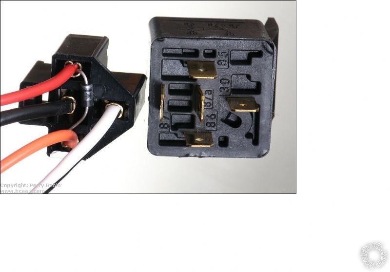
Here is a photo of the relay coil quenching diode installed as Howard mentioned :
( Warning : In the photo, it appears the diodes band is towards Relay Pin 85, which would go against standard relay conventions and make Pin 85 the (+) input side of the coil. Follow the previously posted wiring with Howards additions about 1N4007 diode with band towards Pin 86. )
------------- Soldering is fun!
Posted By: howie ll
Date Posted: May 14, 2015 at 8:27 AM
Kreg mentioned 1N4007 whilst I mentioned 1N4004. Just testing you.
The answer therefore to your next question is "it doesn't matter"
The higher the last digit, the higher the voltage reversal it can handle.
Anything from 1N4004 up is acceptable, although 1N4004 is the most common type available.
Look at the diagram you get with the 5706, that shows jumper fuse placement; (-) NEG setting please.
-------------
Amateurs assume, don't test and have problems; pros test first. I am not a free install service.
Read the installation manual, do a search here or online for your vehicle wiring before posting.
Posted By: wramsey12
Date Posted: May 14, 2015 at 9:12 PM
Alright gotcha...thanks for the help. I was wondering what that fuse was doing just running around loose in that compartment was. Thanks for clearing that up.
Posted By: howie ll
Date Posted: May 15, 2015 at 3:47 AM
Don't worry the first of those I did some years ago I wondered why no light flashers!
Installers diagnostic, test, if it doesn't work, kick it, still not working?
RTFM.
-------------
Amateurs assume, don't test and have problems; pros test first. I am not a free install service.
Read the installation manual, do a search here or online for your vehicle wiring before posting.
Posted By: wramsey12
Date Posted: May 16, 2015 at 7:17 AM
I looked around and apparently my electrical supply stores suck. I couldn't find the 30/40 but they had a 30/50 relay. From my understanding 30/50 will work in the place of 30/40 right because it's at least the same amperage as the 30/40? Please correct me if I'm wrong.
Posted By: howie ll
Date Posted: May 16, 2015 at 7:21 AM
Yes it will, but try an auto supply store, the 30/40 is standard and probably cheaper, OR use a simple 4 terminal, the switching NC side 87a isn't used anyway. A breakers
yard should have thousands!
-------------
Amateurs assume, don't test and have problems; pros test first. I am not a free install service.
Read the installation manual, do a search here or online for your vehicle wiring before posting.
Posted By: wramsey12
Date Posted: May 16, 2015 at 9:27 AM
Radioshack had the 30/50 for 2 bucks....I went ahead and got it. I should have tried autozone or oreillys but it's a crap shoot if they would have had the 30/40 for cheaper than what I gave for it. Our radioshack is locally owned so their prices are a bit different than what's on the website...not sure how they get away with that but they do so...and they are still in business unlike a lot of other stores
Posted By: howie ll
Date Posted: May 16, 2015 at 9:35 AM
Franchise operation, as long as they return a certain amount to head office they can stay in business.
The regular type costs me about $2.40 though X 10 I get them down to $1.50.
Component prices are about the same either side of the pond but as for the finished article, don't ask.
Let us just say that the first few days of any US vacation were spent chasing down a Snap-On truck and buying cordless tools.
Having said that my Milwaukee 12V compact screwdriver and 12V compact combi drill list at £300 ($450) here, I paid £200 ($300) for the pair with judicious shopping via Amazon (UK).
-------------
Amateurs assume, don't test and have problems; pros test first. I am not a free install service.
Read the installation manual, do a search here or online for your vehicle wiring before posting.
Posted By: wramsey12
Date Posted: May 17, 2015 at 7:03 AM
Kreg said to relay pins 86 and 87 through a fuse to pin 4 of ignition switch. I'm assuming you mean to run from relay pin 86 with an inline fuse holder to pin 4 of the ignition switch and do the same for pin 87? Thanks for the help.
Posted By: howie ll
Date Posted: May 17, 2015 at 8:23 AM
86 and 87 are common.
-------------
Amateurs assume, don't test and have problems; pros test first. I am not a free install service.
Read the installation manual, do a search here or online for your vehicle wiring before posting.
Posted By: wramsey12
Date Posted: May 17, 2015 at 9:51 AM
Ah ok
Posted By: wramsey12
Date Posted: June 14, 2015 at 6:53 AM
Well I was about to install today since it's pretty and I've got the day off but was looking at this directed 507m tilt sensor and realized it's only got 3 wires instead of 4 and the sensors on my 5706v have 4 pins not 3. The wire for the tilt sensor will plug into either side but I'm not sure which side it should connect to. The wires for the sensor are (from left to right looking at connector) blue, orange, and red. Blue is instant trigger input, orange is ground when armed output or true ignition wire of vehicle and red is 12v constant power. Any help would be great.
Posted By: howie ll
Date Posted: June 14, 2015 at 8:23 AM
Blue to the trunk trigger (blue on H2). If you're using one diode separate, bands away from Viper.
If not using the H2 blue, just join.
Red to the red on H1, orange to the orange on H1.
-------------
Amateurs assume, don't test and have problems; pros test first. I am not a free install service.
Read the installation manual, do a search here or online for your vehicle wiring before posting.
Posted By: wramsey12
Date Posted: June 14, 2015 at 8:55 AM
Glad to see I actually wired it correctly...just hadn't gotten a chance to get back to here to post. Will be installing shortly. Thanks again Howie.
Posted By: wramsey12
Date Posted: June 28, 2015 at 6:08 PM
You guys rock! Only thing I had to do that wasn't listed was run a ground wire from the neutral switch on the off side to ground switch and everything but the tilt sensor is working. Not really sure why it isn't working but I will mess with it some other time. Gotta get some sleep then work tonight. Thanks again you two.
|