Adding Tilt/shock/timer sensors to factory alarm
Printed From: the12volt.com
Forum Name: Car Security and Convenience
Forum Discription: Car Alarms, Keyless Entries, Remote Starters, Immobilizer Bypasses, Sensors, Door Locks, Window Modules, Heated Mirrors, Heated Seats, etc.
URL: https://www.the12volt.com/installbay/forum_posts.asp?tid=139037
Printed Date: March 31, 2026 at 8:39 AM
Topic: Adding Tilt/shock/timer sensors to factory alarm
Posted By: akurei
Subject: Adding Tilt/shock/timer sensors to factory alarm
Date Posted: May 30, 2015 at 10:07 PM
Hello,
I tried hooking up some sensors to my factory alarm, however didn't work. I have previous forgotten knowledge from autmotive class, and also reading and understanding what I can from this website. This is how I hooked it up, and it will probably have some errors. Please, feel free to flame me, but I really need help with this on what I did wrong. Car is fine, factory alarm works and everything. Now there is just a bunch of wires layed out inside the panels.
Shock sensors light up, but relay doesn't click, nor does it signal the factory alarm. I took out the relay and used the battery to jolt 86 and 85, relay clicks fine all day.
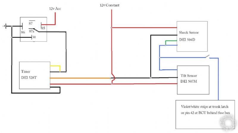
Ok, basically I bought two DEI 504D Shock sensors (One near front of vehicle, one near back of vehicle), one DEI 507M tilt sensor. one DEI 528t pulse timer relay, I bought wire and a 5 pin relay at the automotive store, shrink wrap etc.
I used the diagram attached, however the pin I used is the trunk pin at the BCM plug. So basically
I lengethened the power wires (red) to meet at a (12v constant) power wire at the BCM, both shock sensors and tilt sensor had their own wire however I tied them together at the front shock sensors power wire, and attached and soldered a seperate single wire to lengthen to the BCM power wire. The only I forgot to do was add a fuse. Do I add a fuse for each individual wire or can they share the same wire and fuse? The Tilt relay came with its own 1 amp fuse.
All three sensors (black) grounds are soldered to the timer relays orange wire.
All (blue) trigger wires from the 3 sensors were soldered to it is own extension wire to the trunk pin wire at the bcm.
86 and 30 on the relay and also the Pulse timers black ground wire were soldered together with an extension wire to a GOOD working ground on the chassis near the radio.
The black and white wire of the pulse timer and its yellow wire are connected to the 87a of the relay.
Then the 85 pin of the relay goes to 12v Accessory wire at BCM.
Is this relay hooked up right? Is this whole diagram right? Also did I mess up by wiring all sensors together such as soldering them together into the same power extension wire?
Thank you for looking!
Replies:
Posted By: akurei
Date Posted: May 30, 2015 at 10:37 PM
Forgot to mention, this is on a Nissan 370z
Posted By: howie ll
Date Posted: May 31, 2015 at 12:41 AM
Look in the archives for previous posts on this topic.
There was nothing wrong in theory with your idea it's just that modern factory alarms just don't seem to be compatible with add on accessories.
-------------
Amateurs assume, don't test and have problems; pros test first. I am not a free install service.
Read the installation manual, do a search here or online for your vehicle wiring before posting.
Posted By: akurei
Date Posted: May 31, 2015 at 12:55 AM
I followed dorections of other 370z users who have done it years ago using the same pins and it worked for them. However, I am not able to contact them as it was 4-6 years ago.
So the factory alarm on the 370z is compatible with aftermarket sensors
Posted By: howie ll
Date Posted: May 31, 2015 at 1:02 AM
Unfortunately the manufacturers do software changes every 3 years on average.
The sensor ranges to trigger the factory alarm are different to the signals generated by aftermarket units.
Same factory,right hand drive, I've done a UK spec.370Z where wiring colours and location bore no relation to the equivalent US market vehicle, even engine management terminal configuration was completely different.
-------------
Amateurs assume, don't test and have problems; pros test first. I am not a free install service.
Read the installation manual, do a search here or online for your vehicle wiring before posting.
Posted By: akurei
Date Posted: May 31, 2015 at 1:19 AM
Only a dww things changed with Us spec, but none of them have no affiliation with the plug in at the BCM. Engine and everyth8ng is the same in all models besides adding leds to the front bumper 13' and on
Posted By: akurei
Date Posted: May 31, 2015 at 1:22 AM
I'm gonna enjoy the rest of my saturday. If anybody else can chine in and help out, that would be glorious.
Posted By: howie ll
Date Posted: May 31, 2015 at 1:31 AM
Have you tried either one sensor at a time or diode separation of the blue trigger wires?
-------------
Amateurs assume, don't test and have problems; pros test first. I am not a free install service.
Read the installation manual, do a search here or online for your vehicle wiring before posting.
Posted By: davep.
Date Posted: May 31, 2015 at 1:49 PM
I've never done an add-on like you're attempting, but if the trunk input is contact-closure, it should be possible. Plus other 370 Owners have done it. My guess is that the 528 trigger is grounding through the 507 and shock sensors prior to the sensors becoming active. But that's only a guess. Here's some ideas:
Connect the yellow wire on the 528 directly to ground. Use your relay to only trigger the blk/wht upon key-off.
You will have to add a second relay to interrupt the Ground When Armed (orange on the 507, black on the shock sensors) when IGN = ON.
I would take the 507 and try to get it to trigger the trunk input on its own. Hook it up temporarily to +12 and the trunk trigger. Sit in the car (or run the wires outside if you have to be outside to arm the car), arm the car, ground the orange 507 wire, wait 20-30 seconds for the 507 to become active, and "tilt it". If you can make it work like this, you know it is possible.
I'm not knowledgeable with the shock sensors' output. I'm under the impression some of them are not contact-closure compatible. Some have a dual-stage output, the first being "warn away". Again, testing one on its own would prove that it will work or not.
Please come back, and tell us what you found / did. This is how we learn. Including trying to help by coming up with "this is how I would go about this if it were my project...".
Cheers
Posted By: akurei
Date Posted: May 31, 2015 at 2:13 PM
Shovk sensors only have a power wire, ground, and trigger wire. Shock sensors send a negative pulse to the factory alarms trigger whenever it senses vibration, however, i noticed some people from other makes and models cut the hood trigger plug wire at the hood while wiring up the shock sensor to a relay then attaching to the hood trigger wire by two different wires to complete the circuit. So basically the hood trigger goes through the shock sensor circuit before coming back to its original plug. I have no clue how that works.
However, nissan maximas and 350 and 370zs they just attach the trigger wire to the trigger wire without cutting the factory alarms trigger wire completely.
Is it safe to hook up the shovk sensor straight into the pwr, gnd and trigger wires without a relay and fuse?
Posted By: davep.
Date Posted: May 31, 2015 at 4:03 PM
akurei wrote:
Shovk sensors only have a power wire, ground, and trigger wire. Shock sensors send a negative pulse to the factory alarms trigger
Some do, and some aren't that simple. I know the DEI sensors with a blue and green output are "multiplexed", and are plugged into dedicated "multiplex inputs" on DEI alarm boxes. I have seen DEI shock sensors with only a blue wire, and they are indeed contact-closure, and can trigger a contact-closure input such as a trunk-pin.
Your sensors have green wires, and may behave differently than you think they do. Test them.
akurei wrote:
Is it safe to hook up the shock sensor straight into the pwr, gnd and trigger wires without a relay and fuse?
For the power, the concern would be the fuse size for the circuit the sensor is connected to. Remember you fuse for the wire size, not the load. So if you connect that little red sensor wire to a 50Amp main feed circuit, the little wire will fry without blowing the fuse. If you connect it to a Hot circuit protected by a 5 or 10 amp fuse, then it will be OK.
For the trigger, I have no idea. I'm not familiar with the particular sensors you have, the 370 itself, nor Asian cars in general. Personally, I'm not knowledgeable enough to make an informed assessment.
Test.
|