04 Town and country Remote start rear defroster?
Printed From: the12volt.com
Forum Name: Car Security and Convenience
Forum Discription: Car Alarms, Keyless Entries, Remote Starters, Immobilizer Bypasses, Sensors, Door Locks, Window Modules, Heated Mirrors, Heated Seats, etc.
URL: https://www.the12volt.com/installbay/forum_posts.asp?tid=140722
Printed Date: May 04, 2024 at 1:38 AM
Topic: 04 Town and country Remote start rear defroster?
Posted By: jcharley
Subject: 04 Town and country Remote start rear defroster?
Date Posted: January 24, 2016 at 9:08 PM
Installing a Remote Start on 04 Chrysler Town and Country. I'm looking for the rear def wire location under the dash. I'm also trying to figure out if it is latched or not.
Thanks
Jeff
Replies:
Posted By: mscguy
Date Posted: January 25, 2016 at 1:03 AM
I'm pretty sure HVAC control is over data on that car, so you would have to go to the wire heading to the heating element, through a relay of course
DB/WHT Most likely in driver kick. Just test for it. Use a heavy duty relay. Fuse 13 in the IPM is 40A for it.
Posted By: jcharley
Date Posted: January 25, 2016 at 6:12 AM
Is this the correct way to wire it. Converting negative to positive. https://www.the12volt.com/relays/page1.asp
Also what size wire should I use?
Posted By: jcharley
Date Posted: January 25, 2016 at 8:47 AM
My other question is could just wire it straight to the switch and just pulse a signal to simulate the button being pressed
Posted By: mscguy
Date Posted: January 25, 2016 at 9:50 AM
86 + 87 +12V Fused @ 40A 12awg should be fine, depending how long your run is. Run this wire from the battery. Put the fuse within 12" of battery
85 remote start defog wire - program latched
30 Defog wire going to window
You can only connect your starter wire to the switch if it is a switched ground wire connected to it, that comes out the back of the HVAC module. This isn't the case in your car.
Posted By: jcharley
Date Posted: January 25, 2016 at 8:01 PM
I need 2 more relays 1 each for my 2 sliding doors can I use the same power wire for the other 2 relays as well as the defrost relay?
Posted By: mscguy
Date Posted: January 25, 2016 at 9:47 PM
Relays to unlock the doors, or are they power sliding, and you want to open them?
Posted By: mscguy
Date Posted: January 25, 2016 at 9:55 PM
nevermind. I think you're talking about opening the power sliding doors.
The sliding doors look to communicated over a data bus to their modules again. Your bypass should be able to take care of all that.
I assume you're just going to use two aux outs from your prestige to the flashlogic, and the flashlogic should take it from there.
I've never used one myself, so I'm just reading the manuals as I'm typing this, but I don't see anything about additional relays.
Posted By: jcharley
Date Posted: January 25, 2016 at 10:02 PM
My R/S is the Prestige 997e with flashlogic FLCAN Bypass. This is a copy from the manual
The light blue/green wire pulses to ground via an independent RF channel from the keychain transmitter.
This is a transistorized, low current output, and should only be used to drive an external relay coil.
WARNING!! Connecting the light blue/green to the high current switched output of trunk release circuits,
and some remote start trigger inputs, will damage the control module.
Connect the light blue/green to terminal 86 of a 30 A automotive relay, and wire the remaining relay con-
tacts to perform the selected function of channel 5.
This is why I assumed it needed a relay. The bypass calls for the sliding doors to be wired from the R/S to the Bypass I'm guessing just to choose the output channel. If this is the case does it only get wired to the bypass or does it also need to tap into the sliding door wiring?
Posted By: mscguy
Date Posted: January 25, 2016 at 10:12 PM
That's true to a point. You have to use a relay to interface an aux out with a high current device.
Your aux out is a small -200 (or so) am wire, and your bypass door connection is also a (-) input. All the high current wires for the doors are between the door modules and the door actuators. assuming your bypass door input wires are of similar size to your aux wires (no reason they shouldn't be), you can connect them directly. No relay needed.
Posted By: jcharley
Date Posted: January 25, 2016 at 10:17 PM
So do I just connect the R/S Auxiliary Channels to the bypass or do I have to also tap into the (-) wireS on the sliding door.
So I guess my quotation is do I wire them
1. R/S---Bypass or
2. R/S---Sliding Door---Bypass.
Thanks again for all of your help
Posted By: mscguy
Date Posted: January 25, 2016 at 10:42 PM
R/S --> Bypass
Posted By: jcharley
Date Posted: January 25, 2016 at 10:45 PM
Thank you so much, I'm taking on my 1st R/S install this weekend. I'm actually doing both of my vehicles so I've been trying to make sure I have all the info I need before starting them. I really do appreciate your time and knowledge.
Thank you again,
Jeff
Posted By: jcharley
Date Posted: January 26, 2016 at 10:22 AM
I didn't realize at 1st but for the power supply to the R/S it should be team from the battery as well. Can I use the same power wire for my defrost relay and the R/S or should I run a separate line for both?
Posted By: mscguy
Date Posted: January 26, 2016 at 10:37 AM
Well, your defroster takes a good chunk of current just for itself, and depending on how you're doing your parking lights connection, I think the safe bet is to do two battery runs. If your battery run is only 10' or so, you can probably get away with a single run of 10awg to the battery, and split it inside the vehicle.
Splitting heavy gauge wire is tough sometimes, so if you can spare it, two runs is probably easier.
Posted By: jcharley
Date Posted: January 26, 2016 at 11:46 AM
Thanks, that's what I'll do.
Posted By: jcharley
Date Posted: January 30, 2016 at 1:18 AM
Well I got the remote start installed today and everything seems to be working except for the pass sliding door. I have my left door on channel 5 and my right on channel 6. My left door works but the right does not. I have even tried it on channel 4 and 7 thinking maybe the channel output was bad bUT none of them work either. The door openS with the factory key fob. I'm just not sure what else to do and I've rechecked the wiring a dozen times I have the correct wire hooked up and I have reprogrammed the remote several times. Any ideas or suggestions would be much appreciated.
Thanks
Jeff
Posted By: geepherder
Date Posted: January 30, 2016 at 6:40 AM
Did you use the same value resistors for both doors? The left side is 1.5 kohm, right side is 2.7 kohm. See here: https://www.the12volt.com/installbay/forum_posts.asp?tid=20489.
-------------
My ex once told me I have a perfect face for radio.
Posted By: jcharley
Date Posted: January 30, 2016 at 7:11 AM
I didn't use any resistors because it is all handled through the bypass unit. Is it possible to use data mode and still hard wire the sliding doors?
Posted By: kreg357
Date Posted: January 30, 2016 at 7:27 AM
How about a quick test. You didn't say if you went D2D or W2W but if you went with W2W between the bypass module and the R/S controller....
Disconnect the hardwire connection between them for the right sliding door. Then briefly apply chassis ground to the FLCAN's PURPLE / Black right sliding door input. Does it open ( or close ) to right sliding door?
------------- Soldering is fun!
Posted By: jcharley
Date Posted: January 30, 2016 at 8:06 AM
Yes it did open
Posted By: jcharley
Date Posted: January 30, 2016 at 8:45 AM
I'm not sure what else to test. I've checked the R/S worrying harness for continuity and the wire is good.
Posted By: kreg357
Date Posted: January 30, 2016 at 9:03 AM
The bypass module is doing its' job. It's not getting the signal from the R/S to open the right sliding door. I'm not familiar with the R/S unit you are using but perhaps there is a special sequence you must follow to get that Channel to output?
-------------
Soldering is fun!
Posted By: jcharley
Date Posted: January 30, 2016 at 9:12 AM
Yeah I've tried several times to reprogram the remote. Maybe I'm doing something wrong. I'll keep messing with the remote. How do I test the output on the R/S to see if it's putting out the 300ma?
Posted By: jcharley
Date Posted: January 30, 2016 at 9:14 AM
Yeah I've tried several times to reprogram the remote. Maybe I'm doing something wrong. I'll keep messing with the remote. How do I test the output on the R/S to see if it's putting out the 300ma?
Posted By: jcharley
Date Posted: January 30, 2016 at 9:15 AM
Yeah I've tried several times to reprogram the remote. Maybe I'm doing something wrong. I'll keep messing with the remote. How do I test the output on the R/S to see if it's putting out the 300ma?
Posted By: kreg357
Date Posted: January 30, 2016 at 9:34 AM
Use a Digital Multi Meter set to 20V DC. Connect the Red test lead to +12V constant. Connect the Black test lead to the R/S Channel output wire. The DMM will briefly ( 0.8 sec ? ) show +12V when the output is present.
-------------
Soldering is fun!
Posted By: jcharley
Date Posted: January 30, 2016 at 11:02 AM
Hey thanks for the help, I was able to reset the remote and program it from a blank state and all works now, just gotta find that defrost wire. And if you don't mind how do I test to make sure the defrost wire is correct before I hook into it?
Thanks
Posted By: kreg357
Date Posted: January 30, 2016 at 11:11 AM
I can't find any specific info on the Rear Defrost wire. MSCGUY's info on it is probably accurate. You would be
looking for a 12 to 14 gauge wire in the DKP area in the harness that goes into the door sill and continues to the
rear of the minivan. I this case you are looking for a +12V presence on that wire when the Rear Defroster is ON.
DMM setup is 20V DC. Black test lead to chassis ground. Red test lead to suspect wire. The DMM will read
+12V when the Defroster is ON and 0V when OFF. Toggle it a few time to verify.
This is a high current circuit so a fused 30/40 Amp SPDT relay is required. ------------- Soldering is fun!
Posted By: mscguy
Date Posted: January 30, 2016 at 12:51 PM
Whatever wire I said earlier is what alldata shows. It only does rear window though. Not mirrors.
Kreg did a pictorial on a caravan and it will be a similar wire.
Posted By: davep.
Date Posted: January 30, 2016 at 4:39 PM
Ok. I looked at a wiring diagram for the 04 Town and Country.
The control wire is a wht/pur from the back of the A/C controls, also available at pin 3 of connector C7 on the fuse / relay center. I don't know what pulse is on this wire. The solid state controls are in the "Power Module".
The defog grid wire is dk blu/wht. If you feed this wire directly, it will back-feed into the fuse center and over to the mirrors. So the mirrors will be powered as well. The indicator light will not be lit by powering the dk blu/wht.
Posted By: davep.
Date Posted: January 30, 2016 at 4:42 PM
sorry for the duplicate
On second look, the wht/pur wire I describe as "control" probably IS data. So disregard.
Posted By: kreg357
Date Posted: January 30, 2016 at 6:15 PM
This is a photo from a 2010 Grand Caravan. Your 2004 Town and Country is a earlier model but there seems to be some similarities.
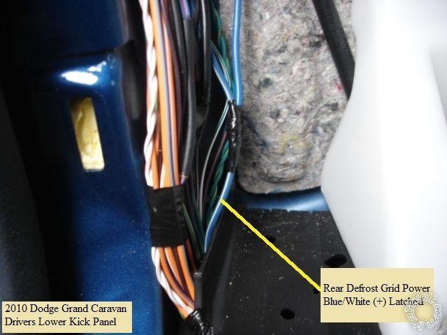
------------- Soldering is fun!
Posted By: jcharley
Date Posted: January 30, 2016 at 8:34 PM
Thank you so
|