Keyless entry, 1993 Ford Explorer
Printed From: the12volt.com
Forum Name: Car Security and Convenience
Forum Discription: Car Alarms, Keyless Entries, Remote Starters, Immobilizer Bypasses, Sensors, Door Locks, Window Modules, Heated Mirrors, Heated Seats, etc.
URL: https://www.the12volt.com/installbay/forum_posts.asp?tid=140970
Printed Date: May 02, 2024 at 11:05 AM
Topic: Keyless entry, 1993 Ford Explorer
Posted By: rheinrich76
Subject: Keyless entry, 1993 Ford Explorer
Date Posted: March 06, 2016 at 2:07 AM
I bought a docooler keyless entry system from Amazon and am having serious difficulty understand their included instructions. I have a 1993 Ford Explorer with power locks. The positive reviews say how easy set up is but I'm having serious trouble even getting starting. If somebody could help me with an eli5 explanation that would be great. Thank you!
Replies:
Posted By: smokeman1
Date Posted: March 06, 2016 at 7:08 AM
First you need to determine whether your Explorer has type B locks or type C locks.
https://www.bulldogsecurity.com/bdnew/vehiclewiringdiagrams.aspx
See the note at the bottom of the above link.
You should use a DMM to test and verify the lock and unlock wires in the drivers kick panel.
Can you post a photo of the wiring diagram for the keyless entry system.
-------------
When all else fails, Read the Instructions
Support the12volt.com Make a Donation
Posted By: rheinrich76
Date Posted: March 06, 2016 at 12:18 PM

This is what I got from Docooler. Please help!
Posted By: smokeman1
Date Posted: March 06, 2016 at 4:32 PM
1.Vehicles with KEYLESS ENTRY are TYPE B, Vehicles without KEYLESS ENTRY are TYPE C.
2. Vehicles with the KEY PAD on the Door are considered to have KEYLESS ENTRY
Which of the above best describe your Explorer? Does your Explorer have a KEY PAD on the drivers door?
-------------
When all else fails, Read the Instructions
Support the12volt.com Make a Donation
Posted By: rheinrich76
Date Posted: March 06, 2016 at 5:13 PM
I would say type C. There are no keypads on the doors and when I bought the car second hand they said nothing about keyless entry.
Posted By: smokeman1
Date Posted: March 06, 2016 at 9:34 PM
Use the link to the download section for Door locks Systems or Door locks DF 1041. In it is an explanation of Type C door Locks. You will probably need a M451 Relay or two SPDT Relays.
I've only done one Type C door lock connection and it was about 4 years ago.
It is a bit tricky, so you will have to fine the wires in the drivers kick panel for testing.
Not sure which example on your wiring sheet would be Type C.
Maybe another forum member could chime in.
-------------
When all else fails, Read the Instructions
Support the12volt.com Make a Donation
Posted By: rheinrich76
Date Posted: March 06, 2016 at 9:39 PM
I don't see a link to the download section. I'm still very new to this website. Are you talking about the main menu on top of the webpage? I'll look for it. I was hoping when you said C you were referencing the C underneath fig 3 negative trigger. Yes, I hope I can get all the help I can. I assume I can find these inexpensive? relays at radio shack? My mechanic said he could do it but he was quoting me a possible three hour job @ $90 per hour. I was hoping it was just cut these wires, connect them to the wires on my module and away I go. Will I need a degree in electrical engineering to do this?
Posted By: rheinrich76
Date Posted: March 06, 2016 at 9:41 PM
Let me clarify, if need be, that it is a remote keyless entry system from Docooler I bought off of amazon for $15.
Posted By: smokeman1
Date Posted: March 06, 2016 at 9:51 PM
https://www.the12volt.com/installbay/downloads.asp?srch=all&term=1041
No need to clarify, I understand what you have, I'm just not real familiar with the Type C locking system your Explorer has.
If I was taking a GUESS, I would say "D" on your diagram. But you need to test and verify
-------------
When all else fails, Read the Instructions
Support the12volt.com Make a Donation
Posted By: kreg357
Date Posted: March 07, 2016 at 7:55 AM
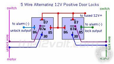
Looks like the unit has built in door lock relays. No need for a 451M module. Here is the wiring if you have Type C door
locks :
Basically the Orange, White and Yellow wires are for lock. The Yellow wire is Pin 87. The White wire is Pin 30 and the
Orange wire is Pin 87a. So for the lock circuit in a Type C vehicle its' :
Yellow to +12V constant through 15 Amp fuse
White to the Motor side of the vehicles Lock wire
Orange to the Switch side of the vehicles Lock wire
The Explorers Lock wire is Pink / YELLOW and found in the DKP.
For the unlock circuit, you will use the same setup with the three wires with the Black tracer as follows :
Yellow/Black to +12V constant (joined with the Yellow wire)
WHITE/ Black to the Motor side of the vehicles Unlock wire
ORANGE / Black to the Switch side of the vehicles Unlock wire
The Explorers Unlock wire is Pink/Light Green and found in the DKP.
In the diagram below, the Red wire is the units Yellow & Yellow/Black wires. The Purple wires are the Orange & ORANGE / Black
wires. The Dark Blue wires are the White and WHITE/ Black wires. The Light Blue and Green wires are internal ( as are the relays ).
You definitely want to test these vehicle lock wires to ensure that it is Type C. The easy way is to find the correct pair of
wires and use a Digital Multi Meter as follows : DMM set to 20V DC. Red test lead to suspect wire. Black test lead to
solid frame ground. DMM should read 0V. Press and hold the door lock ( or unlock ) button, DMM should read +12V.
Additional in can be found in the DEI Tech Tip 1041 Mr. Smoke mentioned. ------------- Soldering is fun!
Posted By: rheinrich76
Date Posted: March 07, 2016 at 12:11 PM
Thank you all very much. Now all I need to do is buy a digital multimeter and start testing. I work the next couple days so I'll report back when I can. Again, thank you very much for your help!
Posted By: rheinrich76
Date Posted: April 12, 2016 at 1:43 PM
Okay, finally got a DMM. I tested the below wires found in my kick panel and here are the results. Do I need to test any other wires? Do you need a pictures of the cluster of wires? What's my next step?
Thank you!
Yellow activates 0.18
Orange is 12 by itself
No white
Only white with green line, white with yellow line.
Pink with yellow line activates 10 on lock press
Yellow with black line 0.20 activates when pressed.
Posted By: rheinrich76
Date Posted: April 18, 2016 at 3:24 PM
Are you guys still there?
Posted By: kreg357
Date Posted: April 18, 2016 at 8:18 PM
Sorry, missed your update post.
I haven't done a 1993 Explorer in many years. Wasn't taking photos back then either. Here is the only info I can find :
ReadyRemote :
Power Lock pink / YELLOW 5wi driver kick, door harness
Power Unlock pink/green 5wi driver kick, door harness
Bulldog Security :
POWER LOCK PINK / YELLOW (TYPE C) IN DRIVERS KICK PANEL
POWER UNLOCK PINK/LIGHT GREEN (TYPE C) IN DRIVERS KICK PANEL
While it is very possible the wire colors have faded with age, you should try to locate two similar gauge wires in DKP
area that are going out to the door. We are assuming that the locks are the factory system and not an add-on system.
Anyway, the Pink / YELLOW wire you found seems to test correctly as a Type C Lock wire. Continue searching in that same
harness for the Pink/Light Green Unlock wire.
Once you have the correct wires, cut them at a convenient accessible location. Verify the the door lock control buttons no
longer work. Use the info in the DEI TechTip 1041 to determine which end of the cut wire is the motor and which is the
switch, then wire it up as per the previously mentioned wiring for your new system. When you are done the door lock
buttons should work and the new system remotes should work also. ------------- Soldering is fun!
Posted By: rheinrich76
Date Posted: April 18, 2016 at 8:52 PM
Ok I think I got it. Which of the letters A-E on the diagram that came with my RKE Module do I go by? Which of its wires gets connected to the cars pink wires? "Central locking" has 6 wires available on my module. It seems I only need 4. 2 for each pink wire. Which four?
Posted By: kreg357
Date Posted: April 18, 2016 at 9:37 PM
Basically the Orange, White and Yellow wires are for lock. The Yellow wire is Pin 87. The White wire is Pin 30 and the
Orange wire is Pin 87a. So for the lock circuit in a Type C vehicle its' :
Yellow to +12V constant through 15 Amp fuse
White to the Motor side of the vehicles Lock wire
Orange to the Switch side of the vehicles Lock wire
The Explorers Lock wire is Pink / YELLOW and found in the DKP.
For the unlock circuit, you will use the same setup with the three wires with the Black tracer as follows :
Yellow/Black to +12V constant (joined with the Yellow wire)
WHITE/ Black to the Motor side of the vehicles Unlock wire
ORANGE / Black to the Switch side of the vehicles Unlock wire
The Explorers Unlock wire is Pink/Light Green and found in the DKP. ------------- Soldering is fun!
Posted By: rheinrich76
Date Posted: April 26, 2016 at 9:57 PM
Page 6: Type C: Reverse Polarity of DEI TechTip 1041 only mentions locating the master switch. Am I looking at the right one? I need to know, when I cut the wire, which of the two ends goes to the switch and which end goes to the motor right?
Posted By: rheinrich76
Date Posted: April 26, 2016 at 10:32 PM
Ok I have identified the lock and unlock wires and wired how you said. Which of the vehicles wires do the two yellow wires get connected to? What about the RKE's red wire? Obviously the black wire on the RKE goes to a grounded point on the chassis. I also have two reds..one with the black line.
Posted By: davep.
Date Posted: April 27, 2016 at 8:47 AM
BLACK/ white in the same harness you found the lock wires is power for the locks. Tap this wire and attach yellow and yellow/black. You can also attach the RKE red wire to the same place. It will all be protected by the Explorer's Power Lock circuit breaker.
Posted By: rheinrich76
Date Posted: April 27, 2016 at 11:03 AM
Thanks to everyone who helped me and I appreciate your patience. I made the last connections this morning and it works. Eventually I'd like to get the lights to flash but for now I'm happy. When I do, I know where to go though.
|