Clifford 5706 wiring.
Printed From: the12volt.com
Forum Name: Car Security and Convenience
Forum Discription: Car Alarms, Keyless Entries, Remote Starters, Immobilizer Bypasses, Sensors, Door Locks, Window Modules, Heated Mirrors, Heated Seats, etc.
URL: https://www.the12volt.com/installbay/forum_posts.asp?tid=141206
Printed Date: May 02, 2024 at 5:03 AM
Topic: Clifford 5706 wiring.
Posted By: d4enx
Subject: Clifford 5706 wiring.
Date Posted: April 26, 2016 at 11:36 AM
Hello everyone, I've read a few of these posts and it seems you get a whole load of questions regarding these types of alarm so I'll try not to take up much of you time.
I have the Clifford 5706 2 way, similar if not the same as the viper 5706.
I have a MK1 Ford Focus RS.
I've done allot of wiring in the past and am quite confident that I can wire it in but there a few things that are confusing me.
Most of the wires state (-) 200ma, now does this mean that they will pulse to ground to activate which ever circuit/relay?
If so what if the desired circuit (e.g. Door locks) require a 12v pulse as I'm sure some of them do.
Some of the descriptions for the wires I need to tap into are a little confusing, apologies if some of these are obvious but I'm not that familiar with some of the terminology.
For e.g.
What is the,
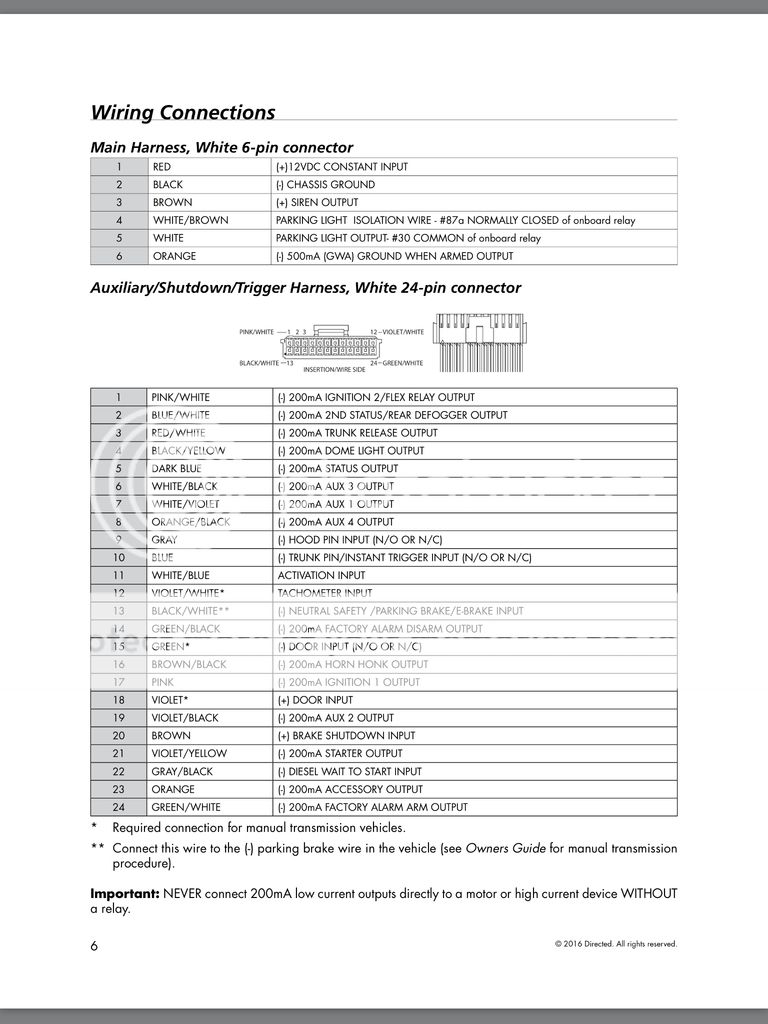
-Main Harness-
- (-) 500ma (GWA) Ground when armed output.
-Auxiliary/shutdown/trigger harness-
- (-) ignition 2 flex relay output.
- (-) 200ma status output.
- Activation input
And last question.
- (-) Door input (N/O or N/C)
- (+) Door input.
There's these 2 wires for door input, do they both need to be used or is either the negative or positive one used depending on my cars wiring.
Any help would be greatly appreciated.
Regards,
Dean.
Replies:
Posted By: howie ll
Date Posted: April 27, 2016 at 4:54 PM
1) They are both the same.
2) Trunk (hatch release), BLACK / YELLOW at the switch or GEM module.
This is a low current NEG wire so your RED / white, 3 on the 24 pin harness can be directly connected.
The only case for a relay would be for headlight activation.
N.B BROWN / black at 16 can also connect directly, should be blue/black,loom from steering column.
There's also a way if your vehicle has OEM deadlock to deadlock the vehicle on arm and normal lock on ignition using a relay and an aux.
3) The GWA no 6 could drive either an extra relay for ignition cut (not advisable, too dangerous, a bad connection could stall the engine at speed) or extra LED's.
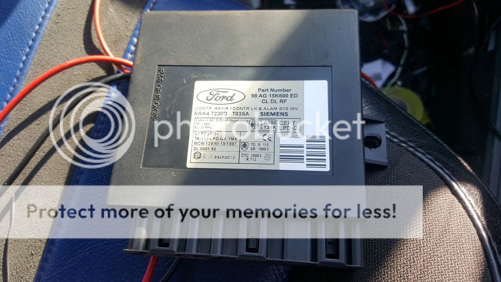
4) You will need to bypass your OEM immobiliser using a DEI 556U, since I assume you're using this for it's intended purp[ose as an alarm + remote start. the dark blue status output triggers it. You will need an extra plain key, Timpsons etc. Must be chipped.
5) NO door triggers, go to the interior and hatch lights, these will be on plugs at your GEM module, that's the box above your throttle pedal. 2 or 4 doors contacts are all separate, need to be dioded together and back feed dioded see here, Ford 1076 diagram VERY important otherwise your alarm will trigger off every half hour or so.
6) Ignore (+) door trigger N/A.
7) Indicators are at GEM module, blue and blue/red you will need to Y-diode out the white wire (set (+)) with two X 1N5404 diodes.
A very easy install (when you've done loads) every thing bar the siren and bonnet switch is right hand under dash.
Just a word, if you have to ask these questions, get a pro to install it.
-------------
Amateurs assume, don't test and have problems; pros test first. I am not a free install service.
Read the installation manual, do a search here or online for your vehicle wiring before posting.
Posted By: d4enx
Date Posted: April 28, 2016 at 12:24 AM
thanks mate i appriciate your reply, once i understand it ill be fine with the fitting, ive done allot of wiring and am confident i could make a good job of it but ive never worked to a wiring diagram like this before and neded some help with the wire descriptions.
standard security etc.. isnt a problem as i dont have a standard ecu and the fors PATS system isnt active.
and what do you mean when you said "there both the same"
and being honest if i knew of a mobile auto eectrician that could do it and wouldnt cost the earth if probobly pay them to do it to save me the hassle. but i dont know of anyone in my area and would rather get someone that had been recomended.
Posted By: howie ll
Date Posted: April 28, 2016 at 1:17 AM
Where are you?
Viper = Clifford, Same product.
-------------
Amateurs assume, don't test and have problems; pros test first. I am not a free install service.
Read the installation manual, do a search here or online for your vehicle wiring before posting.
Posted By: d4enx
Date Posted: April 28, 2016 at 1:50 AM
im in nottingham uk. the one thing thats confusing me the most is the (-) and (+) symbols. does that mean e out put on that wire will either be (-) pulse to ground and (+) pulses 12v?
Posted By: howie ll
Date Posted: April 28, 2016 at 1:56 AM
Yes.
-------------
Amateurs assume, don't test and have problems; pros test first. I am not a free install service.
Read the installation manual, do a search here or online for your vehicle wiring before posting.
Posted By: d4enx
Date Posted: May 04, 2016 at 5:26 AM
Hey everyone,
So I'm going to attempt to install this alarm, I've gone through the wires and this is my take on it all. Can anyone tell me if this looks correct? Take into account that I do not have a factory alarm.
Main harness.
1-12v live
2-ground/earth
3-solid red silent wire (other silent wire to earth)
4-87a pin on the indicators/turn signal relay
5-30 pin on the indicators/turn signal relay
6-not used.
24 pin connector
1-not used
2-not used
3-tailgate switch - pulse.
4-interior light negative wire.
5-not used
6-not used
7-not used
8-not used
9-bonnet pin
10-tailgate interior light negative,
11- s this needed?[/B
12-rpm input. ]what wire would i use without standard ecu?
13-handbrake switch, ground when on.
14-not used
15-interior light negative, for door open indication?
16-not needed
17-not needed
18-not needed
19-not needed
20-brake or clutch switch, positive
21-not needed
22-not needed
23-not needed
24-not needed
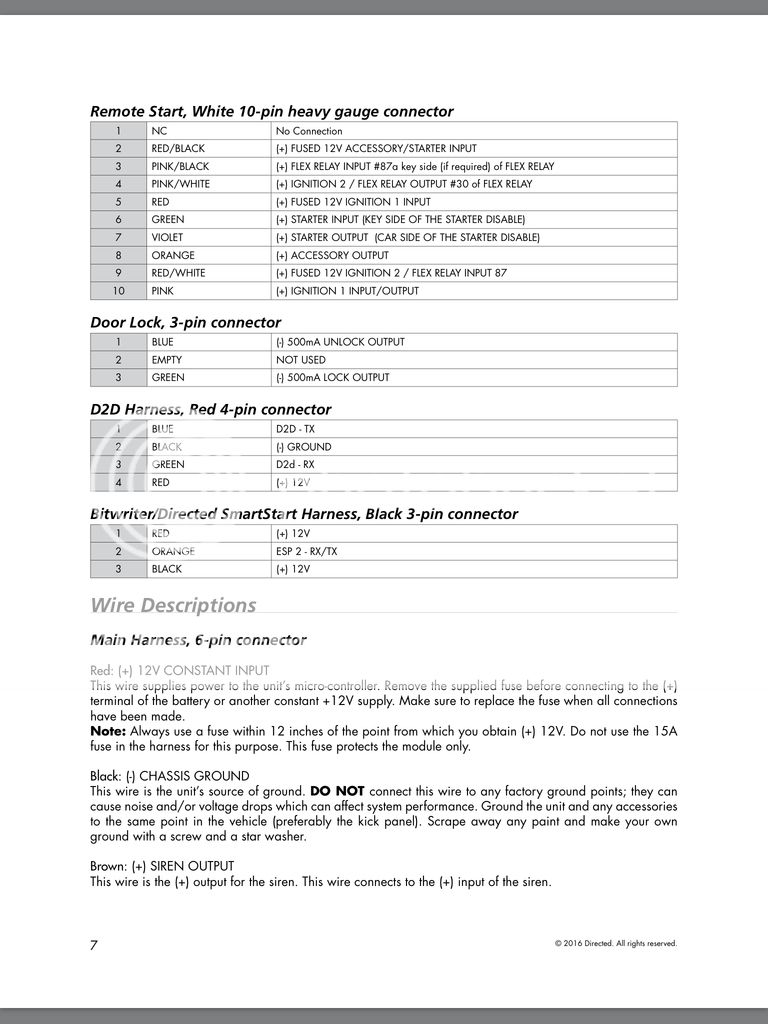
Remote start heavy gauge plug.
1-nothing
2-12v live
3-not needed
4-ignition 2 ](is this 12v when ignition is on wire from key barrel?)
5-12v live
6-starter motor key side
7-starter motor, motor side (started motor wire from the key barrel cut and these wires to go to one of each ends?)
8-12v accessory output. (The wire that gets 12v but not when cranking)
9-12v live
10-12v ignition live
If I'm wrong please do correct me.
Regards,
Dean
Posted By: d4enx
Date Posted: May 04, 2016 at 5:35 AM
I will also be joining at the gem module where possible as advised and have order some of the diodes, I'm familiar with what diodes do but some more information on the exact wiring of these would be greatly appreciated
Posted By: howie ll
Date Posted: May 04, 2016 at 11:50 AM
2 X 1N5404 diodes for the indicators, Y-branch out from the white as mentioned in my first post No 7.
Silent red? Try siren brown, goes to siren red and black wire on siren to ground.
24 pin connector.
3 RED / brown direct to BLACK / YELLOW at hatch release switch.
11 No.
12 Tach injectors, 4 are the same colour use any of the other 4.
15 Yes and again look up Ford 1076 here.
20 to brake output, i.e. your stop lamp bulb side.
-------------
Amateurs assume, don't test and have problems; pros test first. I am not a free install service.
Read the installation manual, do a search here or online for your vehicle wiring before posting.
Posted By: d4enx
Date Posted: May 04, 2016 at 1:41 PM
Thanks howie, I really appreciate your help, And for editing the bolt lettering out of the post.
I'll look up that wiring right now.
And the injector wires for the tach? I'm assuming this is because it gives a constant and accurate pulse with every rotation of the engine? But aren't they all 12v live and get a pulse to ground to activate?
Regards,
Dean.
Posted By: howie ll
Date Posted: May 04, 2016 at 1:45 PM
Doesn't matter though I think you're technically wrong it's a 12V+ ign minus the 1.5-3 V+ of the pulsing wire and the unit looks for that pulsing to seer tach you can measure it with a meter set to 20VAC, you'll get 1.5-5 V+ at idle on AC setting on your digital multi-meter.
-------------
Amateurs assume, don't test and have problems; pros test first. I am not a free install service.
Read the installation manual, do a search here or online for your vehicle wiring before posting.
Posted By: d4enx
Date Posted: May 07, 2016 at 3:29 AM
ok so i think im as clued up as im going to get, looking at these wiring diagrams for the interior light and i right in thinking that if going to the interior light the door latch wires from the alarm go to the black and blue wire (pin 3) on the gem module and that i must follow the ford 1076 wiring diagram to diode them in a Y, so both wires each with a diode to that one wire?
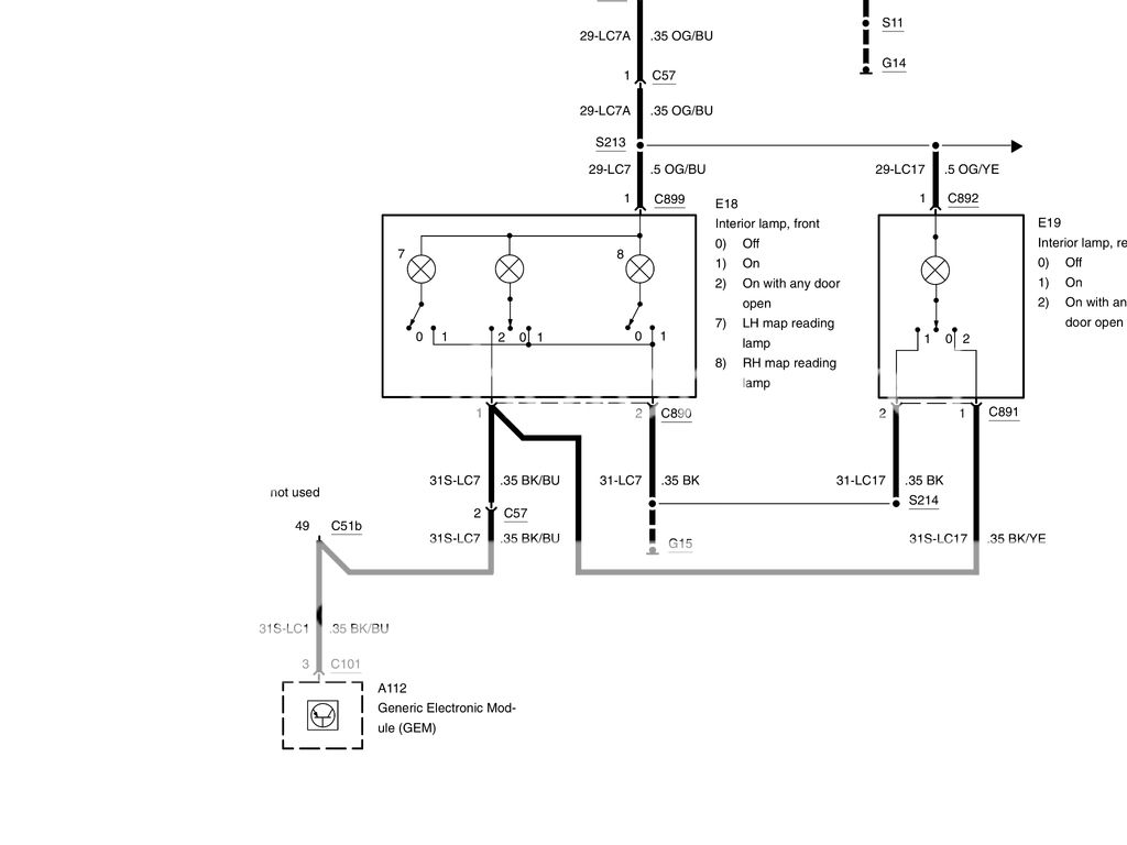
failing that there is the door latch wires them selfs seen in this diagram.
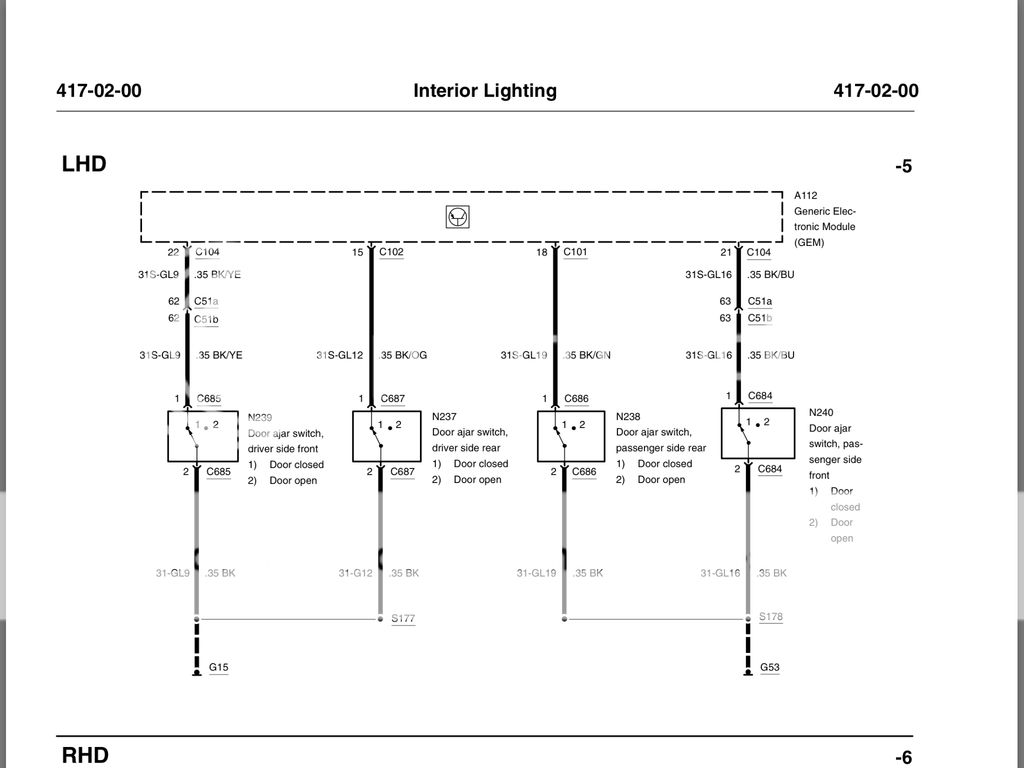
and then will do the same for the tailgate wire.
Posted By: howie ll
Date Posted: May 07, 2016 at 3:59 AM
Yes, 4 diodes plus one at hatch.
Pins 21 and 22. Hatch should be BLACK/ blue always picked up that one in loom at passenger side floor.
-------------
Amateurs assume, don't test and have problems; pros test first. I am not a free install service.
Read the installation manual, do a search here or online for your vehicle wiring before posting.
Posted By: d4enx
Date Posted: May 07, 2016 at 5:25 AM
perfect, thanks for your help mate ill let you know how i get on.
Posted By: d4enx
Date Posted: May 13, 2016 at 1:30 AM
ok so im going to make a start on wiring this alarm in today, again these are some really simple questions i have but i want to make sure i understand it 100% as i dont want to have to start undoing what im going to do.
what i believe to be the module i need to tap into for most of the smaller gauge wires has 2 plugs on it as i have a 2 door, but there numbered 1-16 on each. some of the wiring diagrams requir pins e.g. pins 21 and 22, am i missing something onbvious or am i looking in the wrong place?
also am i able to test each wire by sending it to ground to ensure it does what i want it to?.
and would the high gauge accesory wire be used? im asuming this it one from the ignition barrel that is 12v when ignition is on but not when cranking?
also i had an old toad alarm fitted which ive now removed and some of the wires going to the gem module and the drives door loom bridge across each other, is this normal or so i remove these?
thanks.
Posted By: howie ll
Date Posted: May 13, 2016 at 3:13 PM
You're making a simple job over complicated.
Throw away the DMM and use a Snap-On test light with an incandescent bulb.
Then just test the door lock triggers are at plugs on end of the module, door open at the other end. Indicators blue and blue red are in the middle.
-------------
Amateurs assume, don't test and have problems; pros test first. I am not a free install service.
Read the installation manual, do a search here or online for your vehicle wiring before posting.
Posted By: howie ll
Date Posted: May 13, 2016 at 3:16 PM
Use the orange high current ACC wire, remove the Toad wires then check everything functions before proceeding.
-------------
Amateurs assume, don't test and have problems; pros test first. I am not a free install service.
Read the installation manual, do a search here or online for your vehicle wiring before posting.
Posted By: d4enx
Date Posted: May 13, 2016 at 5:17 PM
I more than likely am however I've got most of the wires wired in and am going to finish the rest tomorrow, after asking about the gem module on another forum I've had multiple people tell me that these plugs and the box is not the GEM module and that the early focus's (which mine is) hasn't got a GEM module, well that's thrown me completly. Basically all I have left to do that I'm unsure of is the door lock/unlock wires, now I'm in doubt that I have a gem module and most of the wiring diagrams I have seem useless to me now. To be perfectly honest for these 2 wires I don't know where to start.
I've removed the toad alarm and put the wiring that was obviously not standard or that had been cut etc.. back to normal and everything working as it should again.
Posted By: howie ll
Date Posted: May 13, 2016 at 5:29 PM
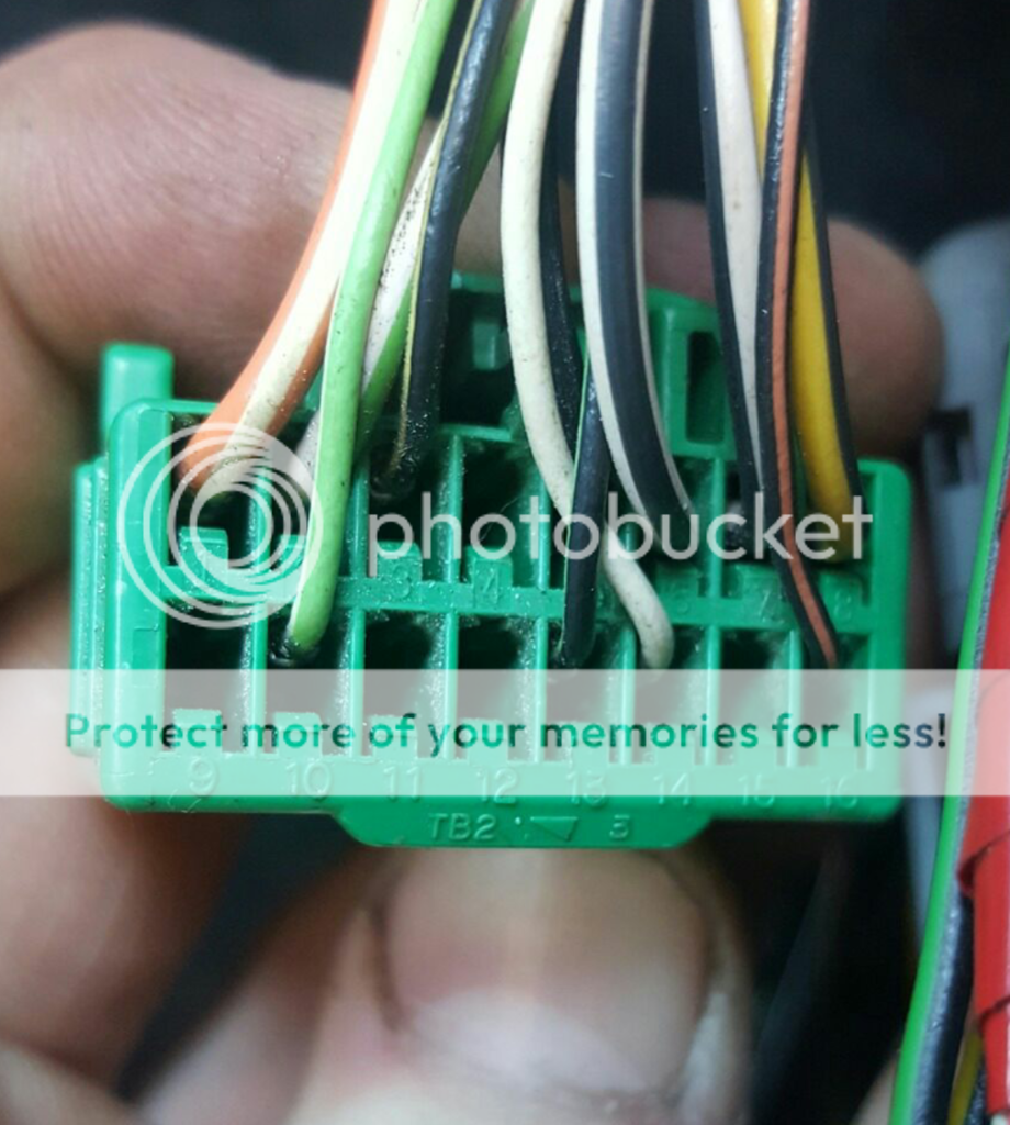
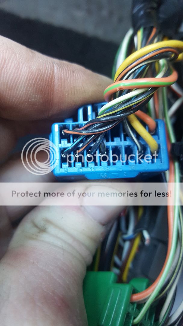
BLACK/ orange lock and BLACK/ green unlock pins 13 and 16 on the green plug TB2/3 see the photos above. Test by grounding each with passenger door shut and driver's door catch thrown over, I believe you will also need to push in the contact switch on the door shut.And yes ALL Focuses had the GEM, installing alarms since 98/9 there was an electrics change in 2000/1 but the GEM was always there.
Plug TB2 Has the driver and passenger door triggers plus possibly low current NEG hatch release and also hatch trigger though I wire the release at the switch and the hatch trigger left front as previously explained.
Come to think of it your GEM plugs don't contain indicator wires (blue and blue/red) they will be at the hazard switch which makes your vehicle the early version wiring pre-2001.
-------------
Amateurs assume, don't test and have problems; pros test first. I am not a free install service.
Read the installation manual, do a search here or online for your vehicle wiring before posting.
Posted By: d4enx
Date Posted: May 17, 2016 at 1:41 PM
Well so far so good I've got everything wired in and working apart from the door open and tailgate open wires. I wanted to go to the interior light but for some reason the light is constantly on even with the doors closed. Will try and figure out the problem but I've found the door ajar switch wires that go to ground when the doors open, but struggling to find the tailgate switch that does the same.
Posted By: howie ll
Date Posted: May 17, 2016 at 1:45 PM
I've already told you about the last and going to the door contacts rather than the dome light will eliminate the dome light problem, NB it only shuts down after closing with the original OEM remote, data driven.
-------------
Amateurs assume, don't test and have problems; pros test first. I am not a free install service.
Read the installation manual, do a search here or online for your vehicle wiring before posting.
Posted By: d4enx
Date Posted: May 19, 2016 at 12:45 PM
Huge thanks for your help howie got it all wires up and everything now works perfectly, haven't had chance to try the remote start though as I'm currently working on the engine but I'm sure it'll be fine.
|


